|
|
|
Porsche, and the Porsche crest are registered trademarks of Dr. Ing. h.c. F. Porsche AG.
This site is not affiliated with Porsche in any way. Its only purpose is to provide an online forum for car enthusiasts. All other trademarks are property of their respective owners. |
|
|

  |

| tach |
 May 29 2015, 05:11 PM May 29 2015, 05:11 PM
Post
#1
|
|
Member  Group: Members Posts: 79 Joined: 6-November 09 From: Minnesota Member No.: 11,016 Region Association: Upper MidWest |
Let me re-word the question please. Where does the 3mm vacuum hose go with the question mark by it in the drawing or does it get plugged?
Second question. What hose hooks to the tiny black plastic line in the engine compartment that goes through the tunnel to the reservoir on top of the gas tank. (No canister in engine compartment). 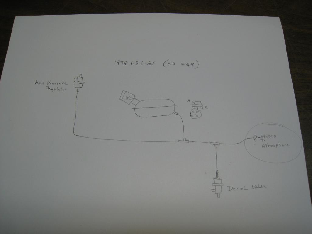 |
   |

 
|
| jcd914 |
May 29 2015, 11:01 PM
Post
#2
|
|
Advanced Member Group: Members Posts: 2,081 Joined: 7-February 08 From: Sacramento, CA Member No.: 8,684 Region Association: Northern California |
No the vacuum hose going to the decel valve and fuel pressure regulator should not go to an open port in the air filter housing. Not only would you be getting dirty air ,you wuld have no vacuum to the decel or fuel press reg.
Pelican Parts has good diagrams on the site: 1.8 Fuel & Vacuum Diagrams Jim |
|
|
|
| Dave_Darling |
May 29 2015, 11:09 PM
Post
#3
|
|
914 Idiot Group: Members Posts: 14,985 Joined: 9-January 03 From: Silicon Valley / Kailua-Kona Member No.: 121 Region Association: Northern California |
There should never be a direct connection from the outside to the manifold. Especially on a 1.8--unmetered air is something you really do not want.
Let's see. The Decel Valve should get hooked to manifold pressure. The fuel rail as well. And the AAR and DV both let air from "in front of" the throttle valve to the manifold, so they each have large-ish connections to the manifold. The distributor dashpot will have hoses going directly to the throttle body--likely only one, as most of the 74s did not have vacuum advance. The single connection on the throttle body would plug into the fitting on the distributor dashpot that points back toward the distributor body, while the other would be left open. The second question: It sounds as if your car has the engine-bay-mounted charcoal canister. The small hose hooks to the small fitting on that, and goes up to the expansion chamber on top of the fuel tank. (Earlier cars had the canister on top of the fuel tank, with the two larger air lines running along the driver's rocker panel.) --DD |
|
|
|
| tach |
May 30 2015, 02:19 PM
Post
#4
|
|
Member Group: Members Posts: 79 Joined: 6-November 09 From: Minnesota Member No.: 11,016 Region Association: Upper MidWest |
I reworded the question because it may have been a bit confusing the way it was written. Thank you. Hope you can help me. No EGR, not a California car.
|
|
|
|
| jcd914 |
May 30 2015, 04:01 PM
Post
#5
|
|
Advanced Member Group: Members Posts: 2,081 Joined: 7-February 08 From: Sacramento, CA Member No.: 8,684 Region Association: Northern California |
This is from the Pelican diagram page I linked to in my first post.
Ignore the EGR valve hoses and the rest should apply. Jim  |
|
|
|
| Old Yella |
May 30 2015, 04:45 PM
Post
#6
|
|
Old Yella Group: Members Posts: 158 Joined: 2-July 13 From: Canberra Australia Member No.: 16,086 Region Association: Southwest Region |
Please EDUMAKATE me.
I have a 2.0 and a slightly different set up but what's the fuel pressure regulator being connected to the decell valve and then the plenum for? The end of the pressure regulator is the adjustment knob. Something looks screwy with the diagram. |
|
|
|
| jcd914 |
May 30 2015, 05:55 PM
Post
#7
|
|
Advanced Member Group: Members Posts: 2,081 Joined: 7-February 08 From: Sacramento, CA Member No.: 8,684 Region Association: Northern California |
QUOTE(Old Yella @ May 30 2015, 03:45 PM)  Please EDUMAKATE me. I have a 2.0 and a slightly different set up but what's the fuel pressure regulator being connected to the decell valve and then the plenum for? The end of the pressure regulator is the adjustment knob. Something looks screwy with the diagram. 2.0L Fuel press reg is different than the 1.8L. 1.8L Fuel press reg uses vacuum change to make a slight pressure change between Idle (no load) and WOT (full load). Jim |
|
|
|
|
1 User(s) are reading this topic (1 Guests and 0 Anonymous Users)
0 Members:

|
Lo-Fi Version | Time is now: 15th May 2024 - 01:36 AM |
Invision Power Board
v9.1.4 © 2024 IPS, Inc.