|
|
|
Porsche, and the Porsche crest are registered trademarks of Dr. Ing. h.c. F. Porsche AG.
This site is not affiliated with Porsche in any way. Its only purpose is to provide an online forum for car enthusiasts. All other trademarks are property of their respective owners. |
|
|


| Spoke |
 Jul 13 2015, 08:57 PM Jul 13 2015, 08:57 PM
Post
#1
|
|
Jerry  Group: Members Posts: 7,185 Joined: 29-October 04 From: Allentown, PA Member No.: 3,031 Region Association: None |
I'm preparing to install a 2056 dual Weber carb engine in my car and was thinking about how to control the fuel pump. I'll use the existing FI fuel pump relay as done many times before by grounding the appropriate pin on the FI ECU connector to energize the relay with ignition on.
I want to add a safety feature to power the fuel pump only when the engine is running. This is done with all FI systems in case of accident so the fuel pump doesn't keep pumping if the engine has stopped. I want the same functionality with carbs. I'm designing a PCB to power the fuel pump like DJET systems do: Turn the key on and the fuel pump charges the system for 2 seconds then turns off. When the engine starts turning, the fuel pump will run. I forsee 4 wires: GND: picked up on a chassis lug near the relay board 12V switched: Picked up on the FI ECU socket Relay: Picket up on the FI ECU socket Coil Neg: This goes to the tach as well. The coil negative would be the signal to indicate engine running. Should I consider any other functionality of the fuel pump controller? Anyone interested in a PCB like this? Does a 2 second precharge do anything for a carbed engine? I could see if the carb bowls were not full but other than that, not sure a precharge does anything. |
   |

 
|
  |
Replies(20 - 36)
| JFJ914 |
Jul 18 2015, 08:33 AM
Post
#21
|
|
Senior Member Group: Benefactors Posts: 813 Joined: 13-June 03 From: Alpharetta, GA Member No.: 814 Region Association: South East States |
QUOTE(Mark Henry @ Jul 18 2015, 08:44 AM)  QUOTE(Valy @ Jul 18 2015, 01:12 AM) And still, my single relay circuit does the same job but its much simpler. (IMG:style_emoticons/default/agree.gif) I can't see why all this work? (IMG:style_emoticons/default/confused24.gif) Is it just to keep the relay on the board? (IMG:style_emoticons/default/wacko.gif) Again why? It's carbed so it's not like it's concours. (IMG:style_emoticons/default/poke.gif) The relay Valy posted works on oil pressure, the the relay I posted uses a simple tach input, both could be quickly stealth installed without a single OEM wire cut...so I don't get it? Sometimes the challenge of reinventing the wheel proves irresistible! |
 |
|
| Spoke |
Jul 18 2015, 09:54 AM
Post
#22
|
|
Jerry Group: Members Posts: 7,185 Joined: 29-October 04 From: Allentown, PA Member No.: 3,031 Region Association: None |
QUOTE(Mark Henry @ Jul 18 2015, 08:44 AM) QUOTE(Valy @ Jul 18 2015, 01:12 AM) And still, my single relay circuit does the same job but its much simpler. (IMG:style_emoticons/default/agree.gif) I can't see why all this work? (IMG:style_emoticons/default/confused24.gif) Keep in mind that I am an engineer and it's the engineers code to solve any problem in a manor such that the problem didn't need to be solved in the first place and to make the solution so complicated that no one can figure it out. (IMG:style_emoticons/default/beerchug.gif) QUOTE Yes the relay is already there and want to provide the bit of protection that shuts the pump off when the engine stops. I want to be able to switch from carbs to FI easily. This circuit will mount in the FI power connector on the relay board with one wire going to chassis and the other to the coil. QUOTE Just having fun with electronics. QUOTE The relay Valy posted works on oil pressure, the the relay I posted uses a simple tach input, both could be quickly stealth installed without a single OEM wire cut...so I don't get it? Again, fun with electronics. Here's a board I just finished for my 3d printer. It is an LED ring that will fit right inside the carrier to illuminate the work. Could have bought a generic LED ring for $30 but this one is more intricate and fits beautifully on the printer. Theirs has 6 LEDs and mine has 8 LEDs so mine is better. Attached thumbnail(s) 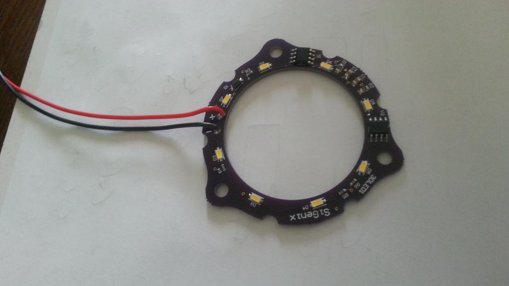
|
|
|
|
| Valy |
Jul 18 2015, 11:06 PM
Post
#23
|
|
Senior Member Group: Members Posts: 1,677 Joined: 6-April 10 From: Sunnyvale, CA Member No.: 11,573 Region Association: Northern California |
You're not true to your signature: "CSOB of PA"
(IMG:style_emoticons/default/smile.gif) |
|
|
|
| euro911 |
Jul 18 2015, 11:24 PM
Post
#24
|
|
Retired & living the dream. God help me if I wake up! Group: Members Posts: 8,911 Joined: 2-December 06 From: So.Cal. & No.AZ (USA) Member No.: 7,300 Region Association: Southern California |
QUOTE(Spoke @ Jul 18 2015, 08:54 AM) ... Keep in mind that I am an engineer and it's the engineers code to solve any problem in a manor such that the problem didn't need to be solved in the first place and to make the solution so complicated that no one can figure it out. (IMG:style_emoticons/default/beerchug.gif) (IMG:style_emoticons/default/laugh.gif) I remember designing similar elaborate circuitry, but then I had to write documentation so our field engineers had a road map for troubleshooting. Then I had to write additional documentation allowing normal folks to operate the device(s). Glad I'm retired now (IMG:style_emoticons/default/aktion035.gif) |
|
|
|
| Spoke |
Jul 19 2015, 08:57 AM
Post
#25
|
|
Jerry Group: Members Posts: 7,185 Joined: 29-October 04 From: Allentown, PA Member No.: 3,031 Region Association: None |
Here's a first cut at the PCB and the FI plug. I can shrink the board a bit. Right now the entire assembly is a bit over 2 inches tall.
Attached image(s) 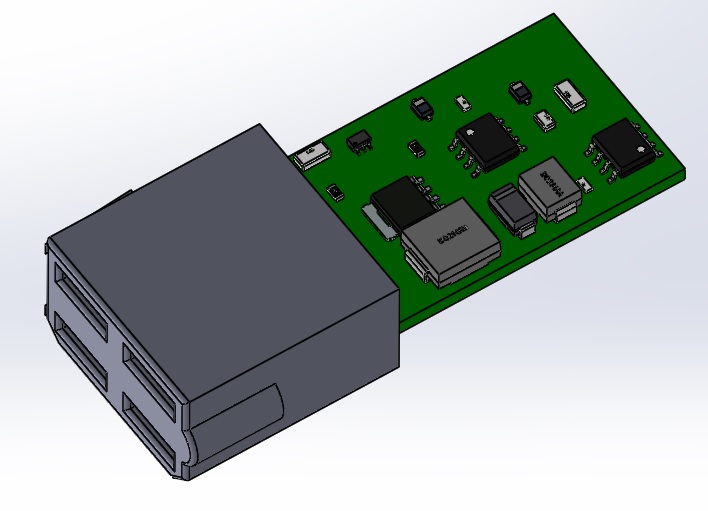
|
|
|
|
| Spoke |
Jul 19 2015, 04:17 PM
Post
#26
|
|
Jerry Group: Members Posts: 7,185 Joined: 29-October 04 From: Allentown, PA Member No.: 3,031 Region Association: None |
Here's a simpler circuit which interfaces to the oil pressure switch to sense engine running. I think I'll add an LED to indicate the pump is powered.
Attached thumbnail(s) 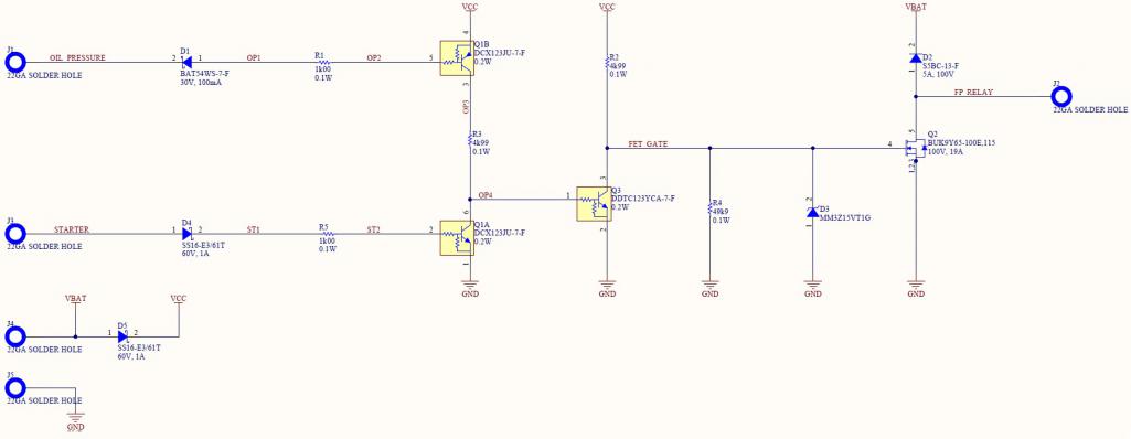
|
|
|
|
| Spoke |
Jul 19 2015, 09:51 PM
Post
#27
|
|
Jerry Group: Members Posts: 7,185 Joined: 29-October 04 From: Allentown, PA Member No.: 3,031 Region Association: None |
Here's the layout of the oil pressure fuel-pump cutoff. Should have the board back in 2 weeks. Shrunk the board to 0.6in x 0.7in. It's tiny.
Attached thumbnail(s) 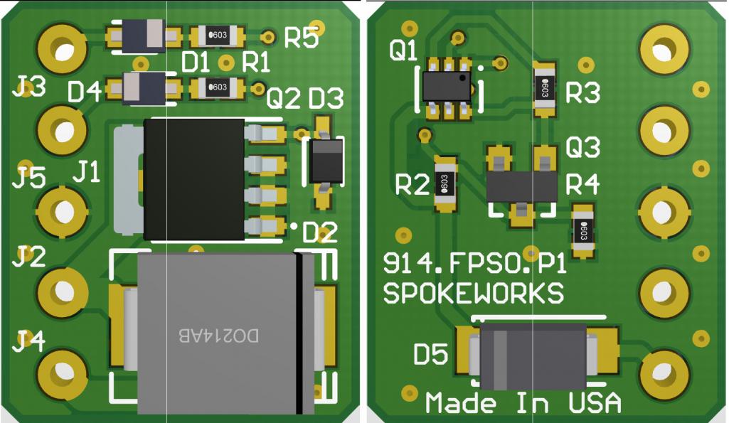
|
|
|
|
| Spoke |
Aug 7 2015, 09:02 PM
Post
#28
|
|
Jerry Group: Members Posts: 7,185 Joined: 29-October 04 From: Allentown, PA Member No.: 3,031 Region Association: None |
Got the boards back. Gotta order a few parts then assemble and test. As I mentioned before, they are tiny.
Attached thumbnail(s) 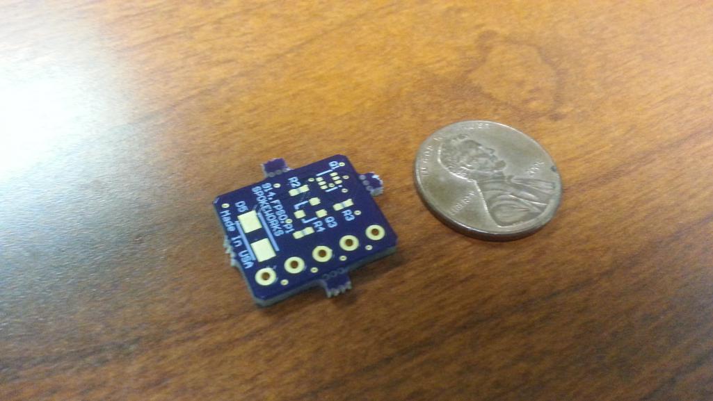
|
|
|
|
| euro911 |
Aug 7 2015, 09:22 PM
Post
#29
|
|
Retired & living the dream. God help me if I wake up! Group: Members Posts: 8,911 Joined: 2-December 06 From: So.Cal. & No.AZ (USA) Member No.: 7,300 Region Association: Southern California |
Oh, when you said they were going to be really tiny - I was thinking like, smaller than a dime (IMG:style_emoticons/default/poke.gif)
|
|
|
|
| Spoke |
Aug 8 2015, 06:26 AM
Post
#30
|
|
Jerry Group: Members Posts: 7,185 Joined: 29-October 04 From: Allentown, PA Member No.: 3,031 Region Association: None |
QUOTE(euro911 @ Aug 7 2015, 11:22 PM) Oh, when you said they were going to be really tiny - I was thinking like, smaller than a dime (IMG:style_emoticons/default/poke.gif) The power FET and catch diode pretty much determined the size of the board. I used 0603 sized resistors which are best soldered when using a microscope. (IMG:style_emoticons/default/beerchug.gif) |
|
|
|
| Spoke |
Aug 8 2015, 06:29 AM
Post
#31
|
|
Jerry Group: Members Posts: 7,185 Joined: 29-October 04 From: Allentown, PA Member No.: 3,031 Region Association: None |
QUOTE(Valy @ Jul 19 2015, 01:06 AM) Well we'll see how much this adventure costs. I like to stay true to form. I've already got $2.10 invested for the PCB alone; That's for 3 PCBs; Including shipping. |
|
|
|
| Harpo |
Aug 8 2015, 12:13 PM
Post
#32
|
|
Senior Member Group: Members Posts: 1,304 Joined: 21-August 11 From: Motor City aka Detroit Member No.: 13,469 Region Association: None |
Very nice there Jerry. I would be interested in one of these if you decide to sell them
Thanks David |
|
|
|
| andys |
Aug 8 2015, 12:56 PM
Post
#33
|
|
Advanced Member Group: Members Posts: 2,165 Joined: 21-May 03 From: Valencia, CA Member No.: 721 Region Association: None |
QUOTE(jt914-6 @ Jul 17 2015, 03:02 PM) http://www.summitracing.com/parts/sum-890145 This is what I used on my six conversion. Easy wiring and installation. That's a Ford inertia switch. I installed one on my LS1 conversion car. Make sure it's readily accessible in case you get bumped. Ford placed them in all sorts of weird places that were difficult to get to. On my Explorer, it was high up under the right side dash, on the Supercoupe, it was in the trunk. Andys |
|
|
|
| porschetub |
Aug 8 2015, 10:59 PM
Post
#34
|
|
Advanced Member Group: Members Posts: 4,875 Joined: 25-July 15 From: New Zealand Member No.: 18,995 Region Association: None |
QUOTE(Mark Henry @ Jul 19 2015, 12:44 AM) QUOTE(Valy @ Jul 18 2015, 01:12 AM) And still, my single relay circuit does the same job but its much simpler. (IMG:style_emoticons/default/agree.gif) I can't see why all this work? (IMG:style_emoticons/default/confused24.gif) Is it just to keep the relay on the board? (IMG:style_emoticons/default/wacko.gif) Again why? It's carbed so it's not like it's concours. (IMG:style_emoticons/default/poke.gif) The relay Valy posted works on oil pressure, the the relay I posted uses a simple tach input, both could be quickly stealth installed without a single OEM wire cut...so I don't get it? the whole thing has got very complicated and don't really see the point of making it to hard,bypass wired is the known method from FI to carb works is good enough,if you crash and we do ,you turn the key off......simple really. We are looking @ a low pressure supply afterall not a biggie,cheers. |
|
|
|
| mepstein |
Aug 9 2015, 04:54 AM
Post
#35
|
|
914-6 GT in waiting Group: Members Posts: 19,956 Joined: 19-September 09 From: Landenberg, PA/Wilmington, DE Member No.: 10,825 Region Association: MidAtlantic Region |
BJ's 6 conversion caught fire when the fuel pump kept running after he turned off the key. Better safe than sorry.
|
|
|
|
| SKL1 |
Aug 29 2015, 10:06 PM
Post
#36
|
|
Senior Member Group: Members Posts: 1,711 Joined: 19-February 11 From: north Scottsdale Member No.: 12,732 Region Association: Upper MidWest |
Got the Ford inertia switches for both my cars- installed one on the '73- didn't any instructions but luckily mounted it button up as I now see on their catalog page.
If you got that route, definitely get the wiring plug as it makes installation a snap. Can kind of use as a theft device but pushing the button in to turn off power to the pump. |
|
|
|
| Spoke |
Aug 30 2015, 08:26 AM
Post
#37
|
|
Jerry Group: Members Posts: 7,185 Joined: 29-October 04 From: Allentown, PA Member No.: 3,031 Region Association: None |
QUOTE(John Jentz @ Jul 18 2015, 10:33 AM) Sometimes the challenge of reinventing the wheel proves irresistible! (IMG:style_emoticons/default/agree.gif) Never be complacent with what is available. I enjoy the challenge of designing and building things. Why buy these for $5 total...  When I can buy this for $35 and have some real fun... 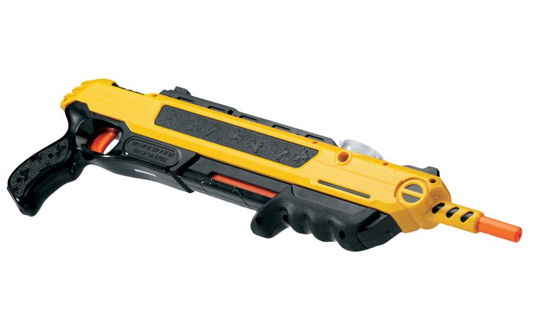 |
|
|
|
|
1 User(s) are reading this topic (1 Guests and 0 Anonymous Users)
0 Members:

|
Lo-Fi Version | Time is now: 5th July 2025 - 03:06 PM |
Invision Power Board
v9.1.4 © 2025 IPS, Inc.