|
|
|
Porsche, and the Porsche crest are registered trademarks of Dr. Ing. h.c. F. Porsche AG.
This site is not affiliated with Porsche in any way. Its only purpose is to provide an online forum for car enthusiasts. All other trademarks are property of their respective owners. |
|
|

  |

| Trekkor |
 Feb 27 2005, 10:38 AM Feb 27 2005, 10:38 AM
Post
#21
|
|
I do things...  Group: Members Posts: 7,809 Joined: 2-December 03 From: Napa, Ca Member No.: 1,413 Region Association: Northern California |
Joe, the purple/black wire is the tach wire. It now needs to come off the MSD box and go to the tach directly.
The tach wire in the dash is a better looking prurple/black due to it's being protected from the elements for so long. For my fuel pump key on power I'm using a wire off the stock relay board with no ground jumper. I use the front/right terminal on the F.I. socket. ( front right being closest to driver and engine ). Mike, this is a bit odd. Same weekend. (IMG:http://www.914world.com/bbs2/html/emoticons/unsure.gif) So, which wire gets the diode? The D+ into the relay board or the keyed 12+ power to the MSD which is shown to be the original coil+ wire? From the diagram on pg 8 of MSD manual it looks like the exciter wire needs to be diode protected so the small amont of voltage will will no longer activate the MSD which has it's own 12v constant power source. KT |
   |

 
|
| Joe Bob |
Feb 27 2005, 10:40 AM
Post
#22
|
|
Retired admin, banned a few times Group: Members Posts: 17,427 Joined: 24-December 02 From: Boulder CO Member No.: 5 Region Association: None |
Yeah the D+ wire needs it...."I" need from YOU....the rating and/or a pic of it so I can get one from Radio Crap.....it also should be directional.....which way does it say to mount it in the stoopid book?
|
|
|
|
| Trekkor |
Feb 27 2005, 10:55 AM
Post
#23
|
|
I do things... Group: Members Posts: 7,809 Joined: 2-December 03 From: Napa, Ca Member No.: 1,413 Region Association: Northern California |
Pic coming...
Take this. KT Attached image(s) 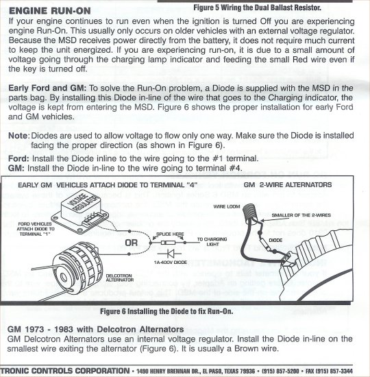
|
|
|
|
| Trekkor |
Feb 27 2005, 11:01 AM
Post
#24
|
|
I do things... Group: Members Posts: 7,809 Joined: 2-December 03 From: Napa, Ca Member No.: 1,413 Region Association: Northern California |
pic.
MSD calls it a "100V/1A diode". KT Attached image(s) 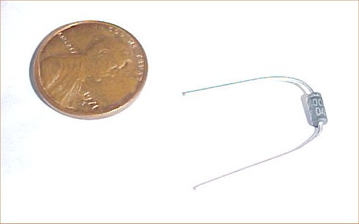
|
|
|
|
| Joe Bob |
Feb 27 2005, 11:17 AM
Post
#25
|
|
Retired admin, banned a few times Group: Members Posts: 17,427 Joined: 24-December 02 From: Boulder CO Member No.: 5 Region Association: None |
Thanks....
|
|
|
|
| Trekkor |
Feb 27 2005, 02:57 PM
Post
#26
|
|
I do things... Group: Members Posts: 7,809 Joined: 2-December 03 From: Napa, Ca Member No.: 1,413 Region Association: Northern California |
So can just place the diode in-line before the charge light in the dash behind the guage?
KT |
|
|
|
| Aaron Cox |
Feb 27 2005, 02:57 PM
Post
#27
|
|
Professional Lawn Dart Group: Retired Admin Posts: 24,542 Joined: 1-February 03 From: Corona, CA Member No.: 219 Region Association: Southern California |
i believe you want the diode inline with the switched hot to the box (form your IGN switch) thats what my bok says anyway (IMG:http://www.914world.com/bbs2/html/emoticons/blink.gif)
|
|
|
|
| Sparky |
Feb 27 2005, 03:09 PM
Post
#28
|
|
Mahna Mahna! Group: Members Posts: 1,134 Joined: 21-June 03 From: Spencer, MA Member No.: 847 |
Gee or read the manual they actually tell you that you may need to use an early Chrysler ballast resistor as part of the install. Had to do this on the 944.
Mike D. |
|
|
|
| Trekkor |
Feb 27 2005, 03:09 PM
Post
#29
|
|
I do things... Group: Members Posts: 7,809 Joined: 2-December 03 From: Napa, Ca Member No.: 1,413 Region Association: Northern California |
the MSD paperwork ( above ) reads differently.
KT |
|
|
|
| Joe Bob |
Feb 27 2005, 04:13 PM
Post
#30
|
|
Retired admin, banned a few times Group: Members Posts: 17,427 Joined: 24-December 02 From: Boulder CO Member No.: 5 Region Association: None |
Just did the install....it works...
|
|
|
|
| Trekkor |
Feb 27 2005, 04:45 PM
Post
#31
|
|
I do things... Group: Members Posts: 7,809 Joined: 2-December 03 From: Napa, Ca Member No.: 1,413 Region Association: Northern California |
Where did you put the diode, Mike, I want to do this tomorrow?
KT |
|
|
|
| Aaron Cox |
Feb 27 2005, 06:39 PM
Post
#32
|
||
|
Professional Lawn Dart Group: Retired Admin Posts: 24,542 Joined: 1-February 03 From: Corona, CA Member No.: 219 Region Association: Southern California |
put a set of male and female terminals on the diod and do it right at the indicator is my guess (IMG:http://www.914world.com/bbs2/html/emoticons/wink.gif) (no cutting or splicing necessary if you solder termianls onto the diode (IMG:http://www.914world.com/bbs2/html/emoticons/smile.gif) |
||
|
|
|
||
| Joe Bob |
Feb 27 2005, 07:14 PM
Post
#33
|
|
Retired admin, banned a few times Group: Members Posts: 17,427 Joined: 24-December 02 From: Boulder CO Member No.: 5 Region Association: None |
Put it on the D+ lead to the bulb.....had a 50/50 chance of fucking it up...did it right the first time...it's directional....
|
|
|
|
| Trekkor |
Feb 28 2005, 03:13 PM
Post
#34
|
|
I do things... Group: Members Posts: 7,809 Joined: 2-December 03 From: Napa, Ca Member No.: 1,413 Region Association: Northern California |
50/50 HUH? Not so good odds.
I NEED the real story! (IMG:http://www.914world.com/bbs2/html/emoticons/blink.gif) I want the electricity to go one way, to the bulb, right? KT |
|
|
|
| Trekkor |
Feb 28 2005, 04:08 PM
Post
#35
|
|
I do things... Group: Members Posts: 7,809 Joined: 2-December 03 From: Napa, Ca Member No.: 1,413 Region Association: Northern California |
Got it!
Crimped on a terminal to each end with heat shrink between 'em. Works great. No more run on. (IMG:http://www.914world.com/bbs2/html/emoticons/clap.gif) KT Still need to open up the plug gaps (IMG:http://www.914world.com/bbs2/html/emoticons/dry.gif) |
|
|
|
| Joe Bob |
Jun 20 2005, 08:57 AM
Post
#36
|
|
Retired admin, banned a few times Group: Members Posts: 17,427 Joined: 24-December 02 From: Boulder CO Member No.: 5 Region Association: None |
So how come this never went to the classic threads?
|
|
|
|
|
1 User(s) are reading this topic (1 Guests and 0 Anonymous Users)
0 Members:

|
Lo-Fi Version | Time is now: 31st August 2025 - 06:14 AM |
Invision Power Board
v9.1.4 © 2025 IPS, Inc.