|
|
|
Porsche, and the Porsche crest are registered trademarks of Dr. Ing. h.c. F. Porsche AG.
This site is not affiliated with Porsche in any way. Its only purpose is to provide an online forum for car enthusiasts. All other trademarks are property of their respective owners. |
|
|

  |

| mepstein |
 May 24 2017, 08:38 PM May 24 2017, 08:38 PM
Post
#161
|
|
914-6 GT in waiting  Group: Members Posts: 20,295 Joined: 19-September 09 From: Landenberg, PA/Wilmington, DE Member No.: 10,825 Region Association: MidAtlantic Region |
I just came across this - http://zerodecibelmotorsports.com/products...mechanism-5spd/
Not cheap at $300 but an option if coldwater isn't going to make more shifter kits. Attached image(s) 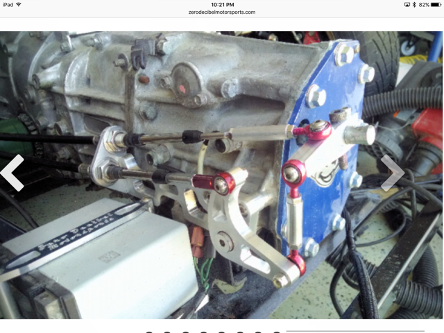
|
   |

 
|
| jimkelly |
May 24 2017, 08:55 PM
Post
#162
|
|
Delaware USA Group: Members Posts: 4,969 Joined: 5-August 04 From: Delaware, USA Member No.: 2,460 Region Association: MidAtlantic Region |
wow, nice.
seems gate for 5th and reverse is spring loaded,and i am having some issues. 1st and 2nd not. not sure i was really in 5th and reverse. pushing forward on shifter feels better engagement, than pulling back. also feels like it wants to jump past neutral and on to next gear in same gate but maybe it is just a matter of getting used to it? https://www.youtube.com/watch?v=zE_UYPzY8Ss |
|
|
|
| jimkelly |
May 26 2017, 04:24 PM
Post
#163
|
|
Delaware USA Group: Members Posts: 4,969 Joined: 5-August 04 From: Delaware, USA Member No.: 2,460 Region Association: MidAtlantic Region |
seems like a good price for push pull cables on ebay.
I mention this cause there seems to be empirical data suggesting that shifting the gates is done much better using a long cable coming to trans from the side. ie: dbcooper and many others. so I think one 90" and one 120" are probably the best cable lengths to use. ref: http://www.914world.com/bbs2/index.php?showtopic=102887 search this: Steinjager Shifter Cables, Push-Pull 1/4-28 90 Inches Long Bulkhead Style or Steinjager Shifter Cables, Push-Pull 1/4-28 120 Inches Long Bulkhead Style Attached image(s) 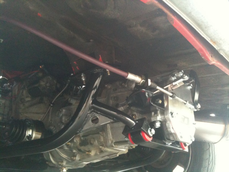
|
|
|
|
| 76-914 |
May 26 2017, 07:35 PM
Post
#164
|
|
Repeat Offender & Resident Subaru Antagonist Group: Members Posts: 13,830 Joined: 23-January 09 From: Temecula, CA Member No.: 9,964 Region Association: Southern California |
Jim, if your going this route check my build thread. I listed the lengths there, Maybe it was 9' & 7.5' but I'm not sure. Less moving parts = reliability! (IMG:style_emoticons/default/beerchug.gif)
|
|
|
|
| Amenson |
May 27 2017, 08:01 AM
Post
#165
|
|
That's opposite lock!! Group: Members Posts: 645 Joined: 27-May 05 From: Dublin, OH Member No.: 4,154 Region Association: None |
QUOTE(jimkelly @ May 24 2017, 09:55 PM)  wow, nice. seems gate for 5th and reverse is spring loaded,and i am having some issues. 1st and 2nd not. not sure i was really in 5th and reverse. pushing forward on shifter feels better engagement, than pulling back. also feels like it wants to jump past neutral and on to next gear in same gate but maybe it is just a matter of getting used to it? https://www.youtube.com/watch?v=zE_UYPzY8Ss There is a lockout for reverse so you can't go from fifth to reverse until returning to the 3/4 location. Looks like that was your issue. |
|
|
|
| jimkelly |
May 27 2017, 08:00 PM
Post
#166
|
|
Delaware USA Group: Members Posts: 4,969 Joined: 5-August 04 From: Delaware, USA Member No.: 2,460 Region Association: MidAtlantic Region |
son of a gun (IMG:style_emoticons/default/smile.gif) thanks (IMG:style_emoticons/default/biggrin.gif)
|
|
|
|
| jimkelly |
May 28 2017, 01:30 PM
Post
#167
|
|
Delaware USA Group: Members Posts: 4,969 Joined: 5-August 04 From: Delaware, USA Member No.: 2,460 Region Association: MidAtlantic Region |
i'm starting to wonder if this cradle (sawtooth's) could be made even simpler with long sections reaching all the way to the trans hanger section. I also wonder if the cross bar needs some amount of bump up to allow easier passage for exhaust.
http://www.914world.com/bbs2/index.php?sho...p;#entry1404662 though I see lots of guys doing turbo thus turbo routed exhausts. though sawtooth's header solution seems to fit beautifully. Attached image(s) 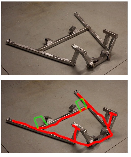
|
|
|
|
| jimkelly |
May 29 2017, 08:17 PM
Post
#168
|
|
Delaware USA Group: Members Posts: 4,969 Joined: 5-August 04 From: Delaware, USA Member No.: 2,460 Region Association: MidAtlantic Region |
picked up a 1997 legacy 5spd awd trans today for $100. it has the 2 bungs on its side.
|
|
|
|
| jimkelly |
May 30 2017, 02:35 PM
Post
#169
|
|
Delaware USA Group: Members Posts: 4,969 Joined: 5-August 04 From: Delaware, USA Member No.: 2,460 Region Association: MidAtlantic Region |
guess i'll buy a microsquirt harness and start wiring it up. relays and ignition switch and all. guess i'll start by writing down all the colors of the wires that come out of all my sensors, injectors, etc, and figure out what goes where.
here is an image of many of my plugs. Attached thumbnail(s) 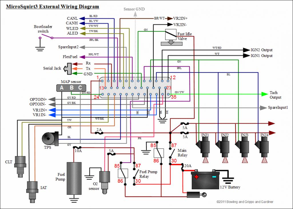 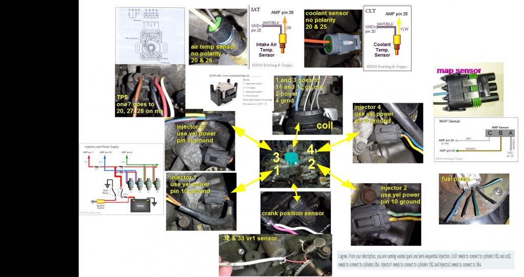
|
|
|
|
| jimkelly |
May 31 2017, 04:55 PM
Post
#170
|
|
Delaware USA Group: Members Posts: 4,969 Joined: 5-August 04 From: Delaware, USA Member No.: 2,460 Region Association: MidAtlantic Region |
i think this brit is giving me the correct firing order of the coil?
https://www.youtube.com/watch?v=XgJy-mJ2xyE and ordered a shift knob 12mm 1.25 $12 ebay Attached image(s) 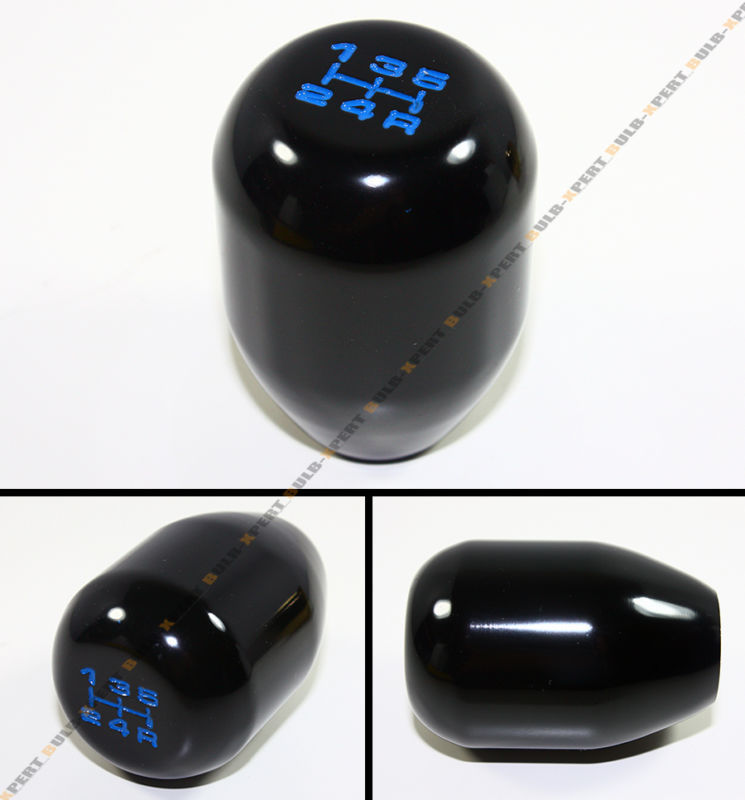
|
|
|
|
| jimkelly |
Jun 7 2017, 11:23 AM
Post
#171
|
|
Delaware USA Group: Members Posts: 4,969 Joined: 5-August 04 From: Delaware, USA Member No.: 2,460 Region Association: MidAtlantic Region |
guys. i know you are some smart fellas. how do i check this vw coil to figure out what spark plug wire holes are on each bank and figure out what electrical pins are for each bank?
is there some sort of continuity test i can do that won't cause possible damage to the coil? also, my plug to the coil has one fat wire NOT at the 12v supply pin. i should probably move it to the 12v supply pin, right? Attached thumbnail(s) 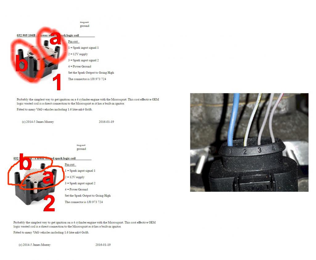
|
|
|
|
| jimkelly |
Jun 9 2017, 11:42 AM
Post
#172
|
|
Delaware USA Group: Members Posts: 4,969 Joined: 5-August 04 From: Delaware, USA Member No.: 2,460 Region Association: MidAtlantic Region |
with or without you guys, i am gonna figure out, the pin out, of my tps. then i need to figure out the pin out and the spark out of my vw coil (IMG:style_emoticons/default/idea.gif)
Attached thumbnail(s) 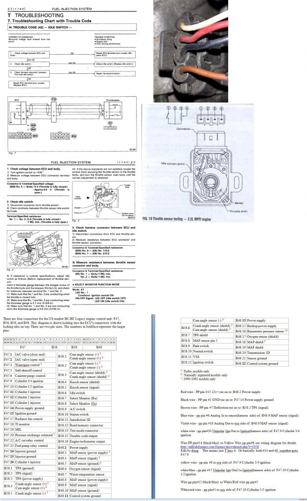
|
|
|
|
| timothy_nd28 |
Jun 9 2017, 12:43 PM
Post
#173
|
|
Advanced Member Group: Members Posts: 2,299 Joined: 25-September 07 From: IN Member No.: 8,154 Region Association: Upper MidWest |
Looks like the TPS pin 2 ties to the microsquirts gnd and pin 3 ties to the microsquirts 5v ref. That leaves you with pin 4 that goes to the microsquirts TPS signal wire. Looks like pin 1 will not be used, its a idle switch that the microsquirt doesn't support.
Toward the ignition coil, I would bench test this to see what's what. It looks like the coil needs a pull up signal to fire a certain bank. I would use a car battery to supply the 12volts to the coil, and also have the microsquirt powered up so you could temporarily borrow its 5volt ref voltage to tap either bank 1 or bank 2 signal input, then observe which banks fire. |
|
|
|
| jimkelly |
Jun 9 2017, 12:56 PM
Post
#174
|
|
Delaware USA Group: Members Posts: 4,969 Joined: 5-August 04 From: Delaware, USA Member No.: 2,460 Region Association: MidAtlantic Region |
thank you (IMG:style_emoticons/default/smile.gif)
Attached thumbnail(s) 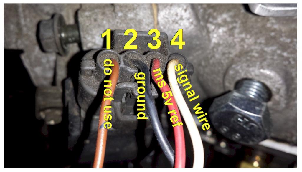
|
|
|
|
| timothy_nd28 |
Jun 9 2017, 01:07 PM
Post
#175
|
|
Advanced Member Group: Members Posts: 2,299 Joined: 25-September 07 From: IN Member No.: 8,154 Region Association: Upper MidWest |
TPS pin 1---not used
TPS pin 2 ties to Microsquirts pin 20 (GND) TPS pin 3 ties to Microsquirts pin 28 (5v ref) TPS pin 4 ties to Microsquirts pin 27 (tps signal) You may want to verify this by following the instructions here:  |
|
|
|
| jimkelly |
Jun 9 2017, 01:23 PM
Post
#176
|
|
Delaware USA Group: Members Posts: 4,969 Joined: 5-August 04 From: Delaware, USA Member No.: 2,460 Region Association: MidAtlantic Region |
tim, i will.
next up, the vw coil. diy provides this for pin out put i don't know which two spark holes are paired and i don't know which two are 1-3 and 3-4. MY BAD, DIY DOES PROVIDE MORE INFO ON COIL. http://www.msextra.com/doc/pdf/html/Micros...are-3.4-62.html http://www.msextra.com/doc/pdf/html/Micros...are-3.4-63.html Attached thumbnail(s) 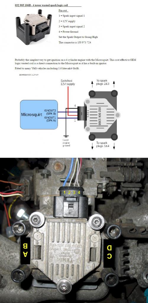
|
|
|
|
| jimkelly |
Jun 9 2017, 02:29 PM
Post
#177
|
|
Delaware USA Group: Members Posts: 4,969 Joined: 5-August 04 From: Delaware, USA Member No.: 2,460 Region Association: MidAtlantic Region |
revised collage
Attached thumbnail(s) 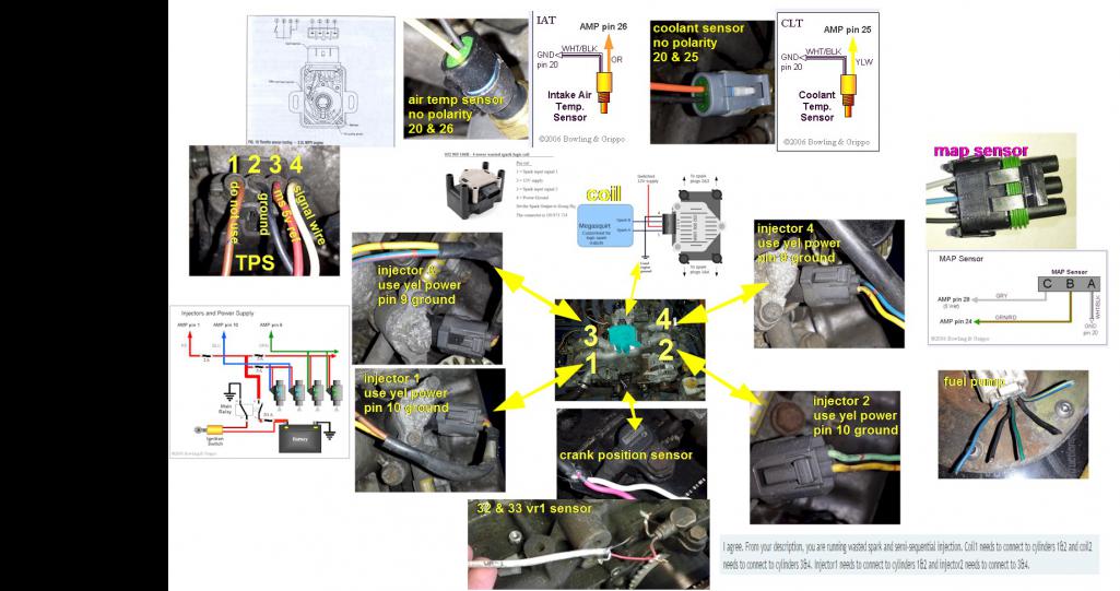
|
|
|
|
| timothy_nd28 |
Jun 9 2017, 02:47 PM
Post
#178
|
|
Advanced Member Group: Members Posts: 2,299 Joined: 25-September 07 From: IN Member No.: 8,154 Region Association: Upper MidWest |
are you setting up both crank and cam signals? Does microsquirt allow both functions?
|
|
|
|
| jimkelly |
Jun 9 2017, 02:59 PM
Post
#179
|
|
Delaware USA Group: Members Posts: 4,969 Joined: 5-August 04 From: Delaware, USA Member No.: 2,460 Region Association: MidAtlantic Region |
not sure if it allows for both but i am not using a cam sensor. not needed as i understand it.
i did just notice a conflict on what pins to use for the cylinders on diy microsquirt page. http://www.useasydocs.com/details/wire.htm Attached image(s) 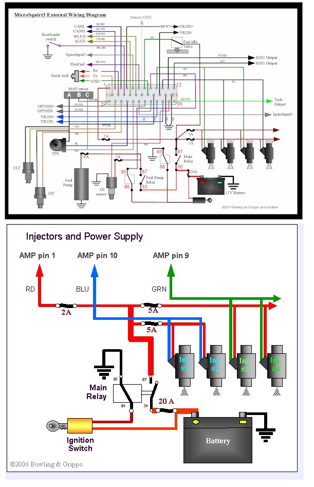
|
|
|
|
| timothy_nd28 |
Jun 9 2017, 03:11 PM
Post
#180
|
|
Advanced Member Group: Members Posts: 2,299 Joined: 25-September 07 From: IN Member No.: 8,154 Region Association: Upper MidWest |
you can solve this discrepancy by buying the sequential injection upgrade kit (IMG:style_emoticons/default/biggrin.gif)
|
|
|
|
|
1 User(s) are reading this topic (1 Guests and 0 Anonymous Users)
0 Members:

|
Lo-Fi Version | Time is now: 20th December 2025 - 04:09 AM |
Invision Power Board
v9.1.4 © 2025 IPS, Inc.