|
|
|
Porsche, and the Porsche crest are registered trademarks of Dr. Ing. h.c. F. Porsche AG.
This site is not affiliated with Porsche in any way. Its only purpose is to provide an online forum for car enthusiasts. All other trademarks are property of their respective owners. |
|
|


| radobard |
 Feb 3 2016, 10:19 AM Feb 3 2016, 10:19 AM
Post
#1
|
|
Newbie  Group: Members Posts: 2 Joined: 15-January 16 From: San Antonio, TX Member No.: 19,563 Region Association: None |
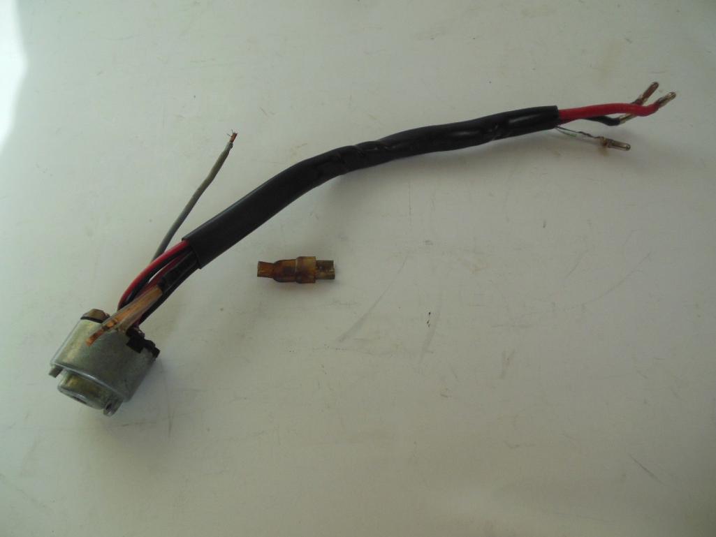
I just replaced my ignition switch on my 1970 porsche 914 4. The replacement switches have four wires connected , red, red/white, black, and grey. My original switch had five wires, red, red/black, black, grey, and a copper see through wire. First question, does the red/ white wire on the original replace the red/black wire on the new? Second question, what is the function of the copper see through wire? If I don't have it in the replacement switch, will something not work? Here is a photo of an original switch with the five wires. The see through copper looking wire is at the top.
 |
   |

 
|
  |
Replies
| 3d914 |
Feb 3 2016, 09:08 PM
Post
#2
|
|
Senior Member Group: Members Posts: 1,275 Joined: 24-September 03 From: Benson, AZ Member No.: 1,191 Region Association: Southwest Region |
The image below shows the switch (26) on the schematic.
Red wire (#30 at connection #12) goes to the fuse box (Fuse 11), the main light switch, and battery positive. This should be a thick wire. White wire (#34) appears to go to the adjacent signal switch in the column. Red/White wire (#35 at connection 13) also goes to the light switch. Black wire (#15 at connection 8) goes to fuse box (Fuse 8) and to the rear relay board in the large connector at pin 8. Yellow wire (#36 at connection 10) also goes to the rear relay board in the large connector at pin 1. Doesn't look like you can do without any of these. Haynes has a good manual for the 914 with all the schematics. May prove helpful. 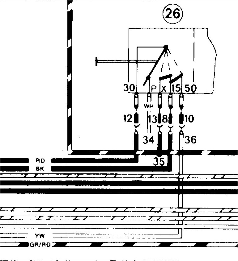 |
|
|
|
| pdlightning |
Feb 3 2016, 10:47 PM
Post
#3
|
|
Member Group: Members Posts: 207 Joined: 4-February 11 From: Santa Clarita Member No.: 12,660 Region Association: Southern California |
QUOTE(3d914 @ Feb 3 2016, 07:08 PM)  The image below shows the switch (26) on the schematic. Red wire (#30 at connection #12) goes to the fuse box (Fuse 11), the main light switch, and battery positive. This should be a thick wire. White wire (#34) appears to go to the adjacent signal switch in the column. Red/White wire (#35 at connection 13) also goes to the light switch. Black wire (#15 at connection 8) goes to fuse box (Fuse 8) and to the rear relay board in the large connector at pin 8. Yellow wire (#36 at connection 10) also goes to the rear relay board in the large connector at pin 1. Doesn't look like you can do without any of these. Haynes has a good manual for the 914 with all the schematics. May prove helpful. Does that mean the replacement switch doesn't have enough wires? All of the replacement switches I have seen for the 70-71 4 cyls have only four wires. The 6 cyls have a reg 911 multi pin replacement switch. |
|
|
|
Posts in this topic
 radobard 1970 porsche 914 ignition switch wiring Feb 3 2016, 10:19 AM
 McMark The see-thru wire looks like a ground. I'd us... Feb 4 2016, 09:00 AM
 mark04usa
The see-thru wire looks like a ground. I'd u... Feb 4 2016, 12:04 PM radobard Where does this ground wire connect within the ign... Feb 11 2016, 11:19 PM McMark According to the picture posted above, the clear g... Feb 12 2016, 09:54 AM porsche913b_sp I would like to know also where the see thru groun... Feb 26 2016, 06:28 PM Jeff Bowlsby That clear jacketed solid flat copper conductor go... Feb 28 2016, 12:05 AM 914Mike
That clear jacketed solid flat copper conductor g... Feb 28 2016, 12:49 PM mark04usa
That clear jacketed solid flat copper conductor g... Feb 29 2016, 02:08 AM Jeff Bowlsby :D Mar 2 2016, 11:47 AM porsche913b_sp Wow that's great information. I appreciate it.... Mar 2 2016, 09:06 PM raynekat Just to resurrect an old thread and question.
The... May 12 2017, 01:56 PM
mark04usa
The see-thru wire looks like a ground. I'd u... Feb 4 2016, 12:04 PM radobard Where does this ground wire connect within the ign... Feb 11 2016, 11:19 PM McMark According to the picture posted above, the clear g... Feb 12 2016, 09:54 AM porsche913b_sp I would like to know also where the see thru groun... Feb 26 2016, 06:28 PM Jeff Bowlsby That clear jacketed solid flat copper conductor go... Feb 28 2016, 12:05 AM 914Mike
That clear jacketed solid flat copper conductor g... Feb 28 2016, 12:49 PM mark04usa
That clear jacketed solid flat copper conductor g... Feb 29 2016, 02:08 AM Jeff Bowlsby :D Mar 2 2016, 11:47 AM porsche913b_sp Wow that's great information. I appreciate it.... Mar 2 2016, 09:06 PM raynekat Just to resurrect an old thread and question.
The... May 12 2017, 01:56 PM |
1 User(s) are reading this topic (1 Guests and 0 Anonymous Users)
0 Members:

|
Lo-Fi Version | Time is now: 24th May 2024 - 04:42 PM |
Invision Power Board
v9.1.4 © 2024 IPS, Inc.