|
|
|
Porsche, and the Porsche crest are registered trademarks of Dr. Ing. h.c. F. Porsche AG.
This site is not affiliated with Porsche in any way. Its only purpose is to provide an online forum for car enthusiasts. All other trademarks are property of their respective owners. |
|
|

  |

| Cap'n Krusty |
 Apr 6 2005, 07:19 PM Apr 6 2005, 07:19 PM
Post
#1
|
|
Cap'n Krusty  Group: Members Posts: 10,794 Joined: 24-June 04 From: Santa Maria, CA Member No.: 2,246 Region Association: Central California |
Here we go! Somebody hold my beer! The Cap'n, with thanks to Jim Thorusen, DDD, and others.
First, general rules: Be sure that you use the correct clearance values for your engine: .006 INTAKE... .008 EXHAUST (for 2.0 liter) ( .006 BOTH for 1.7 liter). SOME 1.8s that were rebuilt in the '70s and '80s MAY have sodium filled exhaust valves fitted and would use the .008" setting! Don't mix them up! As a general rule of thumb, exhaust valves run hotter than intake valves, therefore they lengthen more due to expansion, therefore the larger clearance specification will be for the exhaust valve. I'm sure that someone can site an example of it being the other way around, and of course there are engines (including the 914 1.7 litre) that have identical clearances for both, but as I said, it's a rule of thumb. If you set a valve .001" looser than spec, it might be a bit noisier, but you will not harm anything. Setting an exhaust valve .002" too tight will risk burning it... not a good idea, so to reiterate: .006" INTAKE .008" EXHAUST. Now, if you exert sufficient force on a feeler gauge, for anything but big gnarly racing engines you can actually open the valve with the gauge, as you have considerable mechanical advantage owing to the curved shape of the end of the rockers. A correctly adjusted valve will put a slight amount of drag on the feeler gauge as it is moved back and forth. If the gauge slips in with no resistance at all, the valve is too loose. If you have to strain, and the feeler gauge feels like it wants to sproing into an inchworm shape instead of going in, the valve is too tight. There should be just a little bit of drag on the gauge; enough so that you can detect a friction effect, even with oil present. Once you have this feel in mind, stick in the appropriate gauge and measure the clearance... as in fortran, you have three choices: < > or =. Once you have determined which way you need to go, loosen the lock nut, turn the screw a bit in the correct direction, and re-tighten the lock nut. Note that when you tighten the lock nut, the adjusting screw sets back into the rocker arm, commonly by as much as .001", so allow for this when tightening, and let the adjusting screw turn SLIGHTLY clockwise with the lock-nut. Repeat the adjustment as necessary until the clearance is correct; i.e. slight drag on the feeler gauge with ALL TOOLS OFF THE VALVE TRAIN! There should never be any tool on the rocker assembly, either screwdriver or wrench, while actually measuring the clearance. You will introduce side loads or other moments that will prevent an accurate measurement. Now for the actual adjustment procedure. To understand it, however, a bit of history and theory first. I should like to point out that the 914-4 engine is a derivative of the good old VW engine designed by Dr. Porsche way back when. As the "people's car" everything, including the engine, was designed for cheap mass production. As part of this philosophy, Dr. Porsche reasoned (I take license here) something like this: "Why should I design a typical 4-cylinder engine camshaft with 8 lobes, when I can get by with half that number?" Due to the flat-four layout, each cam lobe does double duty, actuating a valve first on one side of the engine, and then on the other. This then gives rise to a simplified adjustment procedure, which I have printed up and glued into my Haynes manual to replace the rather cumbersome procedure in the book. It works perfectly. I quote verbatim: 1. Jack up car and place on stands; block one rear road wheel to prevent it's turning, engage 5th gear, handbrake off. 2. Valve clearances are adjusted with the engine COLD. Clearances are INTAKE = .006" EXHAUST = 008". ('74 model year, 2.0 litre engine) Remove valve covers, clean up spilled oil, and check gaskets; renew if necessary. 3A. Using the unblocked road wheel as a hand wheel, rotate the engine until the rockers are rocking in accordance with the first entry in the table below. Adjust the clearances of the corresponding valves as shown in the table. Continue rotating engine and adjusting valves until all have been done. Re-install valve covers. 3B.As an alternative, a momentary starter button connected between the starter post and the activation terminal may be used. BE SURE the car is out of gear if using this method! 4. Valve adjustment table: # denotes cylinder number; Ex = Exhaust valve; In = Intake valve. Turn until Rocking: Adjust: #2 Ex & #3 In #4 Ex & #1 In #1 Ex & #2 In #3 Ex & #4 In #4 Ex & #1 In #2 Ex & #3 In #3 Ex & #4 In #1 Ex & #2 In 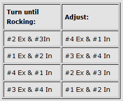 It follows logically that a valve opposite one that is open is on the back of the same cam lobe, the perfect place for adjustment. It is only necessary to be certain of which valves actually share the same cam lobe, which can be a little tricky owing to the offset nature of the cylinder layout. However, I believe that I have done this, and that further, I have worked it out so that, if the valves are adjusted in the order given in the table, a minimum amount of engine rotation will be necessary to complete the task. One other helpful hint: Unless you are VERY familiar with the engine layout, clean two spots on the bottom of each head next to the pair of valves associated with each cylinder and mark the cylinder number in the cleaned spots with magic marker so that it can be seen from under the car. This will help you figure out which cylinder is which while you are upside down under the car, and is an invaluable aid in using the table. The cylinder layout can be taken from fig. 3.3 on page 63 of the Haynes book, or, if the engine is clean enough, can be taken from stamped numbers in the engine sheet metal. Good Luck, Jim T. __________________ ********************************* The following is a reply to some folks who had trouble understanding what I meant when I used the term "rocking"..... They wrote back to tell me that the job went easily after this clarification. __________________ Hello, Gene & Tony! You wrote: <snip> " My son and I just bought a 1973 914 1700 and did our first valve adjustment on it today--it didn't talke us too long but it would have been a real bear with just one person. We're NOT totally new to this type of motor--my son drives a 1973 1700 VW Campmobile--and also not new to the valve adjustment scene. However I was quite intrigued by your approach and would love to try it, but I can't figure out a few things. I hope I my questions aren't too obtuse. Here goes: I'm assuming one can adjust the valves BY HIMSELF without paying attention to timing marks or top dead center, etc., by using the 'rocking' technique, i.e. " Yes.... it is a one-person job if you do it this way.... and further, when you get to be as old and as fat as I am, you will appreciate the fact that you don't have to get up off your creeper until you're finished. :-) <snip> " What does this mean--Rocking--and how to you know when you're in a position to do the first set of adjustments, which is: "#2 Ex & #3 In #4 Ex & #1 In" " Well.... not quite. I see by your enclosure that the table of adjustments was distorted by the time you got it... I have reproduced it with the spaces that need to be in it below: Turn until Rocking: Adjust: #2 Ex & #3 In #4 Ex & #1 In #1 Ex & #2 In #3 Ex & #4 In #4 Ex & #1 In #2 Ex & #3 In #3 Ex & #4 In #1 Ex & #2 In First, a definition of the term "rocking". The name that is usually applied to the levers that convert the direction of travel of the pushrod (out) to valve motion (in) is "rocker arms". Therefore, by definition, rocker arms "rock", or pivot about the "rocker shaft", the gizmo that they are mounted on. So "rocking" is observed movement of the rocker arm for the valves mentioned in the first column of the table. Once you have the PAIR of valves in the FIRST column of the table open (rocker arms rocking, rather than in valve closed position) it is then correct to adjust the CORRESPONDING PAIR of valves in the SECOND column of the table (on the same line, or row of the table). In other words, you would rotate the engine (by turning the road wheel with the car in gear) until the # 2 exhaust and the # 3 intake valves were observed to open (observed motion of their rockers). When you have both of these valves open, you can then proceed to adjust # 4 exhaust and # 1 intake. This completes the first line of the table, and you have two valves adjusted. You then proceed to the next line of the table, and look for motion of the "que" or "indicator" valves in the first column, and adjust the valves in the second column. This process continues until you have completed all four lines in the table, adjusting two valves per line. " ,,,now I'm again assuming what this means is that when you get the valves in the position above, you can adjust these four valves: #2 exhaust, #3 intake, #4 exhaust, and #1 intake--right? " No, only two at a time; see above. <snip> " So, please enlighten me on where I"m having difficulty understanding, and definitely tell me how to recognize when I"ve 'rocked' right to begin the adjustments. Oh, BTW (by the way), as I'm looking at the #1 and #2 side of the valve rockers, underneath the car, with #1 being to the left, which is the intake valve, the 1st or the 2nd? " The cylinder layout is pictured on page 63 of the Haynes book; fig. 3.3. The intake valves are the pair in the center of the heads; the exhaust valves are the outermost valves. The engine layout is such that the valve layout for the LEFT side of the car is as follows (from front to rear): # 2 Ex # 2 In # 1 In # 1 Ex and on the RIGHT side of the car, from front to rear: # 4 Ex # 4 In # 3 In # 3 Ex I have taken the liberty of adding some theory on the mechanical layout of the flat-four, and why this method works. This was posted to the list to answer some questions similar to yours. I hope it helps. From my files: It is necessary to use the table of valves that I include; note that in NO case are the two valves that are rocking at the same time associated with the same cylinder. Turn until Rocking: Adjust: #2 Ex & #3 In #4 Ex & #1 In #1 Ex & #2 In #3 Ex & #4 In #4 Ex & #1 In #2 Ex & #3 In #3 Ex & #4 In #1 Ex & #2 In The reason was detailed in the complete procedure that I posted, but perhaps it was not clear. Given that the best place to adjust valve clearance is when the lifter (follower, tappet, whatever you prefer) is on the BACK or circular part of the cam lobe, i.e. opposite to the bump, then the problem simply becomes one of positioning the cam so that it's back side is adjacent to the lifter of the valve that we wish to adjust. Because of the valve train layout of the flat-four, this is most easily done. If you have a Haynes book, look at the illustration on page 26. Near the bottom of the page is a pretty good picture of the 914 cam shaft. Count the lobes. You will observe that there are only four... but the engine has eight valves! The VW flat four is the only engine that I know of to use this unique layout. The camshaft has two exhaust lobes, and two intake lobes. Each lobe actuates two valves on opposite sides of the engine; thus we can operate 8 valves with only 4 cam lobes. However, this brings up an interesting observation: If a particular exhaust valve, for example, on the right side of the engine is open, then it must be that the opposite exhaust valve is fully closed; i.e. it's lifter is on the exact opposite side of the cam lobe from the "bump". Referring back to our "given" above, this is the perfect place to adjust the valve OPPOSITE to the one that is open. If you look at figure 3.3 on page 63 of the Haynes book, you will see the engine cylinder layout. The first entry in my table says: turn until rocking - # 2 exhaust and # 3 intake. If you look at the engine layout, you will note that the exhaust valve for # 4 is opposite to # 2 (the one that is open), and likewise the intake for # 1 is opposite to # 3 (the open intake valve). Therefore, at this point, we should logically adjust # 4 exhaust and # 1 intake, and referring to the table, that's exactly what it says. The rest of the table was derived simply by turning the engine in it's normal direction of rotation and observing which valve pairs rocked together next, and then noting their opposites to be adjusted. Regards, Jim T. _____________________ ************************************************* The following is part of a discussion that Dave Darling and I had on this method eons ago. I'm sure that you recall that this argument surfaced again recently. I do not recall exactly who I had the discussion with, and the thread is long gone due to a virus attack. The last thing I posted was a set of quotes from various shop manuals illustrating the use of the back of the cam for valve adjustment. The individual wrote back that the examples I used (Alfa Romeo, MGA Twincam, and MGB were not relevant, because they were high-performance engines, or some such silly reason. It was obvious from the reply that the individual involved was weak in his understanding of geometry, the list in general was begging that the thread be allowed to die, and I got hit with two viruses the next day, so I just let it pass. The following is Dave's experience, which is a bit more relevant, I believe, and my reply to him. ____________________________ For Dave D.; cc porscheFans-914 Dave writes: > I feel compelled to point out here that Jim and I disagree > a bit about valve adjusting procedures. > On my 2.0 motor, shortly before its rebuild, I measured the > valve clearance on an exhaust valve while the intake valve on that > same cylinder was open. It was larger than it should have been. I just want to be sure that we are in agreement as to what my procedure calls for; the valve that would be rocking in the case you mention would not be the intake valve of the same cylinder, but the EXHAUST valve of the OPPOSITE cylinder. > Then I rotated the engine until that cylinder was at TDC--both > valves were closed, and the fan mark was either at top or bottom (I > forget which cylinder). The measurement was on spec. > When I asked, I got two replies (Stan Hanks and AA's George > Hussey) that indicated that the geometry of the valve train could > increase the valve clearance at some points along the camshaft's > rotation. I would like a more detailed explanation of how this could be... a camshaft lobe consists of two geometrical figures (in simplified terms): a circle, and a triangle. For most of it's rotation (assuming that the camshaft is in good shape) the follower is riding on the circle, and the valve train geometry is static... the only change that could result in a clearance change is the degree of out-of-roundness or roughness of the cam itself.*** For the rest of the rotation, of course, the triangular-shaped portion of the cam drives the valve open. The more radical the cam, the more the "triangle" departs from that shape, and the smaller the arc on the back of the cam that remains circular. For this reason, to avoid having to take into account cam grind parameters, the standard place to measure valve clearance is on the part of the cam EXACTLY opposite to the peak of the lobe. In a DOHC engine this is easy to do, since you are looking right at the cams with the valve cover off, and you can rotate the engine until the cam lobe points straight away from the valve. In a pushrod engine, where the cam is invisible, some other method must be employed to ensure that you are on the back of the lobe. The infallible method (as well as the most tedious) is to rotate the engine until the valve that you wish to adjust is at the point of maximum opening. Then mark the flywheel (or fan, maybe in the case of the 914) and rotate the engine exactly one revolution. At this point, you will be exactly on the back of the lobe, and the adjustment can be made. Needless to say, this is extremely time consuming, and except in the case of the most radical grind cams, is not necessary. The procedures for valve adjustment for an MGB, an Isuzu, and a Nissan all call for adjusting certain valves with certain other valves rocking. This can be done because the manufacturer knows how far around the cam the circular part extends, and thus how far off from the exact back of the lobe adjustment is permissible. Also, it is true that it is possible to come very close to the exact back of the lobe for some valves with some other valves rocking, simply owing to the nature of the valve timing for a particular engine. In the case of the flat-four, we have a unique valve layout that readily allows us to find the point opposite to the peak of the lobe. This is because the same cam lobe operates a valve first on one side of the engine, and then on the other. For example, when the exhaust valve on cylinder # 2 is open, the exhaust valve on cylinder # 4 is as closed as it's going to get, because the tappets for both valves are riding on the SAME cam lobe, 180 degrees apart. Hence, whenever the exhaust valve on # 2 is open, the tappet for the exhaust valve for # 4 is on the back of the cam lobe, where the adjustment should be made. To save time and effort, it will be noted that when the engine is rotated, there are four places in the rotation where two valves are open at once. It is at these four places that the same type of valve (i.e. intake or exhaust) on the OPPOSITE cylinder can be adjusted. The procedure that I have written up will enable this to be done with a minimum of effort. > I don't know if this was simply due to a wasted camshaft > (it was replaced during the rebuild, and definitely needed it!) This is the most likely cause. > or if that really is normal. Shouldn't be. > However, I now always rotate my engine > until the cylinder I am adjusting is at TDC, just in case. Please note that although the relatively mild cam grind of the 914 makes this perfectly valid, you will not be as close to the back of the lobe as you would be with my procedure; if you were running a racing engine with an exotic cam, you might not be able to get correct clearances this way. In addition, finding TDC for all four cylinders requires special marking of the flywheel as you have described; IMHO just observing the valves is easier. *** One other thing can cause erratic valve clearances, and that is what I am suffering from in my engine. I have a mushroomed tappet, that is very rough and irregular on the bottom. Since the tappet rotates in it's bore in the engine case as the engine runs (normal, all tappets should do this) it follows that the irregularities will be juxtaposed with the cam surface in different ways at different times. The result is that the valve clearance can change by values in excess of .020"!! This condition makes the particular valve involved (in my case, # 4 intake) practically impossible to adjust. It is to be assumed that the cam itself is also probably damaged, calling into question the adjustment of # 2 intake. As a result, I typically run approximately .025" of inlet valve clearance on # 4, which means that most of the time it clicks like crazy, but some of the time it is right on. However, I should like to point out that this or other departures from design norms in the engine in no way invalidates the valve adjustment procedure. |
   |

 
|
| lapuwali |
Apr 6 2005, 07:36 PM
Post
#2
|
|
Not another one! Group: Benefactors Posts: 4,526 Joined: 1-March 04 From: San Mateo, CA Member No.: 1,743 |
Thanks, Cap'n.
I'd like to point out that a Haynes manual uses a very similar procedure, not for the 914 engine, but for the A-series engine used in scads of British cars. Same philosophy though: if valve X is opening, valve Y must be closed. Just match up the X's and Y's, and you're all set. This is absurdly easy on a Mini, as you can watch the all of valves move while turning the roadwheel. |
|
|
|
| Cap'n Krusty |
Apr 6 2005, 07:51 PM
Post
#3
|
|
Cap'n Krusty Group: Members Posts: 10,794 Joined: 24-June 04 From: Santa Maria, CA Member No.: 2,246 Region Association: Central California |
Works on nearly EVERYTHING! I use it for 911s, too. Just have to think it out a bit. On Brit cars (and Volvos, and Japanese cars, too), you rock the rearmost valve, adjust the front one. Move the the next one forward, adjust the next one rearward, and so forth. You don't have to know anything other than which valve is open ......................... The Cap'n
|
|
|
|
| IronHillRestorations |
Apr 6 2005, 08:40 PM
Post
#4
|
|
I. I. R. C. Group: Members Posts: 6,951 Joined: 18-March 03 From: West TN Member No.: 439 Region Association: None |
(light hijack)
So do you hear from Jim T at all? I'd like to get in touch with him. |
|
|
|
| TheCabinetmaker |
Apr 6 2005, 08:59 PM
Post
#5
|
|
I drive my car everyday Group: Members Posts: 8,378 Joined: 8-May 03 From: Tulsa, Ok. Member No.: 666 |
I told you in the other thread that I would be honest, and here goes. This is the way it was taught to me, but, not the way I've been doing it. The theory behind it was not given and therfore confused me. Now it makes sense.
Thanks for sharing. Good reading. |
|
|
|
| ClayPerrine |
Apr 6 2005, 09:01 PM
Post
#6
|
|
Life's been good to me so far..... Group: Admin Posts: 16,567 Joined: 11-September 03 From: Hurst, TX. Member No.: 1,143 Region Association: NineFourteenerVille |
Capt'n..
I don't want to start an argument, but a 1.8 is .006 on BOTH valves. Adjust it to .008 on the exhaust, and you will have the NOISEST engine around. From the factory manual....... Attached thumbnail(s) 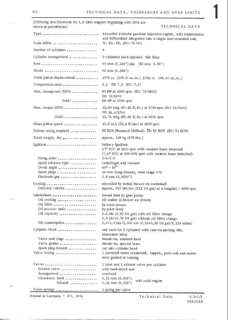
|
|
|
|
| bondo |
Apr 6 2005, 10:56 PM
Post
#7
|
|
Practicing my perpendicular parking Group: Members Posts: 4,277 Joined: 19-April 03 From: Los Osos, CA Member No.: 587 Region Association: Central California |
That's is the way I do it.. works great. There's a brief description of it at the end of the pelican tech article for adjusting valves, which is where I found it. It was second nature to me because I learned how to adjust valves on an MGB. What I like most about it is it doesn't matter what flywheel mark is where, which tdc mark is what, etc. Dizzy cap stays on, don't even have to look at the flywheel. It almost makes the job fun. (IMG:http://www.914world.com/bbs2/html/emoticons/smile.gif)
|
|
|
|
| tdgray |
Apr 7 2005, 06:13 AM
Post
#8
|
|
Thank God Nemo is not here to see this Group: Members Posts: 9,706 Joined: 5-August 03 From: Akron, OH Member No.: 984 Region Association: None |
Somebody throw this into classic please (IMG:http://www.914world.com/bbs2/html/emoticons/smile.gif)
|
|
|
|
| Joseph Mills |
Apr 8 2005, 12:22 PM
Post
#9
|
||
|
on a Sonoma diet now... Group: Members Posts: 1,482 Joined: 29-December 02 From: Oklahoma City, OK Member No.: 39 |
Excellent. Thanks Cap'n for the overview of the "why" and the indepth of the "how". I am now ready to do this. This definitely needs to be in our classics thread section. (IMG:http://www.914world.com/bbs2/html/emoticons/rolleyes.gif) |
||
|
|
|
||
| merrill |
Apr 8 2005, 01:05 PM
Post
#10
|
|
Dirt Pimp Group: Members Posts: 224 Joined: 25-January 05 From: Tahoe City, Ca Member No.: 3,505 Region Association: None |
(IMG:http://www.914world.com/bbs2/html/emoticons/huh.gif) I actually understood and learned something today (IMG:http://www.914world.com/bbs2/html/emoticons/wacko.gif)
|
|
|
|
| tat2dphreak |
Apr 8 2005, 01:21 PM
Post
#11
|
|
stoya, stoya, stoya Group: Benefactors Posts: 8,797 Joined: 6-June 03 From: Wylie, TX Member No.: 792 Region Association: Southwest Region |
ok, one more time for those of us that rode in on the short bus: on the left side of your table is the ones you refer to as "rocking", and you adjust the ones on the right...
now, does that mean that the "rocking" 2 on the left will be "loose" (like if you wiggle them they will tap against the valve? or will the 2 rocking valves be tight, opening the valve in the head? (IMG:http://www.914world.com/bbs2/html/emoticons/huh.gif) I've done the pelican way a few times now, this one sounds easier, but I am confused on this 1 point... |
|
|
|
| Grimstead |
Apr 8 2005, 01:30 PM
Post
#12
|
|
Cheaky Monkey Group: Members Posts: 835 Joined: 20-March 05 From: Corona, Ca Member No.: 3,789 Region Association: Southern California |
Crap! Now I have no excuse not to adjust them mymelf this weekend. (IMG:http://www.914world.com/bbs2/html/emoticons/mad.gif)
Thanks for the post, great job! (IMG:http://www.914world.com/bbs2/html/emoticons/clap.gif) (IMG:http://www.914world.com/bbs2/html/emoticons/mueba.gif) (IMG:http://www.914world.com/bbs2/html/emoticons/rocking nana.gif) (IMG:http://www.914world.com/bbs2/html/emoticons/mueba.gif) |
|
|
|
| Bruce Allert |
Apr 8 2005, 01:40 PM
Post
#13
|
|
Hellions asleep Group: Members Posts: 3,289 Joined: 19-March 03 From: Eagle Creek, Orygun Member No.: 441 Region Association: Pacific Northwest |
(unless I'm adjusting my valves wrong...) (IMG:http://www.914world.com/bbs2/html/emoticons/unsure.gif)
Why is this way better or easier than beginning with #1 @ TDC, adjust both valves then rotate tire backwards for #2 & so on? I never could understand the way as mentioned above. Totally confused me. If I could see it I'd be able to do it but just reading it gives me pictures in my mind that aren't.... (IMG:http://www.914world.com/bbs2/html/emoticons/wacko.gif) ...b |
|
|
|
| gklinger |
Apr 8 2005, 01:43 PM
Post
#14
|
||||
|
doh! Group: Members Posts: 316 Joined: 14-January 03 From: Tempe, AZ Member No.: 146 Region Association: Southwest Region |
|
||||
|
|
|
||||
| Cap'n Krusty |
Apr 8 2005, 02:44 PM
Post
#15
|
|
Cap'n Krusty Group: Members Posts: 10,794 Joined: 24-June 04 From: Santa Maria, CA Member No.: 2,246 Region Association: Central California |
Some notes:
Sodium filled exhaust valves were available for 1.8s for a long time, and you would use the .008" figure for engines so equipped. However, Jim's figure was essentially wrong, and I missed it. Sorry. I will correct that in the final draft before (if) this thing goes to a permanent file somewhere. By "rocking", we mean having the pushrod in the fully extended position, and the "rocked" valve being fully open. It is at that point in the rotation of the camshaft that the valve directly opposite is at the lowest point on the base circle of the camshaft, and as closed as it is ever gonna get. That's where you want it to be for the most accurate valve adjustment. The Cap'n |
|
|
|
| Part Pricer |
Apr 11 2005, 02:43 PM
Post
#16
|
||||||||||
|
Believe everything I post Group: Benefactors Posts: 1,825 Joined: 28-December 02 From: Danbury, CT Member No.: 35 |
I just got done adjusting my valves using this method. It made things very easy.
However, it took me a few minutes of reading and re-reading the procedure until I realized what I needed to do. I know I'm thick, but my confusion could have been avoided with a little formatting. This made things much clearer for me:
|
||||||||||
|
|
|
||||||||||
| redshift |
Apr 11 2005, 02:46 PM
Post
#17
|
|
Bless the Hell out of you! Group: Members Posts: 10,926 Joined: 29-June 03 Member No.: 869 |
I am confused.
Is there an oil additive that does all this? M |
|
|
|
| Brando |
Apr 11 2005, 04:07 PM
Post
#18
|
|
BUY MY SPARE KIDNEY!!! Group: Members Posts: 3,935 Joined: 29-August 04 From: Santa Ana, CA Member No.: 2,648 Region Association: Southern California |
Well, I've attempted this method today.
Seems with the rear wheels off the ground it won't turn the engine over putting it in 4th or 5th. Or any gear for that matter. |
|
|
|
| Dave_Darling |
Apr 11 2005, 05:46 PM
Post
#19
|
|
914 Idiot Group: Members Posts: 15,356 Joined: 9-January 03 From: Silicon Valley / Kailua-Kona Member No.: 121 Region Association: Northern California |
One rear wheel--only one rear wheel should be off the ground. If both are, your open differential just spins the other rear wheel the opposite way.
Or you may be able to find a way to block one rear wheel from turning. Or you might rotate the engine by turning the fan somehow. (If you do, pull the spark plugs so the engine spins more easily!) Or by pusing the car back and forth in gear. Or by bumping the starter repeatedly. Or.... --DD |
|
|
|
| Joseph Mills |
Apr 11 2005, 07:53 PM
Post
#20
|
||
|
on a Sonoma diet now... Group: Members Posts: 1,482 Joined: 29-December 02 From: Oklahoma City, OK Member No.: 39 |
Did you try some of Redshift's special oil additive first?? (IMG:http://www.914world.com/bbs2/html/emoticons/biggrin.gif) Just wedge a wood block in one of the wheels so it won't turn. Or use your floor jack under one of the wheels - lift it up an inch or so where it won't turn. Don't tip your car over. (IMG:http://www.914world.com/bbs2/html/emoticons/biggrin.gif) Now when you turn the other wheel (5th gear), you will spin the engine, or rock it back and forth. Gives you a lot of control and works real well. |
||
|
|
|
||
|
2 User(s) are reading this topic (2 Guests and 0 Anonymous Users)
0 Members:

|
Lo-Fi Version | Time is now: 28th July 2026 - 06:28 PM |
Invision Power Board
v9.1.4 © 2026 IPS, Inc.