|
|
|
Porsche, and the Porsche crest are registered trademarks of Dr. Ing. h.c. F. Porsche AG.
This site is not affiliated with Porsche in any way. Its only purpose is to provide an online forum for car enthusiasts. All other trademarks are property of their respective owners. |
|
|

  |

| Howie149 |
 Aug 10 2016, 08:42 PM Aug 10 2016, 08:42 PM
Post
#1
|
|
Newbie  Group: Members Posts: 4 Joined: 10-August 16 From: Emerald Hills, CA Member No.: 20,286 Region Association: None |
I have a 1970 914/6. When I pulled the motor out, the 14 pin Main Harness that sits on the Relay Board in the engine compartment came apart. Thus I have no idea which wire goes where. I have 6 wires. (2 are grey and black and go to the transmission back-up switch/sender. 1 Green and brown and 1 Green and black go to the oil pressure and oil level senders. 1 Black and red goes to the coil and I'm not sure about the black and blue/purple.) I have attached a picture of the harness below.
I would enjoy any guidance on where to plug these wires. Car won't start and it keeps blowing fuses which I assume is either a problem with these wires or the ignition system/distributor needs an overhaul. Attached thumbnail(s) 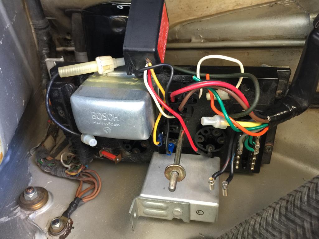
|
   |

 
|
| cary |
Aug 10 2016, 09:06 PM
Post
#2
|
|
Advanced Member Group: Members Posts: 3,900 Joined: 26-January 04 From: Sherwood Oregon Member No.: 1,608 Region Association: Pacific Northwest |
Your fired ...
You need to give the car to me .... LOL All kidding aside. No big deal. If you look closely at the black connector it should have little numbers. The schematic will have matching numbers. Just plug them back in the correct hole. I'm stripping down another 964 at work. While removing the 40# harness. One of the 6 pin versions behind the gauges came apart. I got lucky. It didn't explode like yours. |
|
|
|
| Howie149 |
Aug 10 2016, 09:39 PM
Post
#3
|
|
Newbie Group: Members Posts: 4 Joined: 10-August 16 From: Emerald Hills, CA Member No.: 20,286 Region Association: None |
QUOTE(cary @ Aug 10 2016, 08:06 PM)  Your fired ... You need to give the car to me .... LOL All kidding aside. No big deal. If you look closely at the black connector it should have little numbers. The schematic will have matching numbers. Just plug them back in the correct hole. I'm stripping down another 964 at work. While removing the 40# harness. One of the 6 pin versions behind the gauges came apart. I got lucky. It didn't explode like yours. Yeah I saw the numbers. I wish it was that easy. I don't have a schematic for that part of the harness. I have the shop manuals for the 914 but not going back to 1970. The schematics are for other relay brackets and different main harnesses. Everything else is either too small to read, not in color or clearly wrong. |
|
|
|
| cary |
Aug 10 2016, 09:41 PM
Post
#4
|
|
Advanced Member Group: Members Posts: 3,900 Joined: 26-January 04 From: Sherwood Oregon Member No.: 1,608 Region Association: Pacific Northwest |
My manuals are at my shop.
I won't be out there till Friday. Hopefully someone will chime in with what you need before that. |
|
|
|
| porschetub |
Aug 10 2016, 10:45 PM
Post
#5
|
|
914 Guru Group: Members Posts: 5,081 Joined: 25-July 15 From: New Zealand Member No.: 18,995 Region Association: None |
[quote name='Howie149' post='2383480' date='Aug 11 2016, 03:39 PM']
[quote name='cary' post='2383467' date='Aug 10 2016, 08:06 PM'] Your fired ... You need to give the car to me .... LOL All kidding aside. No big deal. If you look closely at the black connector it should have little numbers. The schematic will have matching numbers. Just plug them back in the correct hole. I'm stripping down another 964 at work. While removing the 40# harness. One of the 6 pin versions behind the gauges came apart. I got lucky. It didn't explode like yours. [/quote] Yeah I saw the numbers. I wish it was that easy. I don't have a schematic for that part of the harness. I have the shop manuals for the 914 but not going back to 1970. The schematics are for other relay brackets and different main harnesses. Everything else is either too small to read, not in color or clearly wrong. I have a schematic but I just looked and its for a 4 to 6cyl conversion ,try a google search 914/6 relay pins or similar,think I saw one a while back. Please move the Ashlock tach adaptor behind the dash where it belongs,these units aren't waterproof.it will fizz in this wet area. I will go back thru my notes and see what I can find on my old laptop...if it still works (IMG:style_emoticons/default/confused24.gif) Will get back soon hopefully. EDIT,found this from this site AA conversion book; 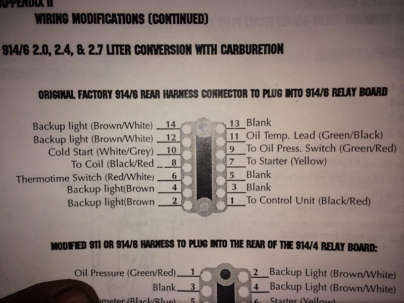 Hope it is some use. |
 |
|
| Peashooter |
Aug 11 2016, 05:42 AM
Post
#6
|
|
Member Group: Members Posts: 166 Joined: 17-December 11 From: SW Ohio Member No.: 13,903 Region Association: None |
QUOTE(Howie149 @ Aug 10 2016, 10:42 PM) I have a 1970 914/6. When I pulled the motor out, the 14 pin Main Harness that sits on the Relay Board in the engine compartment came apart. Thus I have no idea which wire goes where. I have 6 wires. (2 are grey and black and go to the transmission back-up switch/sender. 1 Green and brown and 1 Green and black go to the oil pressure and oil level senders. 1 Black and red goes to the coil and I'm not sure about the black and blue/purple.) I have attached a picture of the harness below. I would enjoy any guidance on where to plug these wires. Car won't start and it keeps blowing fuses which I assume is either a problem with these wires or the ignition system/distributor needs an overhaul. That is not a factory harness. Wire colors are totally different. Stock engine? |
|
|
|
| rgalla9146 |
Aug 11 2016, 08:05 AM
Post
#7
|
|
Advanced Member Group: Members Posts: 4,954 Joined: 23-November 05 From: Paramus NJ Member No.: 5,176 Region Association: None |
I took a picture of the multi-pin connectors with the caps removed but....you've got some non-original wires there.
Your car is an original 6 right ? Hope this helps Why do you have a tach adapter ? Attached thumbnail(s) 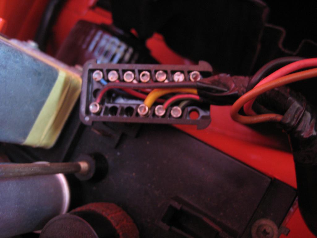 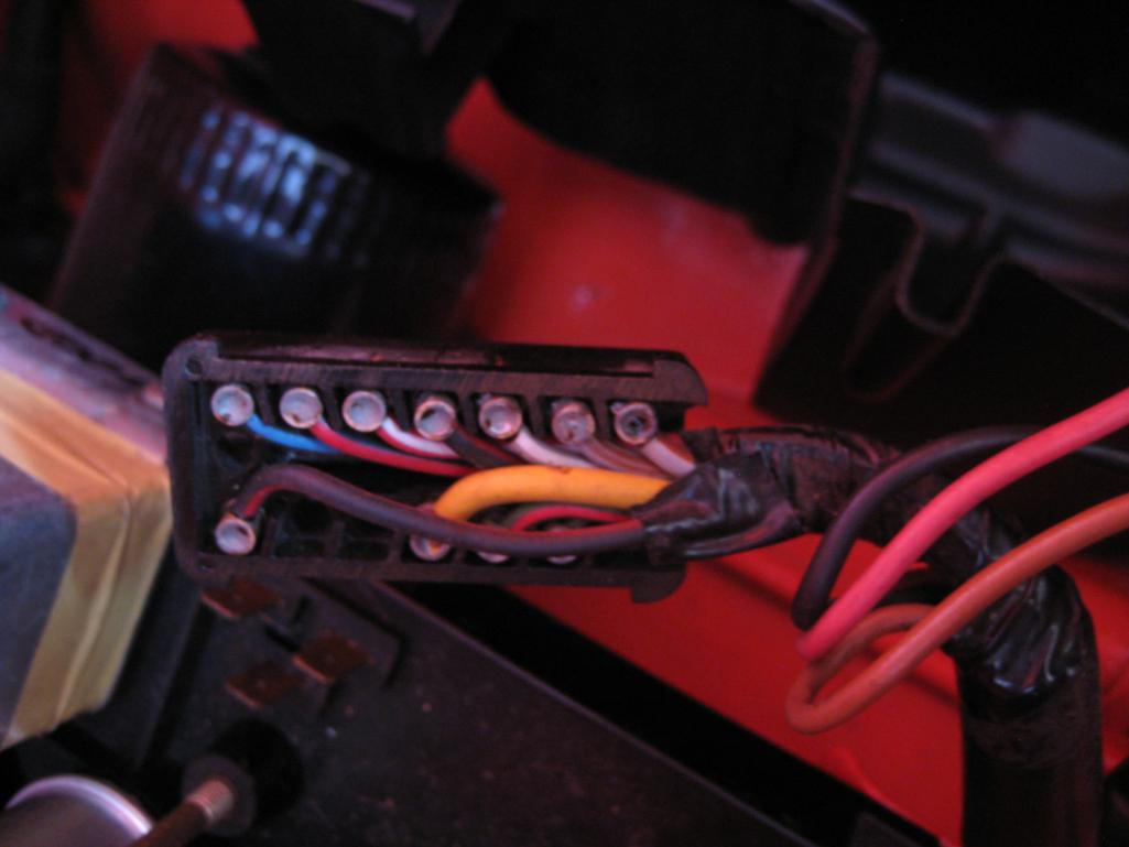
|
|
|
|
| JmuRiz |
Aug 11 2016, 08:24 AM
Post
#8
|
|
914 Guru Group: Members Posts: 5,625 Joined: 30-December 02 From: NoVA Member No.: 50 Region Association: MidAtlantic Region |
QUOTE(rgalla9146 @ Aug 11 2016, 06:05 AM) Why do you have a tach adapter ? I was thinking the same thing...if it's a real /6 there's no need. Maybe it's a conversion? |
|
|
|
| rgalla9146 |
Aug 11 2016, 10:39 AM
Post
#9
|
|
Advanced Member Group: Members Posts: 4,954 Joined: 23-November 05 From: Paramus NJ Member No.: 5,176 Region Association: None |
Most likely a real 6, the oil line to the tank has an aluminum collar. |
|
|
|
| Dion |
Aug 11 2016, 10:44 AM
Post
#10
|
|
RN Group: Members Posts: 2,926 Joined: 16-September 04 From: Audubon,PA Member No.: 2,766 Region Association: MidAtlantic Region |
QUOTE(JmuRiz @ Aug 11 2016, 06:24 AM) QUOTE(rgalla9146 @ Aug 11 2016, 06:05 AM) Why do you have a tach adapter ? I was thinking the same thing...if it's a real /6 there's no need. Maybe it's a conversion? I think I remember reading the tach adapt can also smooth out signals if the original tach is too bouncy. |
|
|
|
| Dave_Darling |
Aug 11 2016, 12:22 PM
Post
#11
|
|
914 Idiot Group: Members Posts: 15,338 Joined: 9-January 03 From: Silicon Valley / Kailua-Kona Member No.: 121 Region Association: Northern California |
If the wiring follows the same convention as the four-cylinder cars, the black/purple is the tach signal wire. It would likely have gone from the coil (-) terminal through the relay board to the tach.
--DD |
|
|
|
| porschetub |
Aug 11 2016, 01:12 PM
Post
#12
|
|
914 Guru Group: Members Posts: 5,081 Joined: 25-July 15 From: New Zealand Member No.: 18,995 Region Association: None |
QUOTE(Peashooter @ Aug 11 2016, 11:42 PM) QUOTE(Howie149 @ Aug 10 2016, 10:42 PM) I have a 1970 914/6. When I pulled the motor out, the 14 pin Main Harness that sits on the Relay Board in the engine compartment came apart. Thus I have no idea which wire goes where. I have 6 wires. (2 are grey and black and go to the transmission back-up switch/sender. 1 Green and brown and 1 Green and black go to the oil pressure and oil level senders. 1 Black and red goes to the coil and I'm not sure about the black and blue/purple.) I have attached a picture of the harness below. I would enjoy any guidance on where to plug these wires. Car won't start and it keeps blowing fuses which I assume is either a problem with these wires or the ignition system/distributor needs an overhaul. That is not a factory harness. Wire colors are totally different. Stock engine? Good spotting,no wire tracer colours,me thinks some time will be needed with a multimeter,expect the harness has been remade @ some stage ?, The other metal box plugged in to the relay board is a signal convertor for the tach right ? so as mentioned why the tach convertor. |
|
|
|
| Howie149 |
Aug 11 2016, 07:57 PM
Post
#13
|
|
Newbie Group: Members Posts: 4 Joined: 10-August 16 From: Emerald Hills, CA Member No.: 20,286 Region Association: None |
Its a numbers matching car but the wiring harness isn't stock. May be from a 914/4.
|
|
|
|
| Perry Kiehl Clone |
Aug 11 2016, 08:16 PM
Post
#14
|
|
Unregistered |
Looks like it could be one of my harnesses, or maybe a from a kit I sold. On a 914-6 the tach wire is black with a blue tracer. I've been swamped with a house project. I'll get the color coding and pin outs tomorrow. It really isn't hard to ohm out the wires and see where they are connected.
|
|
|
|
| ClayPerrine |
Aug 11 2016, 08:56 PM
Post
#15
|
|
Life's been good to me so far..... Group: Admin Posts: 16,542 Joined: 11-September 03 From: Hurst, TX. Member No.: 1,143 Region Association: NineFourteenerVille |
QUOTE(Dave_Darling @ Aug 11 2016, 01:22 PM) If the wiring follows the same convention as the four-cylinder cars, the black/purple is the tach signal wire. It would likely have gone from the coil (-) terminal through the relay board to the tach. --DD Actually Dave, on a six, it comes directly off the points. The negative coil terminal on a six is connected to ground. The positive comes from the CD box output. That's why they need a tach amplifier plugged into the relay board. This is the diagram of the ignition wiring from a early911/914-6. 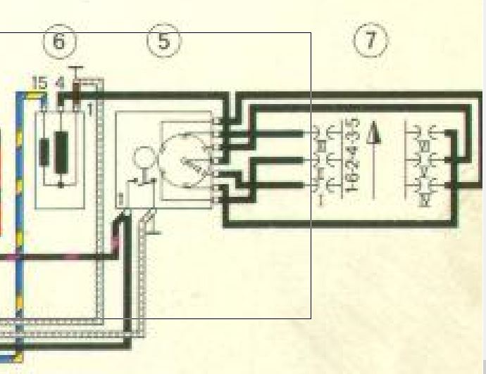 #6 is the coil. #5 is the distributor, and #7 is the engine. On the distributor, the black wire is the trigger to the CD box, the black/purple goes to the tach amplifier, and the white is actually a braided shield wire that is grounded on both ends. On the coil, the blue/yellow is the pulse out from the CD box. This is the CD box diagram. 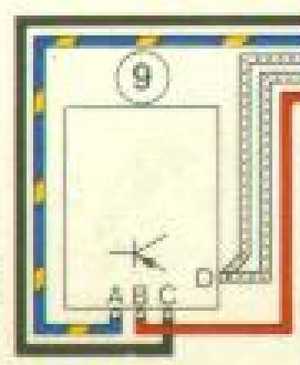 The only additional wire is the red switched ignition power wire. You still have the blue/yellow that goes to the positive side of the coil, the black wire which goes to the points, and the braided shield which goes to the negative side of the coil and also to ground. The Tach adapter on yours is wired to replace the tach amplifier that is NLA from Porsche. I had to do the same thing on my car. If you can find a factory tach amplifier, the early 911 concours guys will pay through the nose for them. I have a hand drawn pinout diagram, with proper wire color codes, for the six relay board in the garage. If you still need it tomorrow I can copy it and upload it. |
|
|
|
| sixnotfour |
Aug 11 2016, 09:25 PM
Post
#16
|
|
914 Wizard Group: Members Posts: 11,199 Joined: 12-September 04 Member No.: 2,744 Region Association: NineFourteenerVille |
Attached image(s) 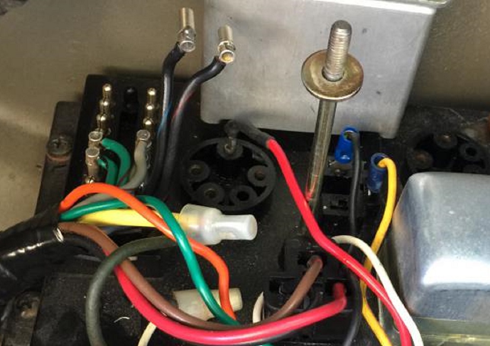
|
|
|
|
| porschetub |
Aug 11 2016, 10:24 PM
Post
#17
|
|
914 Guru Group: Members Posts: 5,081 Joined: 25-July 15 From: New Zealand Member No.: 18,995 Region Association: None |
QUOTE(Perry Kiehl Clone @ Aug 12 2016, 02:16 PM) Looks like it could be one of my harnesses, or maybe a from a kit I sold. On a 914-6 the tach wire is black with a blue tracer. I've been swamped with a house project. I'll get the color coding and pin outs tomorrow. It really isn't hard to ohm out the wires and see where they are connected. Nice to see someone step in with the knowledge that I most likely don't have....then what do I do .....I get Perry to build a loom for my conversion makes sense to me as I don't have the time also. I still think its important to have the tach adapt out of the engine bay,i mounted mine behind the gauges...could be wrong however. |
|
|
|
| Howie149 |
Aug 12 2016, 12:14 AM
Post
#18
|
|
Newbie Group: Members Posts: 4 Joined: 10-August 16 From: Emerald Hills, CA Member No.: 20,286 Region Association: None |
QUOTE(Perry Kiehl Clone @ Aug 11 2016, 07:16 PM) Looks like it could be one of my harnesses, or maybe a from a kit I sold. On a 914-6 the tach wire is black with a blue tracer. I've been swamped with a house project. I'll get the color coding and pin outs tomorrow. It really isn't hard to ohm out the wires and see where they are connected. Thanks very much. I'm not at all good with electrical issues. No idea what ohming out the wires means. But any guidance is great. It may end up that I need a proper harness for the back. I think it is the original board...just an odd wiring job. |
|
|
|
| SixerJ |
Aug 12 2016, 12:43 AM
Post
#19
|
|
Member Group: Members Posts: 451 Joined: 24-June 13 From: UK Member No.: 16,042 Region Association: England |
Positive you have a six board, two vertical plugs as opposed to one vertical and one horizontal for a 4
Ohming out just means a continuity test pin to pin between the various component on the diagram to identify which wire colour goes from pin x on the exploded plug to say pin y on the distributor, CDI box etc If you don't have a auto specific multimeter (going to be useful in your Porsche journey) even a bog basic multimeter from you local diy store or Amazon will do Dial into ohms (upside down U) and start buzzing wires out I would also try and get the tach adapter apart to replace the frayed yellow wire. I almost lost my 911 to mr smokey because of a frayed wire like that. Lots of frantic pulling wires out from the dash light switch. Very scary and a few very warm fingers Don't think I have a diagram, will check on Dropbox (edit. Just checked, nope don't have the electrical section of the workshop manual / diagram) Good luck |
|
|
|
|
1 User(s) are reading this topic (1 Guests and 0 Anonymous Users)
0 Members:

|
Lo-Fi Version | Time is now: 16th April 2026 - 07:26 PM |
Invision Power Board
v9.1.4 © 2026 IPS, Inc.