|
|
|
Porsche, and the Porsche crest are registered trademarks of Dr. Ing. h.c. F. Porsche AG.
This site is not affiliated with Porsche in any way. Its only purpose is to provide an online forum for car enthusiasts. All other trademarks are property of their respective owners. |
|
|

  |

| Mblizzard |
 Oct 17 2016, 04:13 PM Oct 17 2016, 04:13 PM
Post
#141
|
|
Advanced Member  Group: Members Posts: 3,033 Joined: 28-January 13 From: Knoxville Tn Member No.: 15,438 Region Association: South East States |
QUOTE(cgnj @ Oct 17 2016, 01:39 PM)  QUOTE(Mark Henry @ Oct 13 2016, 09:31 PM) I confirmed that you can't use 36-1 crank wheel mounted behind the fan with a stock AC pulley. Have you decided what to do about this issue? Thanks for the confirmation. It seemed that way. Not sure where to go. The dizzy should be the best option but I have to work it out a bit more. Need to get the fuel part sorted first. |
   |

 
|
| crash914 |
Oct 17 2016, 05:19 PM
Post
#142
|
|
its a mystery to me Group: Members Posts: 1,826 Joined: 17-March 03 From: Marriottsville, MD Member No.: 434 Region Association: MidAtlantic Region |
Damn, I was in Anacortes last Tuesday/Wednesday! would have bought you a beer..
QUOTE(aircooledtechguy @ Oct 13 2016, 02:07 PM) QUOTE(McMark @ Oct 13 2016, 06:31 AM) QUOTE(aircooledtechguy @ Oct 12 2016, 06:13 PM) As far as impedance goes, this is why everyone should consider ditching Microsquirt as a plan and step up to either MS3 or one of ECUs from thedubshop.net (I'm talking the one that Mario recently began offering). MicroS is NOT able to be modified, so you're stuck with whatever they offered it with 7-8 years ago or more. Time had marched on and high impedance injectors are the way to go for most, but if you want to run your old injectors, this leaves you having to re-invent the wheel. WHAT!??!? (IMG:style_emoticons/default/blink.gif) Everyone should ditch MicroSquirt so they can run stock low-impedance injectors? This is advice? (IMG:style_emoticons/default/WTF.gif) MicroSquirt has SO MANY advantages in terms of simplicity for people who just want a simple D-Jet replacement. If you can't see those advantages, you're keeping yourself intentionally blind. Yes, an MS3 has way more advanced features than MicroSquirt. But as you said, "It's really easy to get lost in all the obscure details and overthink this stuff, making it over-complicated." So it seems to me that a small, weatherproof and fully functional ECU would be a step toward simplicity. You're pontificating on the benefits of MS3 because it can be modified and in the next breath promoting simplicity. Those are diametrically opposite. You can't promote both. YOU are letting your DubShop promotion job get in the way of actually helping people. I have firsthand experience. MicroSquirt works. It does everything most people need for half the price. Please, take the challenge and explain to me how a normally aspirated 2056 needs a fucking MS3! I was not clear in my response; sorry. The above response was actually meant for those who have yet to purchase an ECU. You can order it from wherever you buy it with the features you want so there's no need to mod it yourself. The main advantage to MS3 is the resolution in tuning over any of the previous versions. Everything is pretty much built in already so the user just uses what they want and not what they don't. MS3 for a 2056 is likely more than what most would need, however how many people stay with a 2056 over the life of their cars?? Many people I know tend to want to step up to a larger motor later on. That's where a system capable of more things like sequential fuel & spark become rather important. I run my system on a small street motor and on my race motor. Yes I don't need sequential fuel & spark on a 2056 with the cam that has, but it is important on the other motor I run in this car with the exact same system. Over the last 5-7 years I have watched and read many threads from folks on this board who have problems getting their Microsquirt systems driving on the street and performing like they should. It's a perfectly capable system, but there are a lot less users of it and therefore less of a pool of knowledgeable people with successful conversions with which to draw experience from when problems arise. That's just not the case with MS2 or MS3. Say what you will about myself being a "shill" for my friend. I really don't care what you all say about that. His systems/products work and work well and his after sale support is second to none, no matter who you are or where you live. Why would I not mention ANYONE with that reputation?? I don't give anyone any crap about pimping your services. Should I be?? (IMG:style_emoticons/default/confused24.gif) (IMG:style_emoticons/default/rolleyes.gif) |
|
|
|
| McMark |
Oct 17 2016, 05:52 PM
Post
#143
|
|
914 Freak! Group: Retired Admin Posts: 20,179 Joined: 13-March 03 From: Grand Rapids, MI Member No.: 419 Region Association: None |
QUOTE(Mblizzard @ Oct 17 2016, 06:13 PM) Thanks for the confirmation. It seemed that way. Not sure where to go. The dizzy should be the best option but I have to work it out a bit more. I have an AC pulley with magnets in it for a hall pickup. You could use this setup. Not as accurate as a VR sensor, but it works. It's what SDS uses on their setup. I build this pickup mount for an SDS install. Attached image(s) 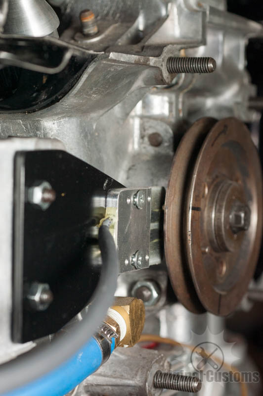
|
|
|
|
| Mblizzard |
Oct 18 2016, 06:21 AM
Post
#144
|
|
Advanced Member Group: Members Posts: 3,033 Joined: 28-January 13 From: Knoxville Tn Member No.: 15,438 Region Association: South East States |
QUOTE(McMark @ Oct 17 2016, 03:52 PM) QUOTE(Mblizzard @ Oct 17 2016, 06:13 PM) Thanks for the confirmation. It seemed that way. Not sure where to go. The dizzy should be the best option but I have to work it out a bit more. I have an AC pulley with magnets in it for a hall pickup. You could use this setup. Not as accurate as a VR sensor, but it works. It's what SDS uses on their setup. I build this pickup mount for an SDS install. I like that. Ok to be clear, I have learned just enough about all of this to be really dangerous so bear with me! Would it not be just as easy to install something like this on the impeller? |
|
|
|
| McMark |
Oct 18 2016, 07:06 AM
Post
#145
|
|
914 Freak! Group: Retired Admin Posts: 20,179 Joined: 13-March 03 From: Grand Rapids, MI Member No.: 419 Region Association: None |
You could do that. (IMG:style_emoticons/default/thumb3d.gif)
|
|
|
|
| Mark Henry |
Oct 18 2016, 07:57 AM
Post
#146
|
|
that's what I do! Group: Members Posts: 20,065 Joined: 27-December 02 From: Port Hope, Ontario Member No.: 26 Region Association: Canada |
Impeller would be a PITA because you have to be able to set the gap between the sensor and magnets.
My first SDS I just drew up some circles on sheet of aluminum, cut it out with a jigsaw, drilled it to bolt to the stock fan spacer washer. The sensor just bolted to the fan housing with a small mount I made. Here's the link to my first install and it shows how I did the crank mount. Yes I have been running programmable FI for a long time, longer than anyone on this board. http://www.914world.com/bbs2/index.php?act...;f=2&t=5396 (IMG:http://www.914world.com/bbs2/uploads/post-2-1065147062.jpg) |
|
|
|
| Mblizzard |
Oct 18 2016, 08:21 AM
Post
#147
|
|
Advanced Member Group: Members Posts: 3,033 Joined: 28-January 13 From: Knoxville Tn Member No.: 15,438 Region Association: South East States |
QUOTE(Mark Henry @ Oct 18 2016, 05:57 AM) Impeller would be a PITA because you have to be able to set the gap between the sensor and magnets. My first SDS I just drew up some circles on sheet of aluminum, cut it out with a jigsaw, drilled it to bolt to the stock fan spacer washer. The sensor just bolted to the fan housing with a small mount I made. Here's the link to my first install and it shows how I did the crank mount. Yes I have been running programmable FI for a long time, longer than anyone on this board. http://www.914world.com/bbs2/index.php?act...;f=2&t=5396 (IMG:http://www.914world.com/bbs2/uploads/post-2-1065147062.jpg) I would think with the hole in the top of the impeller housing it would be easy to thread in the sensor and set it at the correct distance. Pretty much not going to need to set the timing from there after the install. But I am just sitting here thinking not actually doing. |
|
|
|
| Mark Henry |
Oct 18 2016, 01:58 PM
Post
#148
|
|
that's what I do! Group: Members Posts: 20,065 Joined: 27-December 02 From: Port Hope, Ontario Member No.: 26 Region Association: Canada |
QUOTE(Mblizzard @ Oct 18 2016, 10:21 AM) I would think with the hole in the top of the impeller housing it would be easy to thread in the sensor and set it at the correct distance. Pretty much not going to need to set the timing from there after the install. But I am just sitting here thinking not actually doing. I just mounted the fan shroud and checked the gap. Gap is not super critical, it's something like .025 to .060", the big one is you never want the magnets to hit the sensor. Once you are happy you red locktite all the screws (blue on the adjuster screws), install the fan and button it up. You should never have to adjust it again. It took some time but it wasn't that hard to do. If I could find the mount I'd send it to you, but I changed it out several years ago. |
|
|
|
| N_Jay |
Oct 18 2016, 02:27 PM
Post
#149
|
|
Member Group: Members Posts: 283 Joined: 2-March 16 From: Chicago NW Burbs Member No.: 19,720 Region Association: None |
QUOTE(Mblizzard @ Oct 18 2016, 09:21 AM) I would think with the hole in the top of the impeller housing it would be easy to thread in the sensor and set it at the correct distance. Pretty much not going to need to set the timing from there after the install. But I am just sitting here thinking not actually doing. That was my first thought. Looked like a easy win. Guessing other know better. |
|
|
|
| Mark Henry |
Oct 18 2016, 03:21 PM
Post
#150
|
|
that's what I do! Group: Members Posts: 20,065 Joined: 27-December 02 From: Port Hope, Ontario Member No.: 26 Region Association: Canada |
QUOTE(N_Jay @ Oct 18 2016, 04:27 PM) QUOTE(Mblizzard @ Oct 18 2016, 09:21 AM) I would think with the hole in the top of the impeller housing it would be easy to thread in the sensor and set it at the correct distance. Pretty much not going to need to set the timing from there after the install. But I am just sitting here thinking not actually doing. That was my first thought. Looked like a easy win. Guessing other know better. Nope...you need the timing hole, you have to set the initial timing with a strobe. The ecu is good, but it can't guess where the timing is set the first time. Once you enter/adjust the timing value, so that both the ECU and strobe is seeing say 10 degrees BTDC idle at the same time, then you never have to break out the strobe again. |
|
|
|
| Mblizzard |
Oct 23 2016, 05:38 PM
Post
#151
|
|
Advanced Member Group: Members Posts: 3,033 Joined: 28-January 13 From: Knoxville Tn Member No.: 15,438 Region Association: South East States |
Well some minor progress was made.
Finished the TPS wiring. 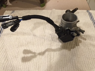 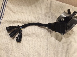 Came up with a pretty cool way to install the air temp sensor using the cold start valve. 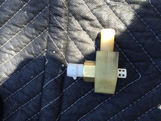 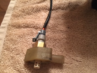 And made the injector harness. 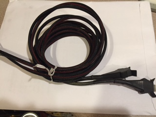 And made the resistor pack for the injectors. 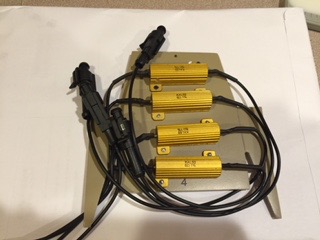 Attached image(s) 
|
|
|
|
| Mblizzard |
Oct 31 2016, 09:06 AM
Post
#152
|
|
Advanced Member Group: Members Posts: 3,033 Joined: 28-January 13 From: Knoxville Tn Member No.: 15,438 Region Association: South East States |
I was a complete slacker this weekend! Weather was great and my wife said lets enjoy the weekend together so I got nothing done!
Heading to Ukraine next weekend so the progress will be slowed considerable. |
|
|
|
| McMark |
Nov 16 2016, 01:04 PM
Post
#153
|
|
914 Freak! Group: Retired Admin Posts: 20,179 Joined: 13-March 03 From: Grand Rapids, MI Member No.: 419 Region Association: None |
QUOTE(Mblizzard @ Oct 17 2016, 09:15 AM) QUOTE(McMark @ Oct 16 2016, 07:36 PM) My wiring harness connects to and uses the stock relay panel. It's got the two relays you need and access to them via the four pin FI connection. You can use standard spade connections, or the stock style four pin connector is available. I like your mounting board though. Looks like you got it sorted out, but I forgot to mention the TPS can be spaced off the adapter plate (which is looks like you did), or you can trim the throttle shaft so everything sits flush. McMark as others might want to look at a premade arrangement for the harness, could you post a picture of yours? Found a picture Zach took of my harness and remembered this thread. (IMG:http://www.914world.com/bbs2/uploads/post-8858-1432865334.jpg) |
|
|
|
| Montreal914 |
Feb 5 2017, 11:03 PM
Post
#154
|
|
Senior Member Group: Members Posts: 1,552 Joined: 8-August 10 From: Claremont, CA Member No.: 12,023 Region Association: Southern California |
This was an interesting thread, any progress? (IMG:style_emoticons/default/smile.gif) Thank you.
(IMG:style_emoticons/default/chowtime.gif) (IMG:style_emoticons/default/popcorn[1].gif) |
 |
|
| Mblizzard |
Feb 6 2017, 07:36 PM
Post
#155
|
|
Advanced Member Group: Members Posts: 3,033 Joined: 28-January 13 From: Knoxville Tn Member No.: 15,438 Region Association: South East States |
A bit stalled due to time and work crunches. But will be turning back to it soon.
|
|
|
|
| Mblizzard |
May 7 2017, 05:05 PM
Post
#156
|
|
Advanced Member Group: Members Posts: 3,033 Joined: 28-January 13 From: Knoxville Tn Member No.: 15,438 Region Association: South East States |
Ok so a few things have moved on so i am now returning to this!
Seems like I have all of my parts now as i just picked up a Idle Air control valve. After rethinking a few things i decided to get rid of the low impeadance injectors and buy new high impeadance ones. Kind of blows my low dollar approach but it seems that if i was really going for a modern system then i might as well go all in. Gone through some bench testing of the components and it seems like everything is measuring as it should. Temp gauges, TPS, MAP all seem to be working. Wish I could easily use a sequential injector fire approach but seems like i will be using batch fire. Maybe with the modern feed back controls it wont be an issue. Should have a free weekend next week and start the swap then. As a question what is the best way to deal with the wires that are not being used for a fuel only appliacation? |
|
|
|
| McMark |
May 8 2017, 05:40 AM
Post
#157
|
|
914 Freak! Group: Retired Admin Posts: 20,179 Joined: 13-March 03 From: Grand Rapids, MI Member No.: 419 Region Association: None |
You'll never notice the difference between sequential injection an batch injection.
QUOTE As a question what is the best way to deal with the wires that are not being used for a fuel only appliacation? I'd remove them at the main connector. But if you're gonna leave them, get some small heat shrink and put a little section off the end of each wire (half on, half off, then shrink). Then use large heat shink to collect unused wires into a bundle. |
|
|
|
| Mblizzard |
May 8 2017, 01:24 PM
Post
#158
|
|
Advanced Member Group: Members Posts: 3,033 Joined: 28-January 13 From: Knoxville Tn Member No.: 15,438 Region Association: South East States |
I am sure there are other places to get the high impedance injectors that will work with the stock injector hold downs but I happened to find them here if anyone else is looking for them.
|
|
|
|
| Mblizzard |
May 9 2017, 06:13 PM
Post
#159
|
|
Advanced Member Group: Members Posts: 3,033 Joined: 28-January 13 From: Knoxville Tn Member No.: 15,438 Region Association: South East States |
QUOTE(McMark @ May 8 2017, 03:40 AM) You'll never notice the difference between sequential injection an batch injection. QUOTE As a question what is the best way to deal with the wires that are not being used for a fuel only appliacation? I'd remove them at the main connector. But if you're gonna leave them, get some small heat shrink and put a little section off the end of each wire (half on, half off, then shrink). Then use large heat shink to collect unused wires into a bundle.At the risk of proving to the world just how big an idiot i am, what is the process for removing wires from the harness? |
|
|
|
| VaccaRabite |
May 9 2017, 07:14 PM
Post
#160
|
|
En Garde! Group: Admin Posts: 13,442 Joined: 15-December 03 From: Dallastown, PA Member No.: 1,435 Region Association: MidAtlantic Region |
QUOTE(Mblizzard @ May 9 2017, 08:13 PM) QUOTE(McMark @ May 8 2017, 03:40 AM) You'll never notice the difference between sequential injection an batch injection. QUOTE As a question what is the best way to deal with the wires that are not being used for a fuel only appliacation? I'd remove them at the main connector. But if you're gonna leave them, get some small heat shrink and put a little section off the end of each wire (half on, half off, then shrink). Then use large heat shink to collect unused wires into a bundle.At the risk of proving to the world just how big an idiot i am, what is the process for removing wires from the harness? gently cut off the shrink wrap around the wire harness. isolate the wires that you want to remove. the AmpSeal block unlocks at the front and rear. do some you tube research on how to seat and unseat wires in the Ampseal. It is easy to break the block at the locking tabs. Pull the wires out of the Ampseal. Rewrap the harness in heat shrink tube or wire harness wrap. Zach |
|
|
|
|
1 User(s) are reading this topic (1 Guests and 0 Anonymous Users)
0 Members:

|
Lo-Fi Version | Time is now: 12th May 2024 - 03:47 PM |
Invision Power Board
v9.1.4 © 2024 IPS, Inc.