|
|
|
Porsche, and the Porsche crest are registered trademarks of Dr. Ing. h.c. F. Porsche AG.
This site is not affiliated with Porsche in any way. Its only purpose is to provide an online forum for car enthusiasts. All other trademarks are property of their respective owners. |
|
|

  |

| McMark |
 May 30 2017, 09:41 AM May 30 2017, 09:41 AM
Post
#201
|
|
914 Freak!  Group: Retired Admin Posts: 20,179 Joined: 13-March 03 From: Grand Rapids, MI Member No.: 419 Region Association: None |
Yeah, you're right. If you were trying to count 4-trigger events, it would be 1/4 speed. But really you just care about 1 single TDC marker. You could get a bare hall effect sensor and mount that on one side of the trigger point plate. It would take some trial and error, but it should be doable. The cam for the trigger points (on the dist. shaft) is not the ideal shape because the ramps are smooth.
Attached image(s) 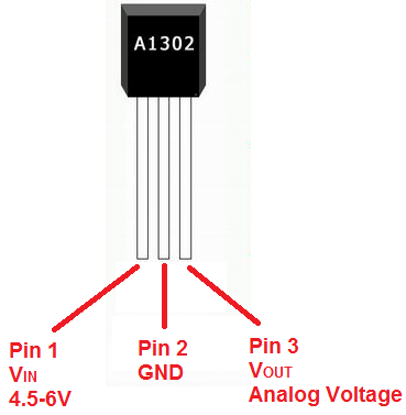
|
   |

 
|
| McMark |
May 30 2017, 09:44 AM
Post
#202
|
|
914 Freak! Group: Retired Admin Posts: 20,179 Joined: 13-March 03 From: Grand Rapids, MI Member No.: 419 Region Association: None |
Actually, you may be able to trigger it off on one side of the trigger points.
|
|
|
|
| timothy_nd28 |
May 30 2017, 10:27 AM
Post
#203
|
|
Advanced Member Group: Members Posts: 2,299 Joined: 25-September 07 From: IN Member No.: 8,154 Region Association: Upper MidWest |
I'm not familiar with the 123 distributor or the megasquirt setup so I can be totally wrong with any advice. It's possible that the your microsquirt isn't hearing the signal from your dizzy. You could try a 10k ohm pull up resistor to see if that helps.
|
|
|
|
| Mblizzard |
May 30 2017, 12:07 PM
Post
#204
|
|
Advanced Member Group: Members Posts: 3,033 Joined: 28-January 13 From: Knoxville Tn Member No.: 15,438 Region Association: South East States |
In which configuration are you talking about? Firing from the coil or the trigger points? Attached is some info I have on dizzy.
 123PORSCHE4.pdf ( 317.59k )
Number of downloads: 54
123PORSCHE4.pdf ( 317.59k )
Number of downloads: 54It is clear that the signal I get off the trigger point is very noisy and the rpm are erratic. I tried a variable resistor to 5K with no noticeable difference. Got some resistors coming to try other values. I think I found a way in the software to tell the ECU more about the system. Going to see if it will allow the a Non missing tooth on cam set up with a Single tooth on crank or two opposite teeth on cam the 2 opposite teeth should mimic the trigger points pretty well. 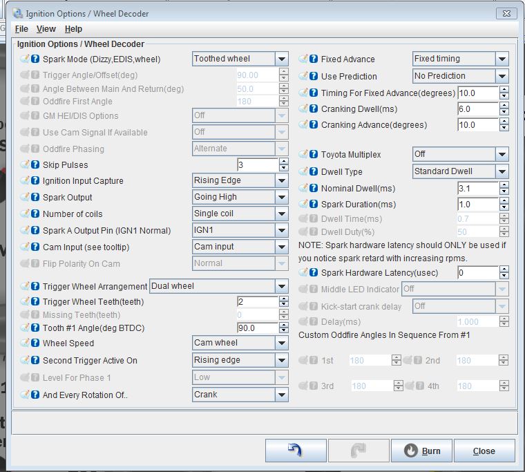 Attached File(s)
123PORSCHE4.pdf ( 317.59k )
Number of downloads: 78 |
|
|
|
| timothy_nd28 |
May 30 2017, 12:20 PM
Post
#205
|
|
Advanced Member Group: Members Posts: 2,299 Joined: 25-September 07 From: IN Member No.: 8,154 Region Association: Upper MidWest |
Trigger points
|
|
|
|
| Mblizzard |
May 30 2017, 01:05 PM
Post
#206
|
|
Advanced Member Group: Members Posts: 3,033 Joined: 28-January 13 From: Knoxville Tn Member No.: 15,438 Region Association: South East States |
QUOTE(timothy_nd28 @ May 30 2017, 10:20 AM)  Trigger points Did try the variable resistor but only went to 5K. Also not sure if this should be pull up or pull down. |
|
|
|
| Mblizzard |
May 30 2017, 01:07 PM
Post
#207
|
|
Advanced Member Group: Members Posts: 3,033 Joined: 28-January 13 From: Knoxville Tn Member No.: 15,438 Region Association: South East States |
QUOTE(McMark @ May 30 2017, 07:41 AM) Yeah, you're right. If you were trying to count 4-trigger events, it would be 1/4 speed. But really you just care about 1 single TDC marker. You could get a bare hall effect sensor and mount that on one side of the trigger point plate. It would take some trial and error, but it should be doable. The cam for the trigger points (on the dist. shaft) is not the ideal shape because the ramps are smooth. No cam in the dizzy. Trigger points replaced with electronic out put. I think I am getting the analog voltage out signal from the trigger points but I am not sure how to tell the EWCU what it is seeing. |
|
|
|
| timothy_nd28 |
May 30 2017, 02:25 PM
Post
#208
|
|
Advanced Member Group: Members Posts: 2,299 Joined: 25-September 07 From: IN Member No.: 8,154 Region Association: Upper MidWest |
Looks like this 123 dizzy is a drop in replacement for the Djet as it has 2 wires for the fuel trigger points. The two wires seem to go to each fuel injector bank respectively at the ECU. The manual says to connect to pins 1 and 3 at the bosch FI trigger connector, since it's missing the third wire, I assume that this module is supplying its own ground.
With the above said, I'm assuming that this dizzy has an internal optoisolator that is triggering a switch which is independent from the rest of the ignition. I think these two wires are pulling to ground in a wig wag pattern because the OEM setup had 2 cam lobes that would fire a set of injectors independently from each other. If you wired these two wires coming from the dizzy together as part of the whole circuit, the circuit would never complete because one contact would pull to ground as the other contact would open to infinity, thus a open circuit that the microsquirt would never see. On a napkin, draw a sketch on how you had this wired previously. This is a good break from the biochem studying (IMG:style_emoticons/default/biggrin.gif) |
|
|
|
| McMark |
May 30 2017, 02:44 PM
Post
#209
|
|
914 Freak! Group: Retired Admin Posts: 20,179 Joined: 13-March 03 From: Grand Rapids, MI Member No.: 419 Region Association: None |
Yeah, that's MS2Extra Firmware.
Another point on the MS learning curve. Each firmware makes TunerStudio look completely different. So unless you're running the same firmware, comparing notes is useless. I haven't played with MS2E much, so I'm not familiar with all the settings. |
|
|
|
| Mblizzard |
May 30 2017, 02:56 PM
Post
#210
|
|
Advanced Member Group: Members Posts: 3,033 Joined: 28-January 13 From: Knoxville Tn Member No.: 15,438 Region Association: South East States |
QUOTE(timothy_nd28 @ May 30 2017, 12:25 PM) Looks like this 123 dizzy is a drop in replacement for the Djet as it has 2 wires for the fuel trigger points. The two wires seem to go to each fuel injector bank respectively at the ECU. The manual says to connect to pins 1 and 3 at the bosch FI trigger connector, since it's missing the third wire, I assume that this module is supplying its own ground. With the above said, I'm assuming that this dizzy has an internal optoisolator that is triggering a switch which is independent from the rest of the ignition. I think these two wires are pulling to ground in a wig wag pattern because the OEM setup had 2 cam lobes that would fire a set of injectors independently from each other. If you wired these two wires coming from the dizzy together as part of the whole circuit, the circuit would never complete because one contact would pull to ground as the other contact would open to infinity, thus a open circuit that the microsquirt would never see. On a napkin, draw a sketch on how you had this wired previously. This is a good break from the biochem studying (IMG:style_emoticons/default/biggrin.gif) Yep nothing more boring than double-reciprocal plots (Lineweaver-Burk) for enzyme kinetics. As you noted there is only one out wire from the Dizzy. I assumed the power coming in was the 12V being supplied to the dizzy from the + side of coil. So I put in the initial 1K pull up as shown with out any impact and it did not change going to 5K. 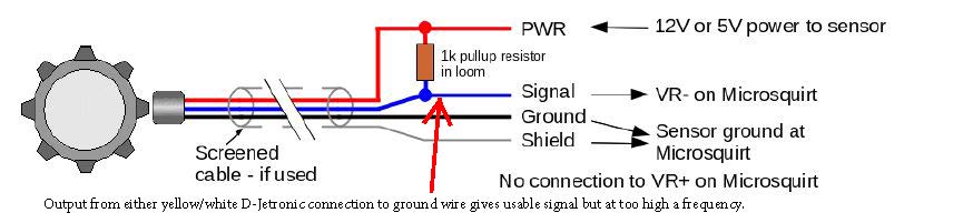 The ground shown in the figure is not there from the dizzy. The ECU wants all of the sensors to use a common sensor ground which is isolated from the other common ground to reduce noise. No way to tap that so this circuit is bound to have some noise. The attached graph shows the RPM going from 3K to 0 in just few ms. The dash showed only about 1.5K so it seems doubled. 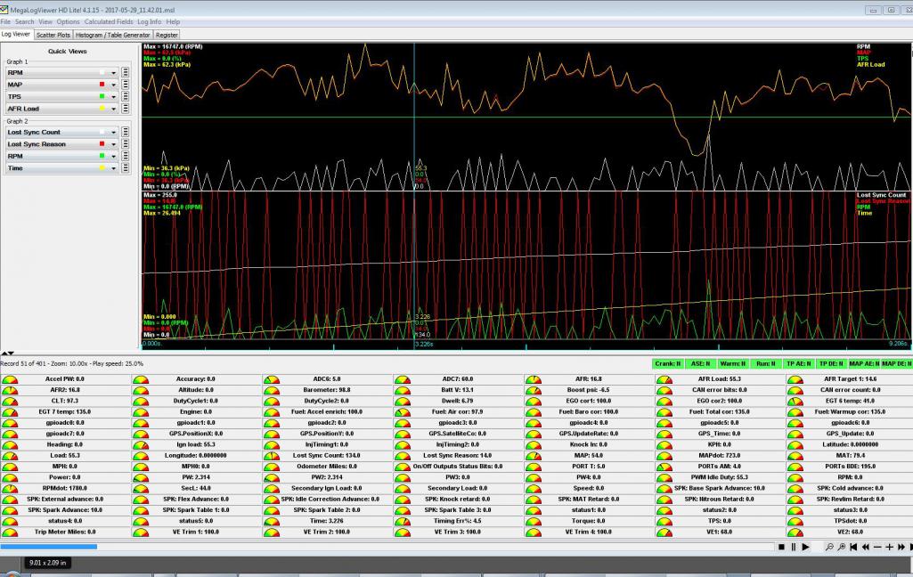 |
|
|
|
| McMark |
May 30 2017, 03:10 PM
Post
#211
|
|
914 Freak! Group: Retired Admin Posts: 20,179 Joined: 13-March 03 From: Grand Rapids, MI Member No.: 419 Region Association: None |
It does NOT like that. See all those red Lost Sync peaks? That's your ECU resetting -- 255 times during your datalog! (IMG:style_emoticons/default/yikes.gif)
|
|
|
|
| timothy_nd28 |
May 30 2017, 03:20 PM
Post
#212
|
|
Advanced Member Group: Members Posts: 2,299 Joined: 25-September 07 From: IN Member No.: 8,154 Region Association: Upper MidWest |
Engine ground would be a problem. If you wired the pull up resistor as shown, then all should be good but 1K ohm seems pretty low. Which color wire did you choose, yellow or white?
I'm sure you could dial this in with time and patience, but I think a VR with a good shielded cable is the better way to go. And if you go that route, might as well ditch the dizzy and do the coil pack dealy. |
|
|
|
| Mblizzard |
May 30 2017, 03:42 PM
Post
#213
|
|
Advanced Member Group: Members Posts: 3,033 Joined: 28-January 13 From: Knoxville Tn Member No.: 15,438 Region Association: South East States |
QUOTE(timothy_nd28 @ May 30 2017, 01:20 PM) Engine ground would be a problem. If you wired the pull up resistor as shown, then all should be good but 1K ohm seems pretty low. Which color wire did you choose, yellow or white? I'm sure you could dial this in with time and patience, but I think a VR with a good shielded cable is the better way to go. And if you go that route, might as well ditch the dizzy and do the coil pack dealy. The VR is in the future but I wanted to do this some what low cost to prove it was possible. Tried both. Yellow first |
|
|
|
| Dtjaden |
May 30 2017, 09:29 PM
Post
#214
|
|
Member Group: Members Posts: 232 Joined: 25-May 13 From: Morgan Hill, CA Member No.: 15,915 Region Association: Northern California |
QUOTE(Mblizzard @ May 30 2017, 02:42 PM) QUOTE(timothy_nd28 @ May 30 2017, 01:20 PM) Engine ground would be a problem. If you wired the pull up resistor as shown, then all should be good but 1K ohm seems pretty low. Which color wire did you choose, yellow or white? I'm sure you could dial this in with time and patience, but I think a VR with a good shielded cable is the better way to go. And if you go that route, might as well ditch the dizzy and do the coil pack dealy. The VR is in the future but I wanted to do this some what low cost to prove it was possible. Tried both. Yellow first This is a kind of off-the-wall option. You could try using a Tach-Adapt box to regenerate a reliable square wave signal. http://www.ashlocktech.com/ The Tach-Adapt is usually used to generate a coil like signal from systems that no longer use distributor/coil systems it it also has the option to do the opposite create low voltage square wave signal that should make the MS somewhat happy. That being said, in one day, if you have someone to help, you can drop the engine, install a 36-1 crank wheel and hall or vr sensor and reinstall the engine. This would be the right way to solve the problem. |
|
|
|
| timothy_nd28 |
May 30 2017, 10:23 PM
Post
#215
|
|
Advanced Member Group: Members Posts: 2,299 Joined: 25-September 07 From: IN Member No.: 8,154 Region Association: Upper MidWest |
I'm totally with you, it's neat to try things outside the box. Triggering the MS from the ignition coil is extremely noisy, lots of ringing going on. I'm sure the MS is perfectly fine with inputs of the Hall or VR signals, but does it have built in filters to shape signals straight from the - terminal of the ignition coil?
Something is funky with the signal from 123 dizzy FI trigger outputs. Consider this as a not so quick test. Reinstall the original distributor and with 2 jumper wires, wire the MS to the distributors old school FI points. You may even have a setting for a reed style switch somewhere in the setup. If so, you wouldn't need any pull up resistors. It would be interesting to see the signal from the old school FI points vs the 123 electronic trigger points. |
|
|
|
| Mblizzard |
May 31 2017, 02:16 AM
Post
#216
|
|
Advanced Member Group: Members Posts: 3,033 Joined: 28-January 13 From: Knoxville Tn Member No.: 15,438 Region Association: South East States |
QUOTE(timothy_nd28 @ May 30 2017, 08:23 PM) I'm totally with you, it's neat to try things outside the box. Triggering the MS from the ignition coil is extremely noisy, lots of ringing going on. I'm sure the MS is perfectly fine with inputs of the Hall or VR signals, but does it have built in filters to shape signals straight from the - terminal of the ignition coil? Something is funky with the signal from 123 dizzy FI trigger outputs. Consider this as a not so quick test. Reinstall the original distributor and with 2 jumper wires, wire the MS to the distributors old school FI points. You may even have a setting for a reed style switch somewhere in the setup. If so, you wouldn't need any pull up resistors. It would be interesting to see the signal from the old school FI points vs the 123 electronic trigger points. Don't have the old one anymore? Got this from Dizzy manufacturer We produce very strange signal on the white and yellow wires. Just good enough for the D-Jetronic system, but not suitable for anything else. 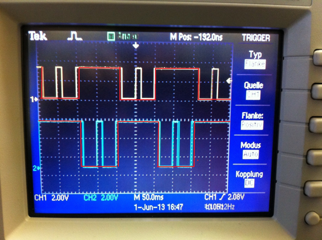 This seems to be what I see in the data logging. And account for the extra pulses. Any thoughts on conditioning? It seems if we could remove the second pulse inside the Square wave it would be perfect. |
|
|
|
| timothy_nd28 |
May 31 2017, 09:08 AM
Post
#217
|
|
Advanced Member Group: Members Posts: 2,299 Joined: 25-September 07 From: IN Member No.: 8,154 Region Association: Upper MidWest |
Strange but a very cool waveform. As the dizzy pulls each bank to ground it releases then hits it again, kinda like a double tap. I wonder why they are doing that for.
Shaping that odd waveform is indeed possible but not very practical. It would be far easier to use the signal from the old distributors FI triggers or buying the VR and trigger wheel kit. Alternatively, my circuit for your LED controller does condition the signal from the ignition coil. I could modify your controller so it has a 5 volt pulse output? |
|
|
|
| VaccaRabite |
May 31 2017, 01:21 PM
Post
#218
|
|
En Garde! Group: Admin Posts: 13,426 Joined: 15-December 03 From: Dallastown, PA Member No.: 1,435 Region Association: MidAtlantic Region |
I highly suggest getting the crank toothed wheel.
You can take the doghouse off with the engine still in the car - I've done it. It isn't a ton of fun, but I have done it. I got the VW air valve, and am looking forward to wiring it in on my car. How are you getting the ECU to control it? Zach |
|
|
|
| Mblizzard |
May 31 2017, 03:48 PM
Post
#219
|
|
Advanced Member Group: Members Posts: 3,033 Joined: 28-January 13 From: Knoxville Tn Member No.: 15,438 Region Association: South East States |
QUOTE(Vacca Rabite @ May 31 2017, 11:21 AM) I highly suggest getting the crank toothed wheel. You can take the doghouse off with the engine still in the car - I've done it. It isn't a ton of fun, but I have done it. I got the VW air valve, and am looking forward to wiring it in on my car. How are you getting the ECU to control it? Zach FIDLE using PWM was able to do the testing in the test part of tuner studio. Will have to pull engine I have AC. |
|
|
|
| Mblizzard |
May 31 2017, 03:54 PM
Post
#220
|
|
Advanced Member Group: Members Posts: 3,033 Joined: 28-January 13 From: Knoxville Tn Member No.: 15,438 Region Association: South East States |
Going to still work the coil option but ordered the Orginal Customs trigger wheel just to be sure.
Just wish it came with free installation. I will buy the beer McMark! (IMG:style_emoticons/default/beer3.gif) (IMG:style_emoticons/default/beer3.gif) (IMG:style_emoticons/default/beer3.gif) |
|
|
|
|
1 User(s) are reading this topic (1 Guests and 0 Anonymous Users)
0 Members:

|
Lo-Fi Version | Time is now: 28th April 2024 - 04:04 PM |
Invision Power Board
v9.1.4 © 2024 IPS, Inc.