|
|
|
Porsche, and the Porsche crest are registered trademarks of Dr. Ing. h.c. F. Porsche AG.
This site is not affiliated with Porsche in any way. Its only purpose is to provide an online forum for car enthusiasts. All other trademarks are property of their respective owners. |
|
|


| tygaboy |
 Oct 17 2016, 10:56 AM Oct 17 2016, 10:56 AM
Post
#1861
|
|
914 Guru  Group: Members Posts: 5,826 Joined: 6-October 15 From: Petaluma, CA Member No.: 19,241 Region Association: Northern California |
Hi World!
Let the games begin! (IMG:style_emoticons/default/piratenanner.gif) As the title says, it's a '75 that's getting an LS3 (Cracker's "old" motor - thanks Tony!) and Boxster 6 speed. Also planned is zippidy doo-dah 911 front suspension with Boxster calipers all around. The rear suspension is getting 911 ebrakes, Tangerine Racing raised pickups and shock towers. I have plans to stiffen the chassis with a partial cage. Doesn't that sound like a great plan? I think so, too! BACKGROUND: I got this as a roller that was purported to be "dry and accident free". And it was! Except for all the rust and the place where it was hit. Yeah, yeah... But it's all good. The seller and I worked everything out. (IMG:style_emoticons/default/beerchug.gif) But our little 914s are full of surprises and isn't that half the fun? So, first up is rust repair time! (IMG:style_emoticons/default/sawzall-smiley.gif) (IMG:style_emoticons/default/sawzall-smiley.gif) (IMG:style_emoticons/default/welder.gif) (IMG:style_emoticons/default/welder.gif) Let's begin with some pics of what I started with. Wish me luck! Wait, forget the luck, wish me SKILL!!! Attached image(s) 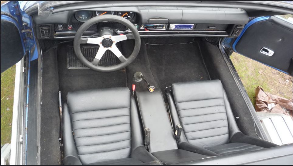 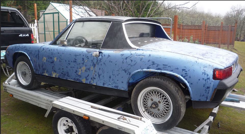
|
   |

 
|
Posts in this topic
tygaboy BUILD-OFF CHALLENGE: Tygaboy's '75 LS3 Oct 17 2016, 10:56 AM tygaboy Hey, looks pretty good! Let's have a look ... Oct 17 2016, 10:58 AM tygaboy How about the hell hole? Hmmm. Oct 17 2016, 11:00 AM tygaboy The outer longs? Pretty nice! No problem! ... Oct 17 2016, 11:07 AM tygaboy Forgot the pic of the outer longs... Oct 17 2016, 11:08 AM tygaboy A real contributing factor to the rust issue was f... Oct 17 2016, 11:11 AM tygaboy So... NOW we'll let the games begin. And I wan... Oct 17 2016, 11:26 AM Cracker Good "skill" Chris...do that motor proud... Oct 17 2016, 12:12 PM
 tygaboy
Good "skill" Chris...do that motor prou... Oct 17 2016, 12:32 PM Mueller Whoa, that is going to be a little bit of work... Oct 17 2016, 12:55 PM tygaboy In planning the fabrication of the sleeves needed ... Oct 17 2016, 01:00 PM tygaboy I sliced the longitudinal repair section out of my... Oct 17 2016, 01:11 PM Racer Chris
I'm using Tangerine Racing's door brace ... Oct 17 2016, 01:25 PM tygaboy
[quote name='tygaboy' post='2412396' date='Oct 17... Oct 17 2016, 01:57 PM Racer Chris
...
Here's my super high-tech design. No doub... Oct 17 2016, 02:16 PM tygaboy Hell hole/long repair welding nearly completed... Oct 17 2016, 02:01 PM tygaboy My paranoia paid off and another Tangerine product... Oct 17 2016, 02:10 PM tygaboy CHASSIS STIFFENING: Version 1
LS3 = I need to sti... Oct 20 2016, 11:27 AM tygaboy CHASSIS STIFFENING:Version 1
From a design perspe... Oct 20 2016, 11:35 AM tygaboy CHASSIS STIFFENING: Version II - Change of Plan
A... Oct 20 2016, 11:51 AM worn
That said, I also wanted to hide as much of this... Oct 20 2016, 01:09 PM stevegm Interesting idea. It should provide some stiffness... Oct 20 2016, 12:15 PM Cairo94507 Now that is a very cool way to stiffen the car and... Oct 20 2016, 12:42 PM Cracker Very nice Chris...have it running at WCR! :sh... Oct 20 2016, 12:49 PM 914forme Very nice bar tuck. If your not planning on runni... Oct 23 2016, 09:48 AM tygaboy
Very nice bar tuck. If your not planning on runn... Oct 23 2016, 01:25 PM tygaboy CHASSIS STIFFENING: Front Hoop/Door Bars
In keepi... Oct 23 2016, 01:42 PM tygaboy CHASSIS STIFFENING: Con'd
Next, I started on ... Oct 23 2016, 01:51 PM Rand I don't think you need three verts. My choice ... Oct 23 2016, 02:00 PM Cracker Chris - You don't need to have your bar that h... Oct 23 2016, 03:39 PM tygaboy
Chris - You don't need to have your bar that ... Oct 23 2016, 05:26 PM Rand
Curious what your thoughts are on simply running... Oct 28 2016, 06:17 PM tygaboy
Curious what your thoughts are on simply runnin... Oct 28 2016, 06:21 PM Rand
I'm pretty sure that angle would make it toug... Oct 28 2016, 06:33 PM tygaboy
[quote name='tygaboy' post='2417024' date='Oct 28... Oct 28 2016, 08:12 PM mgp4591
[quote name='tygaboy' post='2417024' date='Oct 28... Nov 5 2016, 03:31 AM tygaboy Oh boy. oh boy... is this going to be a full weeke... Oct 28 2016, 05:58 PM Mueller I'd throw a seat in there 1st and test how muc... Oct 28 2016, 06:07 PM tygaboy
I'd throw a seat in there 1st and test how mu... Oct 28 2016, 06:22 PM Mueller
I'd throw a seat in there 1st and test how m... Oct 28 2016, 07:17 PM Dion Fantastic fabrication. Way to go Chris. I'm ... Oct 28 2016, 06:56 PM Cracker Something else to consider when designing your str... Oct 28 2016, 08:37 PM tygaboy CHASSIS STIFFENING: Inner Longs
Got started on th... Oct 29 2016, 10:01 AM Mueller
CHASSIS STIFFENING: Inner Longs
Got started on t... Oct 29 2016, 10:05 AM tygaboy Details, details... trim to fit - even the little ... Oct 29 2016, 10:04 AM tygaboy Fitting the left side... This went way faster as I... Oct 29 2016, 06:13 PM Rand Nice. You don't need a bunch of tubage. This a... Oct 29 2016, 06:17 PM tygaboy
Nice. You don't need a bunch of tubage. This ... Oct 29 2016, 06:24 PM Rand
Nice. You don't need a bunch of tubage. This... Oct 29 2016, 06:35 PM tygaboy Another. And if you need to make large holes for t... Oct 29 2016, 06:19 PM Cracker Your picture reminds me of a Fred Flintstone mobil... Oct 29 2016, 06:47 PM tygaboy Artsy shot of the day. I just love the smooth, cle... Oct 29 2016, 06:20 PM tygaboy CHASSIS STIFFENING: Lower Firewall
Today's re... Oct 30 2016, 09:53 AM tygaboy Then it's roll, check, roll, check. Manual rol... Oct 30 2016, 09:55 AM tygaboy Looks good to me! Oct 30 2016, 09:56 AM tygaboy I'm not so confident that I trust my measureme... Oct 30 2016, 03:30 PM tygaboy In the pics above, the rear floor is just held in ... Oct 30 2016, 03:36 PM Cracker Chris,
I like it. One word of caution; however, d... Oct 30 2016, 05:47 PM tygaboy Suspension porn! Got my trailing arms back fro... Oct 30 2016, 06:37 PM Cracker Damn right those are slick...Foley does excellent ... Oct 30 2016, 06:47 PM 914forme Oh wow our builds are very close, I like what your... Oct 30 2016, 07:55 PM 1stworks Following.
Thanks for sharing. Oct 31 2016, 05:52 PM Curbandgutter Wow the build is looking great. I really liked yo... Nov 2 2016, 05:08 PM tygaboy Engine & Trans: Mock Up
November activities c... Nov 4 2016, 05:22 PM tygaboy As I'm looking at this wild set up, I leaned u... Nov 4 2016, 05:27 PM 914forme All that tooling in your shop I am just :drooley:... Nov 5 2016, 09:37 AM tygaboy
All that tooling in your shop I am just :drooley... Nov 5 2016, 09:56 AM tygaboy It was a frustrating weekend in that I didn't ... Nov 6 2016, 06:02 PM tygaboy So the only progress to report for this weekend is... Nov 6 2016, 06:05 PM tygaboy And after all this hard work, I'm adding a lit... Nov 6 2016, 06:10 PM JmuRiz Amazing how compact an LS motor is! Nov 6 2016, 06:21 PM Krieger Nice work Chris! You are making amazing progr... Nov 6 2016, 07:36 PM Cracker Something else that just came to mind Chris...if y... Nov 6 2016, 07:40 PM tygaboy
Something else that just came to mind Chris...if ... Nov 6 2016, 07:49 PM tygaboy So... the good/bad news is that this week I had my... Nov 12 2016, 05:26 PM tygaboy I have a bit of 50" wide, 2x2 twill weave lef... Nov 12 2016, 05:29 PM tygaboy A little mold release wax and PVA, then 2 layers o... Nov 12 2016, 05:32 PM tygaboy And before you ask, yes, these covers are purely e... Nov 13 2016, 09:23 AM Cracker Sweet, Chris...I can certify that you won't n... Nov 13 2016, 09:29 AM tygaboy A couple of pics to give you the idea.
I may have ... Nov 13 2016, 09:36 AM tygaboy Well this was a "long" weekend! :lo... Nov 13 2016, 03:47 PM Dion Fantastic work Chris. Nov 13 2016, 04:05 PM tygaboy
Fantastic work Chris.
Thanks for the kind words... Nov 13 2016, 04:59 PM Curbandgutter I like your carbon fiber idea. I just may shameles... Nov 13 2016, 04:22 PM tygaboy
I like your carbon fiber idea. I just may shamele... Nov 13 2016, 04:57 PM tygaboy Before I install the long stiffeners, I need to cl... Nov 18 2016, 06:30 PM Rand The ebrake void I get. But, don't bother weldi... Nov 18 2016, 10:03 PM tygaboy
The ebrake void I get. But, don't bother weld... Nov 18 2016, 10:58 PM Rand
The ebrake void I get. But, don't bother wel... Nov 19 2016, 12:34 AM tygaboy Well, if Rand is concerned I'm overdoing it re... Nov 19 2016, 01:59 PM Rand No concerns, lol. Just banter. :trophy: Nov 19 2016, 02:02 PM tygaboy Major milestone! Got the engine and trans mock... Nov 20 2016, 06:41 PM Wew Wow, well done Chris! :beer1: Nov 20 2016, 08:20 PM tygaboy With the trans located, I could verify the shifter... Nov 22 2016, 12:57 PM tygaboy OK, even I'm getting tired of pictures of this... Nov 23 2016, 07:04 PM tygaboy A little holiday video of the H press in use bendi... Nov 24 2016, 09:41 AM tygaboy Some of this fab work isn't the most exciting ... Nov 25 2016, 07:30 PM 914forme :agree: It is very easy to push your mounts forwar... Nov 27 2016, 05:59 PM tygaboy
:agree: It is very easy to push your mounts forwa... Nov 27 2016, 06:25 PM tygaboy My optimism regarding how much I'd get done th... Nov 27 2016, 06:23 PM
tygaboy
Good "skill" Chris...do that motor prou... Oct 17 2016, 12:32 PM Mueller Whoa, that is going to be a little bit of work... Oct 17 2016, 12:55 PM tygaboy In planning the fabrication of the sleeves needed ... Oct 17 2016, 01:00 PM tygaboy I sliced the longitudinal repair section out of my... Oct 17 2016, 01:11 PM Racer Chris
I'm using Tangerine Racing's door brace ... Oct 17 2016, 01:25 PM tygaboy
[quote name='tygaboy' post='2412396' date='Oct 17... Oct 17 2016, 01:57 PM Racer Chris
...
Here's my super high-tech design. No doub... Oct 17 2016, 02:16 PM tygaboy Hell hole/long repair welding nearly completed... Oct 17 2016, 02:01 PM tygaboy My paranoia paid off and another Tangerine product... Oct 17 2016, 02:10 PM tygaboy CHASSIS STIFFENING: Version 1
LS3 = I need to sti... Oct 20 2016, 11:27 AM tygaboy CHASSIS STIFFENING:Version 1
From a design perspe... Oct 20 2016, 11:35 AM tygaboy CHASSIS STIFFENING: Version II - Change of Plan
A... Oct 20 2016, 11:51 AM worn
That said, I also wanted to hide as much of this... Oct 20 2016, 01:09 PM stevegm Interesting idea. It should provide some stiffness... Oct 20 2016, 12:15 PM Cairo94507 Now that is a very cool way to stiffen the car and... Oct 20 2016, 12:42 PM Cracker Very nice Chris...have it running at WCR! :sh... Oct 20 2016, 12:49 PM 914forme Very nice bar tuck. If your not planning on runni... Oct 23 2016, 09:48 AM tygaboy
Very nice bar tuck. If your not planning on runn... Oct 23 2016, 01:25 PM tygaboy CHASSIS STIFFENING: Front Hoop/Door Bars
In keepi... Oct 23 2016, 01:42 PM tygaboy CHASSIS STIFFENING: Con'd
Next, I started on ... Oct 23 2016, 01:51 PM Rand I don't think you need three verts. My choice ... Oct 23 2016, 02:00 PM Cracker Chris - You don't need to have your bar that h... Oct 23 2016, 03:39 PM tygaboy
Chris - You don't need to have your bar that ... Oct 23 2016, 05:26 PM Rand
Curious what your thoughts are on simply running... Oct 28 2016, 06:17 PM tygaboy
Curious what your thoughts are on simply runnin... Oct 28 2016, 06:21 PM Rand
I'm pretty sure that angle would make it toug... Oct 28 2016, 06:33 PM tygaboy
[quote name='tygaboy' post='2417024' date='Oct 28... Oct 28 2016, 08:12 PM mgp4591
[quote name='tygaboy' post='2417024' date='Oct 28... Nov 5 2016, 03:31 AM tygaboy Oh boy. oh boy... is this going to be a full weeke... Oct 28 2016, 05:58 PM Mueller I'd throw a seat in there 1st and test how muc... Oct 28 2016, 06:07 PM tygaboy
I'd throw a seat in there 1st and test how mu... Oct 28 2016, 06:22 PM Mueller
I'd throw a seat in there 1st and test how m... Oct 28 2016, 07:17 PM Dion Fantastic fabrication. Way to go Chris. I'm ... Oct 28 2016, 06:56 PM Cracker Something else to consider when designing your str... Oct 28 2016, 08:37 PM tygaboy CHASSIS STIFFENING: Inner Longs
Got started on th... Oct 29 2016, 10:01 AM Mueller
CHASSIS STIFFENING: Inner Longs
Got started on t... Oct 29 2016, 10:05 AM tygaboy Details, details... trim to fit - even the little ... Oct 29 2016, 10:04 AM tygaboy Fitting the left side... This went way faster as I... Oct 29 2016, 06:13 PM Rand Nice. You don't need a bunch of tubage. This a... Oct 29 2016, 06:17 PM tygaboy
Nice. You don't need a bunch of tubage. This ... Oct 29 2016, 06:24 PM Rand
Nice. You don't need a bunch of tubage. This... Oct 29 2016, 06:35 PM tygaboy Another. And if you need to make large holes for t... Oct 29 2016, 06:19 PM Cracker Your picture reminds me of a Fred Flintstone mobil... Oct 29 2016, 06:47 PM tygaboy Artsy shot of the day. I just love the smooth, cle... Oct 29 2016, 06:20 PM tygaboy CHASSIS STIFFENING: Lower Firewall
Today's re... Oct 30 2016, 09:53 AM tygaboy Then it's roll, check, roll, check. Manual rol... Oct 30 2016, 09:55 AM tygaboy Looks good to me! Oct 30 2016, 09:56 AM tygaboy I'm not so confident that I trust my measureme... Oct 30 2016, 03:30 PM tygaboy In the pics above, the rear floor is just held in ... Oct 30 2016, 03:36 PM Cracker Chris,
I like it. One word of caution; however, d... Oct 30 2016, 05:47 PM tygaboy Suspension porn! Got my trailing arms back fro... Oct 30 2016, 06:37 PM Cracker Damn right those are slick...Foley does excellent ... Oct 30 2016, 06:47 PM 914forme Oh wow our builds are very close, I like what your... Oct 30 2016, 07:55 PM 1stworks Following.
Thanks for sharing. Oct 31 2016, 05:52 PM Curbandgutter Wow the build is looking great. I really liked yo... Nov 2 2016, 05:08 PM tygaboy Engine & Trans: Mock Up
November activities c... Nov 4 2016, 05:22 PM tygaboy As I'm looking at this wild set up, I leaned u... Nov 4 2016, 05:27 PM 914forme All that tooling in your shop I am just :drooley:... Nov 5 2016, 09:37 AM tygaboy
All that tooling in your shop I am just :drooley... Nov 5 2016, 09:56 AM tygaboy It was a frustrating weekend in that I didn't ... Nov 6 2016, 06:02 PM tygaboy So the only progress to report for this weekend is... Nov 6 2016, 06:05 PM tygaboy And after all this hard work, I'm adding a lit... Nov 6 2016, 06:10 PM JmuRiz Amazing how compact an LS motor is! Nov 6 2016, 06:21 PM Krieger Nice work Chris! You are making amazing progr... Nov 6 2016, 07:36 PM Cracker Something else that just came to mind Chris...if y... Nov 6 2016, 07:40 PM tygaboy
Something else that just came to mind Chris...if ... Nov 6 2016, 07:49 PM tygaboy So... the good/bad news is that this week I had my... Nov 12 2016, 05:26 PM tygaboy I have a bit of 50" wide, 2x2 twill weave lef... Nov 12 2016, 05:29 PM tygaboy A little mold release wax and PVA, then 2 layers o... Nov 12 2016, 05:32 PM tygaboy And before you ask, yes, these covers are purely e... Nov 13 2016, 09:23 AM Cracker Sweet, Chris...I can certify that you won't n... Nov 13 2016, 09:29 AM tygaboy A couple of pics to give you the idea.
I may have ... Nov 13 2016, 09:36 AM tygaboy Well this was a "long" weekend! :lo... Nov 13 2016, 03:47 PM Dion Fantastic work Chris. Nov 13 2016, 04:05 PM tygaboy
Fantastic work Chris.
Thanks for the kind words... Nov 13 2016, 04:59 PM Curbandgutter I like your carbon fiber idea. I just may shameles... Nov 13 2016, 04:22 PM tygaboy
I like your carbon fiber idea. I just may shamele... Nov 13 2016, 04:57 PM tygaboy Before I install the long stiffeners, I need to cl... Nov 18 2016, 06:30 PM Rand The ebrake void I get. But, don't bother weldi... Nov 18 2016, 10:03 PM tygaboy
The ebrake void I get. But, don't bother weld... Nov 18 2016, 10:58 PM Rand
The ebrake void I get. But, don't bother wel... Nov 19 2016, 12:34 AM tygaboy Well, if Rand is concerned I'm overdoing it re... Nov 19 2016, 01:59 PM Rand No concerns, lol. Just banter. :trophy: Nov 19 2016, 02:02 PM tygaboy Major milestone! Got the engine and trans mock... Nov 20 2016, 06:41 PM Wew Wow, well done Chris! :beer1: Nov 20 2016, 08:20 PM tygaboy With the trans located, I could verify the shifter... Nov 22 2016, 12:57 PM tygaboy OK, even I'm getting tired of pictures of this... Nov 23 2016, 07:04 PM tygaboy A little holiday video of the H press in use bendi... Nov 24 2016, 09:41 AM tygaboy Some of this fab work isn't the most exciting ... Nov 25 2016, 07:30 PM 914forme :agree: It is very easy to push your mounts forwar... Nov 27 2016, 05:59 PM tygaboy
:agree: It is very easy to push your mounts forwa... Nov 27 2016, 06:25 PM tygaboy My optimism regarding how much I'd get done th... Nov 27 2016, 06:23 PM  |
3 User(s) are reading this topic (3 Guests and 0 Anonymous Users)
0 Members:

|
Lo-Fi Version | Time is now: 7th June 2026 - 01:22 PM |
Invision Power Board
v9.1.4 © 2026 IPS, Inc.