|
|
|
Porsche, and the Porsche crest are registered trademarks of Dr. Ing. h.c. F. Porsche AG.
This site is not affiliated with Porsche in any way. Its only purpose is to provide an online forum for car enthusiasts. All other trademarks are property of their respective owners. |
|
|

  |

| 914dave |
 Jan 26 2017, 10:14 AM Jan 26 2017, 10:14 AM
Post
#221
|
|
914 Addict  Group: Members Posts: 740 Joined: 19-October 03 From: Willow Grove Pa. Member No.: 1,262 Region Association: North East States |
Really nice work! I like the details. |
   |

 
|
| tygaboy |
Jan 28 2017, 09:13 AM
Post
#222
|
|
914 Guru Group: Members Posts: 5,817 Joined: 6-October 15 From: Petaluma, CA Member No.: 19,241 Region Association: Northern California |
I changed my mind! (Nothing new there...) I decided that I want to run the console the length of the tunnel, from under the front roll hoop to the firewall, so I started playing with designs.
Here's a reminder pic of the 'shorty' Version 1 again, along with the new design. Version 2 is taller up front to get the shifter to the desired height. This is just brainstorming as I still need to work out things like where the cup holders will go... Attached thumbnail(s) 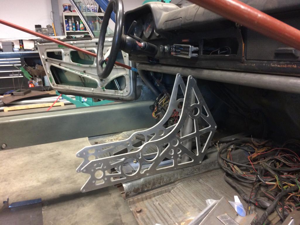 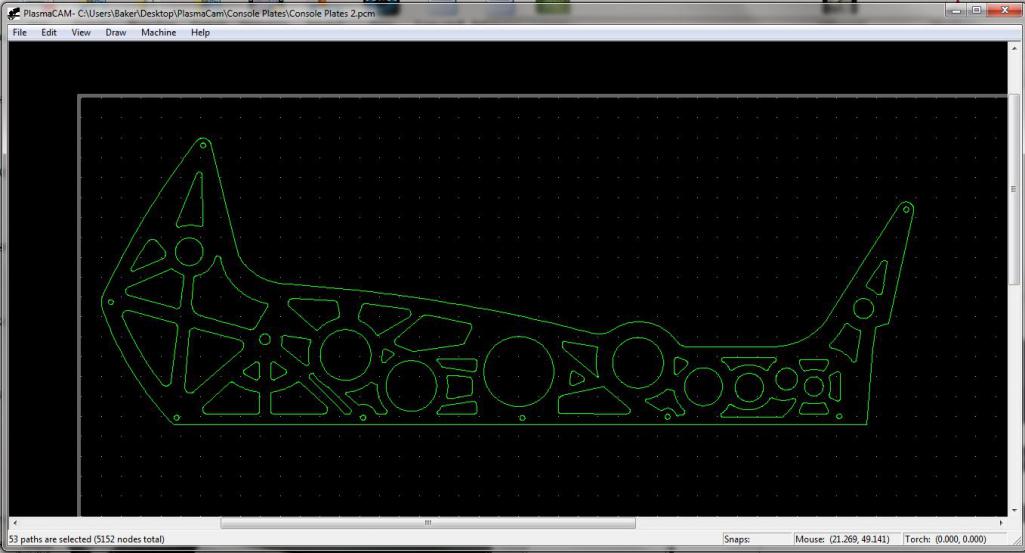
|
|
|
|
| Cracker |
Jan 28 2017, 09:17 AM
Post
#223
|
|
Advanced Member Group: Members Posts: 2,148 Joined: 2-February 10 From: Atlanta (area) Member No.: 11,316 Region Association: South East States |
Chris: Honestly, it looks a little busy (to me). Are all of those "lightening holes" going to be exposed? There can be elegance in simplicity, ehh? Maybe I would like it more as a completed unit...cut it out!
PS: How about adapting a similar design to the rear shock tower panel to the console? Cool as hell and aesthetically tied to other components...you are doing a great (great!) job. These are just my thoughts...pal. T |
|
|
|
| tygaboy |
Jan 28 2017, 09:34 AM
Post
#224
|
|
914 Guru Group: Members Posts: 5,817 Joined: 6-October 15 From: Petaluma, CA Member No.: 19,241 Region Association: Northern California |
QUOTE(Cracker @ Jan 28 2017, 07:17 AM)  Chris: Honestly, it looks a little busy (to me). Are all of those "lightening holes" going to be exposed? There can be elegance in simplicity, ehh? Maybe I would like it more as a completed unit...cut it out! T I know what you mean. I'm still playing and as I've proven to myself time and again, I need to get a physical example in my hands, see it in place and then think on it before I land on what I like. All I know for sure is it won't look like it does now! Keep the comments coming - your perspective is always appreciated. Chris |
|
|
|
| Curbandgutter |
Jan 28 2017, 10:56 AM
Post
#225
|
|
Senior Member Group: Members Posts: 566 Joined: 8-March 13 From: Murrieta CA Member No.: 15,637 Region Association: Southern California |
Chris you're doing a great job and you did say you want the comments coming right? I'm with Tony, make it a little simpler. Maybe something that has a combination of lightening holes and triangles that reveals a strut form. It seems too ornate. But heck if I had access to that plasma cutter I'd probably make something that looks like bad freeway art......you know like something that could be found in an Aztec pyramid.
|
|
|
|
| tygaboy |
Jan 28 2017, 11:08 AM
Post
#226
|
|
914 Guru Group: Members Posts: 5,817 Joined: 6-October 15 From: Petaluma, CA Member No.: 19,241 Region Association: Northern California |
Yep, yep, it'll be simpler. And speaking of things one can make with a plasma table, here's a sneak at something I'll be cutting soon.
A 4 foot tall crest! I plan to hang it in my office. I'm cutting it in layers so the various elements will stand off the background of the crest. Should be pretty cool. If I can fit it, I'll bring it to the WCR in June! Attached thumbnail(s) 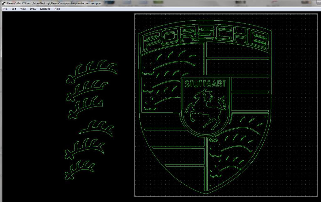
|
|
|
|
| Cracker |
Jan 28 2017, 11:14 AM
Post
#227
|
|
Advanced Member Group: Members Posts: 2,148 Joined: 2-February 10 From: Atlanta (area) Member No.: 11,316 Region Association: South East States |
Please make a second copy for my hauler or shop...I won't charge you for my criticism - even trade! (IMG:style_emoticons/default/poke.gif)
Tony QUOTE(tygaboy @ Jan 28 2017, 12:08 PM) Yep, yep, it'll be simpler. And speaking of things one can make with a plasma table, here's a sneak at something I'll be cutting soon. A 4 foot tall crest! I plan to hand it in my office. I'm cutting it in layers so the various elements will stand off the background of the crest. Should be pretty cool. If I can fit it, I'll bring it to the WCR in June! |
|
|
|
| tygaboy |
Jan 28 2017, 04:51 PM
Post
#228
|
|
914 Guru Group: Members Posts: 5,817 Joined: 6-October 15 From: Petaluma, CA Member No.: 19,241 Region Association: Northern California |
I was swamped at work this week so didn't get any after-hours shop time so spent part of today completing V2 of the panel. The plasma table is just so cool!
Here's the panel after trimming/fitting. It looks so much better with the top line following the crossbar arch all the way across. I'm REALLY happy with how I got it to fit. Nice and tight: (IMG:style_emoticons/default/sheeplove.gif) Attached thumbnail(s) 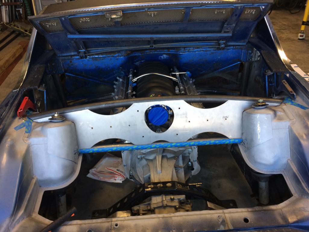 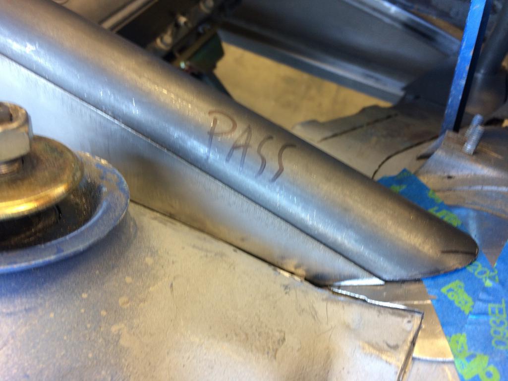
|
|
|
|
| tygaboy |
Jan 28 2017, 04:58 PM
Post
#229
|
|
914 Guru Group: Members Posts: 5,817 Joined: 6-October 15 From: Petaluma, CA Member No.: 19,241 Region Association: Northern California |
Then it was back to the knock-out punches and dimple dies. I did the same bead rolled tip edge on the large top and bottom openings.
I am so much happier with this design over the first one. The shape of the intake opening, the fact that the opening stays within the panel. Much better. So I've proved yet again that I need to get a look at things in place on the car vs. on a computer screen. Maybe I'll get better at this. It'd sure be more efficient, both in time and cost. So if you couldn't tell, I really like this piece. (Know anyone who wants to buy V1? (IMG:style_emoticons/default/laugh.gif) ) Attached thumbnail(s) 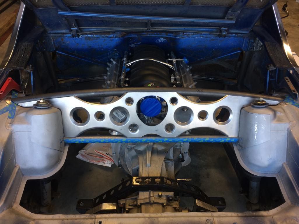 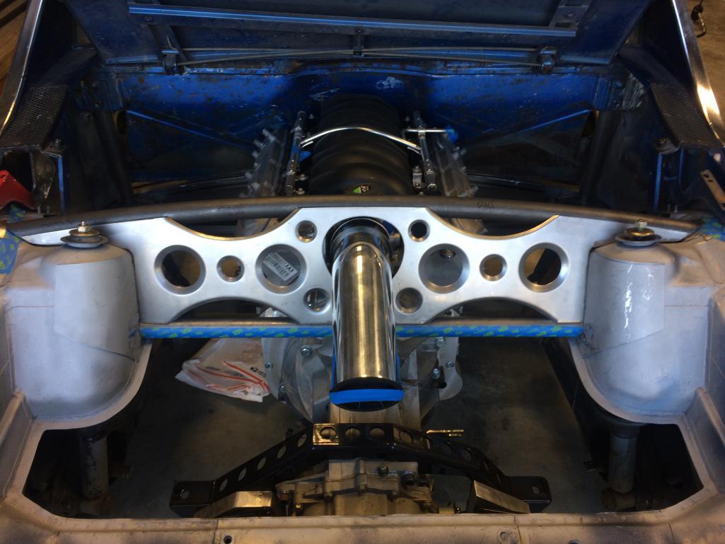
|
|
|
|
| Cracker |
Jan 28 2017, 05:00 PM
Post
#230
|
|
Advanced Member Group: Members Posts: 2,148 Joined: 2-February 10 From: Atlanta (area) Member No.: 11,316 Region Association: South East States |
Badass - love it!
T |
|
|
|
| Andyrew |
Jan 28 2017, 05:12 PM
Post
#231
|
|
Spooling.... Please wait Group: Members Posts: 13,380 Joined: 20-January 03 From: Riverbank, Ca Member No.: 172 Region Association: Northern California |
The stuff you can do with a plasma cutter...
Looks great! I agree the center console is a bit complex but it does look strong (IMG:style_emoticons/default/smile.gif) |
|
|
|
| tygaboy |
Jan 29 2017, 08:07 PM
Post
#232
|
|
914 Guru Group: Members Posts: 5,817 Joined: 6-October 15 From: Petaluma, CA Member No.: 19,241 Region Association: Northern California |
I, too, think that initial console design is messy. Im redoing it and will post once V2 is ready for its debut.
Most of today was spent reorganizing the shop. It had gotten to the point where I could barely get around. Much better now. So not much to report other than starting to work up the design for the rear trans mount. Having moved the drive train forward, there's more leverage on the existing trans mounts so I want to add the rear mount. Probably not really needed but I like to have a little insurance, just to be sure. I'm still at the "hmmm, maybe this would work..." stage. These low bars will be triangulated with bars that run from the top are of the shock towers and tie into them at the trans cross brace. It may be that the top bars extend to the rear mount and the low bars tie into them. And these are just pieces I had laying around so it's all up for grabs. As I said, I'm still playing with design while trying to account for things like a removable trunk liner, etc. Fun all around! Attached thumbnail(s) 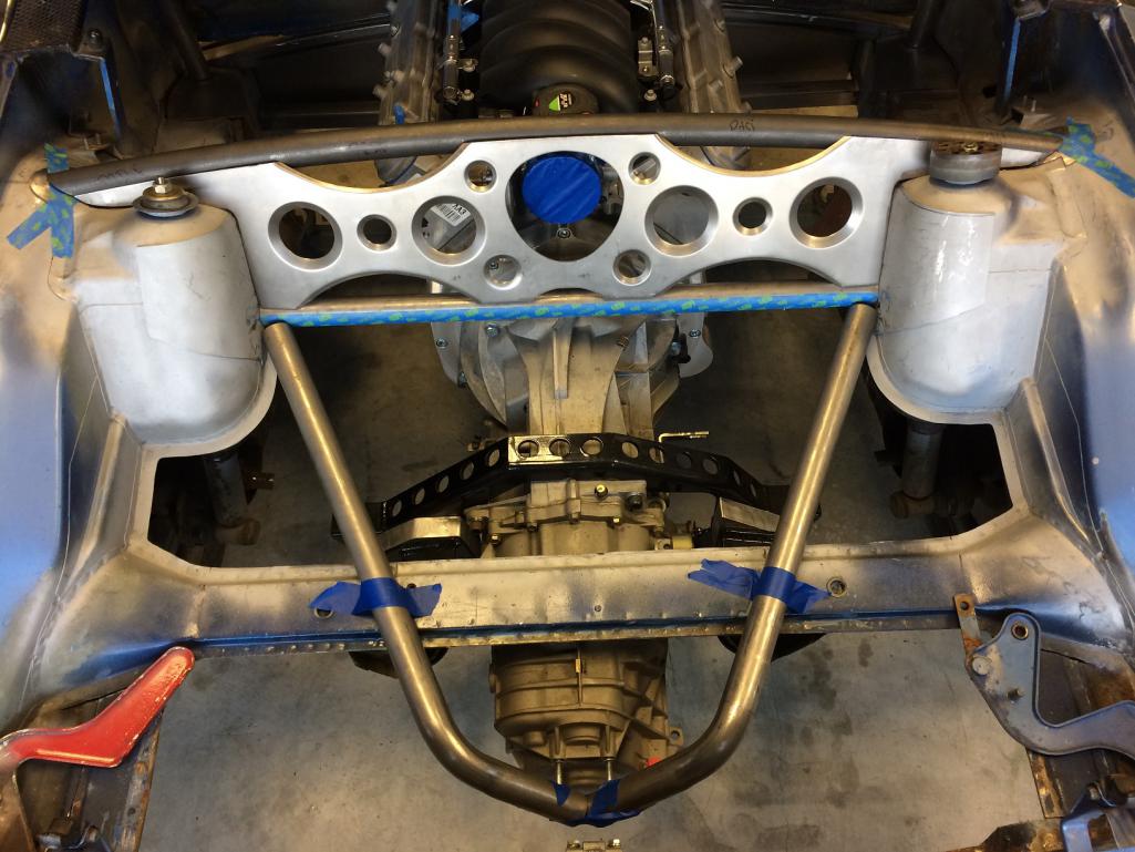 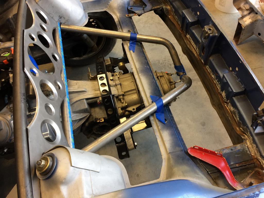
|
|
|
|
| tygaboy |
Jan 30 2017, 08:26 AM
Post
#233
|
|
914 Guru Group: Members Posts: 5,817 Joined: 6-October 15 From: Petaluma, CA Member No.: 19,241 Region Association: Northern California |
Uh oh, this can't be good...
I think I may make panel V3. This one would be aluminum plate cut on a water jet, just like the shorty console plate. It would bolt to bosses welded to the cross bars and shock towers. It'd be a way bigger deal to do but... I'm thinking I'd back it up with a carbon fiber panel. (IMG:style_emoticons/default/drooley.gif) Yes, I know I'll eventually need to decide and move on. But this design makes it far simpler for me to seal up the trunk area and keep (most of) the heat away from the intake and top, when it's stored. We shall see. Attached thumbnail(s) 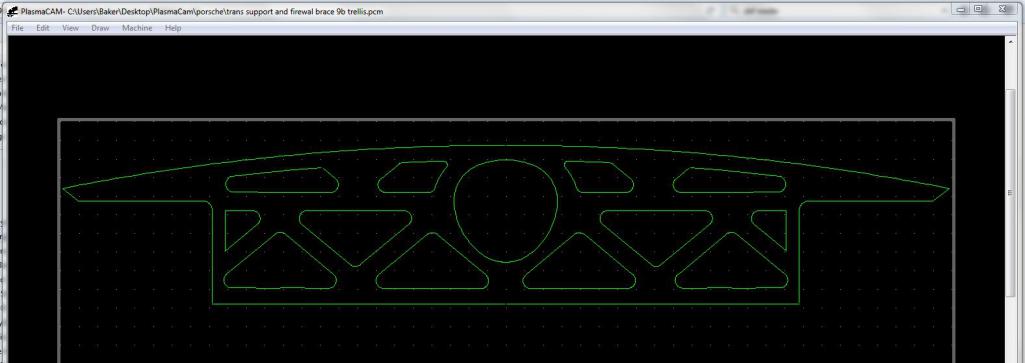
|
|
|
|
| mbseto |
Jan 30 2017, 12:02 PM
Post
#234
|
|
Senior Member Group: Members Posts: 1,257 Joined: 6-August 14 From: Cincy Member No.: 17,743 Region Association: North East States |
Love the flourishes. Shows a confident build.
|
|
|
|
| tygaboy |
Jan 30 2017, 12:56 PM
Post
#235
|
|
914 Guru Group: Members Posts: 5,817 Joined: 6-October 15 From: Petaluma, CA Member No.: 19,241 Region Association: Northern California |
In planning the rear trans mount, I opted not to use the stock Boxster mount, nice as it was, all cast aluminum and all. It positioned the attachment point high. So I'm playing with designs for a mount that will keep everything under the height of the stock trunk floor's level.
This time, I'm going to try cutting the whole part and folding the sides and top into position for welding. Attached image(s) 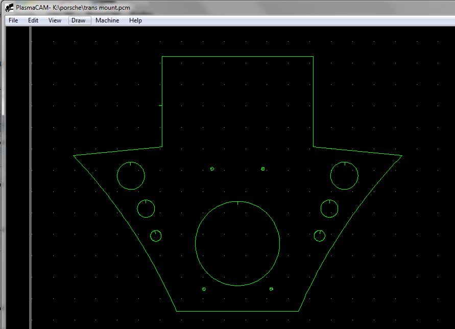
|
|
|
|
| tygaboy |
Jan 30 2017, 01:05 PM
Post
#236
|
|
914 Guru Group: Members Posts: 5,817 Joined: 6-October 15 From: Petaluma, CA Member No.: 19,241 Region Association: Northern California |
QUOTE(mbseto @ Jan 30 2017, 10:02 AM) Love the flourishes. Shows a confident build. Back at you! Your motor mount fab (very nice, btw...) inspired me to give the folding a try. |
|
|
|
| tygaboy |
Jan 31 2017, 12:02 PM
Post
#237
|
|
914 Guru Group: Members Posts: 5,817 Joined: 6-October 15 From: Petaluma, CA Member No.: 19,241 Region Association: Northern California |
Last night, I cut and folded the rear trans mount. Here it is, before seam welding. And it turned out just like it was supposed to... Thing is, I don't like it. Too bulky, bigger than it really needs to be.
So January closes with another "let's do it differently on the next one!" (IMG:style_emoticons/default/dry.gif) At least I'm consistent! Attached thumbnail(s) 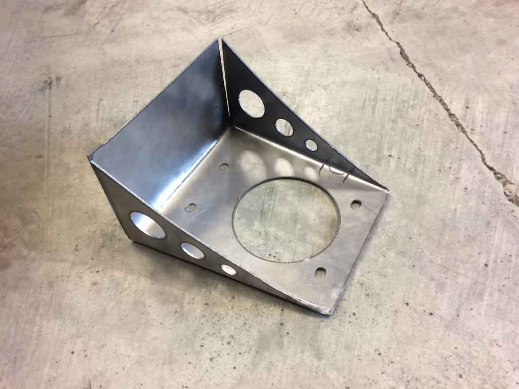
|
|
|
|
| tygaboy |
Jan 31 2017, 12:10 PM
Post
#238
|
|
914 Guru Group: Members Posts: 5,817 Joined: 6-October 15 From: Petaluma, CA Member No.: 19,241 Region Association: Northern California |
As long as I had the plasma machine fired up, I figured I'd play with a design for load distribution/attaching the lower stiffening bars. These would have sheet metal closing in the tops.
I may mock up a design that uses these pieces on the outside of the bars but where the inner piece runs all the way across between them. My first thought when I set these in place was "Holy holes, Batman!" I need to be careful of a couple things: 1. Too much of one design element and, 2. Creating a bunch of nooks and crannies for crap to get into Attached thumbnail(s) 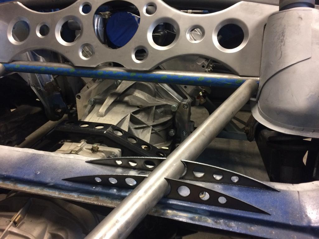
|
|
|
|
| tygaboy |
Jan 31 2017, 12:17 PM
Post
#239
|
|
914 Guru Group: Members Posts: 5,817 Joined: 6-October 15 From: Petaluma, CA Member No.: 19,241 Region Association: Northern California |
another
Attached thumbnail(s) 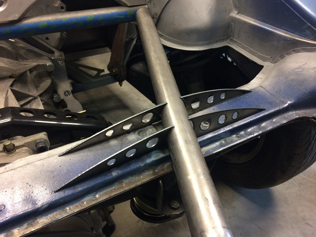
|
|
|
|
| tygaboy |
Feb 3 2017, 11:39 AM
Post
#240
|
|
914 Guru Group: Members Posts: 5,817 Joined: 6-October 15 From: Petaluma, CA Member No.: 19,241 Region Association: Northern California |
And here's the new rear trans mount design. It's more compact and I think looks better, too. Function and form... Win-win! (IMG:style_emoticons/default/smilie_pokal.gif)
Attached thumbnail(s) 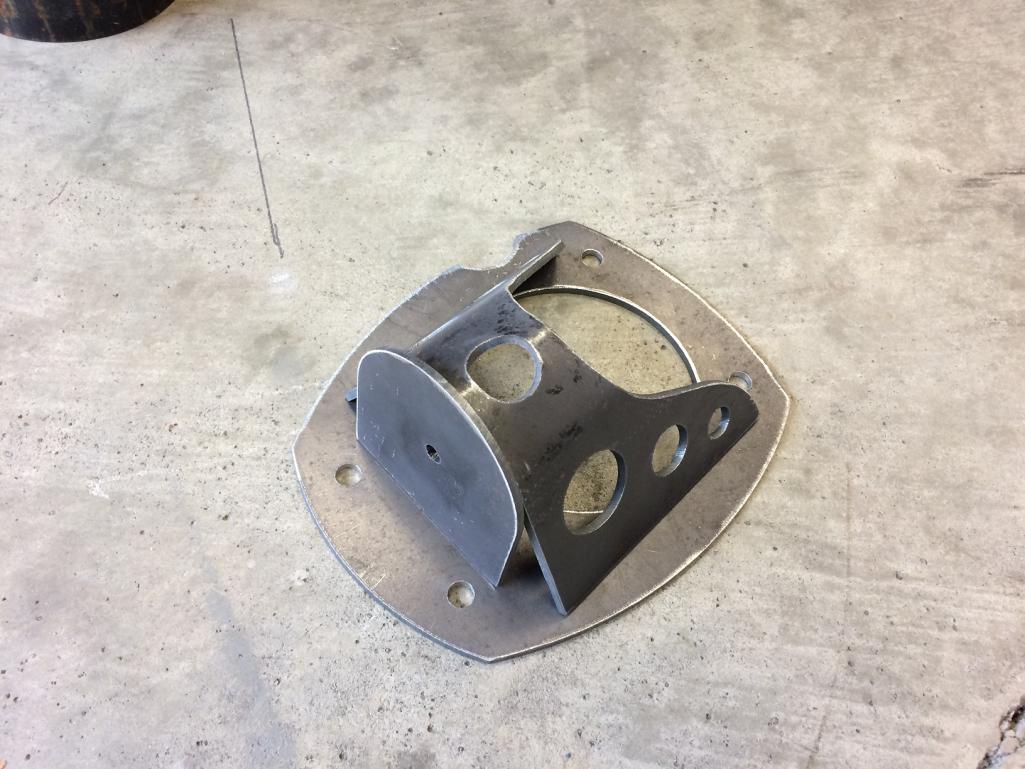 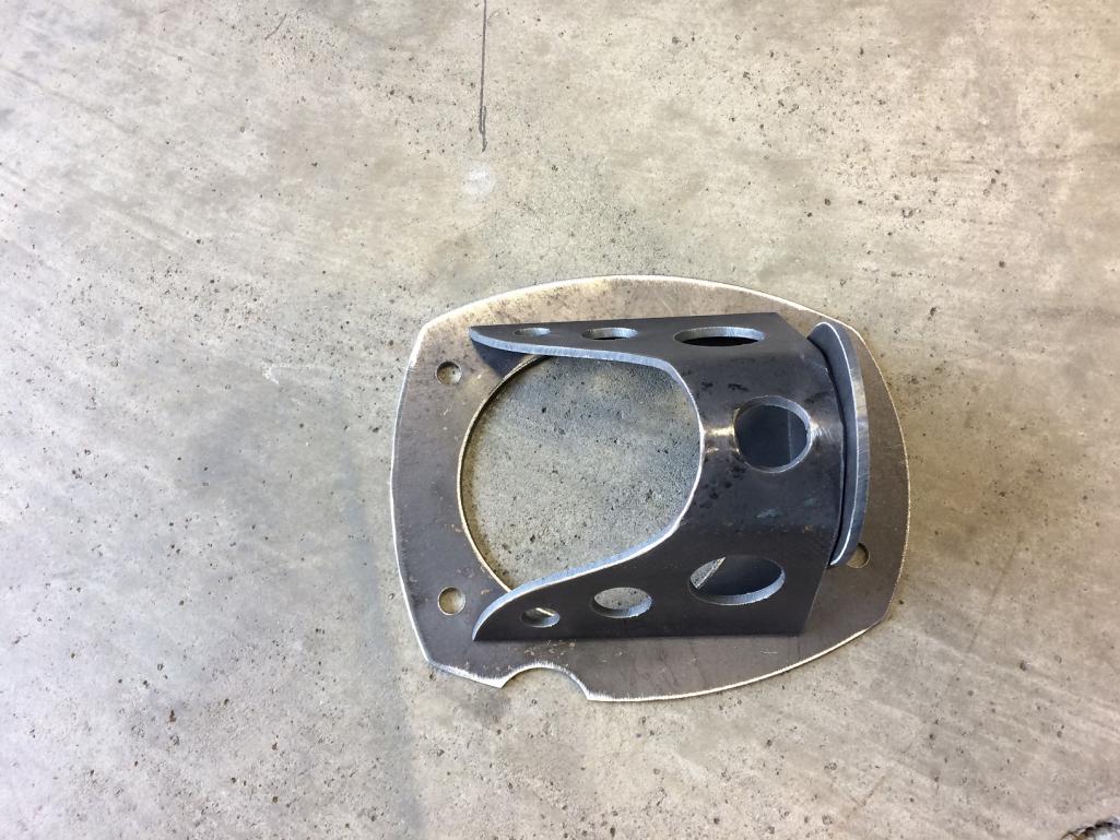
|
|
|
|
|
6 User(s) are reading this topic (6 Guests and 0 Anonymous Users)
0 Members:

|
Lo-Fi Version | Time is now: 28th April 2026 - 05:50 AM |
Invision Power Board
v9.1.4 © 2026 IPS, Inc.