|
|
|
Porsche, and the Porsche crest are registered trademarks of Dr. Ing. h.c. F. Porsche AG.
This site is not affiliated with Porsche in any way. Its only purpose is to provide an online forum for car enthusiasts. All other trademarks are property of their respective owners. |
|
|

  |

| Larmo63 |
 May 25 2020, 09:39 PM May 25 2020, 09:39 PM
Post
#2641
|
|
Advanced Member  Group: Members Posts: 4,267 Joined: 3-March 14 From: San Clemente, Ca Member No.: 17,068 Region Association: Southern California |
This whole build is just so "next level."
Really fun to watch and try to understand what exactly is going on here(?) (IMG:style_emoticons/default/smilie_pokal.gif) |
   |

 
|
| tygaboy |
May 25 2020, 10:35 PM
Post
#2642
|
|
914 Guru Group: Members Posts: 5,827 Joined: 6-October 15 From: Petaluma, CA Member No.: 19,241 Region Association: Northern California |
@djway - Here's the lift. Again, take one ATV/motorcycle lift and extend it. It works great.
Attached image(s) 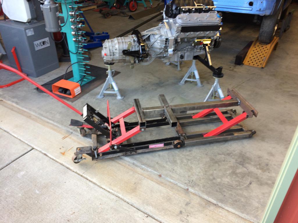
|
|
|
|
| dakotaewing |
May 25 2020, 11:17 PM
Post
#2643
|
|
Senior Member Group: Members Posts: 1,167 Joined: 8-July 03 From: DeSoto, Tx Member No.: 897 Region Association: Southwest Region |
Just curious, would those headers fit / or hit the cv/axle shafts if you ran them "under" instead of "over"?
|
|
|
|
| Krieger |
May 25 2020, 11:31 PM
Post
#2644
|
|
Advanced Member Group: Members Posts: 4,862 Joined: 24-May 04 From: Santa Rosa CA Member No.: 2,104 Region Association: None |
QUOTE(tygaboy @ May 25 2020, 09:35 PM)  Amazing Chris! |
 |
|
| djway |
May 26 2020, 01:54 AM
Post
#2645
|
|
Senior Member Group: Members Posts: 787 Joined: 16-October 15 From: Riverside Member No.: 19,266 Region Association: Southern California |
QUOTE(tygaboy @ May 25 2020, 09:35 PM) Thank you |
|
|
|
| tygaboy |
May 26 2020, 09:30 AM
Post
#2646
|
|
914 Guru Group: Members Posts: 5,827 Joined: 6-October 15 From: Petaluma, CA Member No.: 19,241 Region Association: Northern California |
QUOTE(dakotaewing @ May 25 2020, 10:17 PM) Just curious, would those headers fit / or hit the cv/axle shafts if you ran them "under" instead of "over"? @dakotaewing - No, these can't work in that orientation. They are "turbo forward" headers and yes, I screwed around to see if they would fit as you mention. They run into the block well before the flange is near seating on the head, they interfere with the starter, etc, etc. Prior to going with this style, I bought a set of stock Corvette (LS3) cast iron exhaust manifolds. Unlike the similar Camaro style, the Corvette version locates the collector in the middle vs at the end, and at a more advantageous angle, allowing more room to get the exhaust turned up to clear the axles. If I ever built a "low" exhaust, I'd use them. Attached image(s) 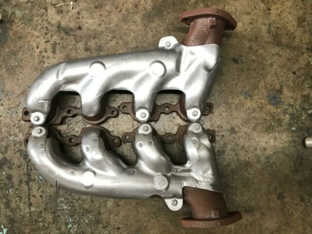 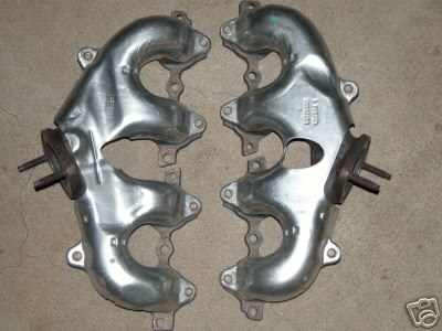
|
|
|
|
| dwillouby |
May 26 2020, 09:36 AM
Post
#2647
|
|
Member Group: Members Posts: 395 Joined: 27-December 02 From: Mt Washington, KY Member No.: 29 Region Association: None |
Hi,
I copied Chris's engine lift design. Works great. I used 06 corvette manifolds and ran over the axles. David |
|
|
|
| tygaboy |
May 26 2020, 09:37 AM
Post
#2648
|
|
914 Guru Group: Members Posts: 5,827 Joined: 6-October 15 From: Petaluma, CA Member No.: 19,241 Region Association: Northern California |
QUOTE(Larmo63 @ May 25 2020, 08:39 PM) This whole build is just so "next level." Really fun to watch and try to understand what exactly is going on here(?) (IMG:style_emoticons/default/smilie_pokal.gif) @Larmo63 - Glad to hear you're enjoying the madness. If you do figure out what's going on, please let me know! (IMG:style_emoticons/default/laugh.gif) From the beginning, this build was based on my favorite Monty Python line: https://www.youtube.com/watch?v=3Eyx_DhepDg |
|
|
|
| tygaboy |
May 26 2020, 09:41 AM
Post
#2649
|
|
914 Guru Group: Members Posts: 5,827 Joined: 6-October 15 From: Petaluma, CA Member No.: 19,241 Region Association: Northern California |
And credit where credit is due:
I copied @andys Andy's lift design. See post #9 on this page for good pics and a much tidier execution! http://www.914world.com/bbs2/index.php?sho...=204625&hl= Thanks for sharing, Andy! (IMG:style_emoticons/default/aktion035.gif) |
|
|
|
| tygaboy |
May 27 2020, 04:23 PM
Post
#2650
|
|
914 Guru Group: Members Posts: 5,827 Joined: 6-October 15 From: Petaluma, CA Member No.: 19,241 Region Association: Northern California |
During this build, I've had to start from scratch and learn a number of skills, including welding, metal forming, fabrication, CAD and CAM software, a new plasma table, etc.
Next, apparently, will be my nemesis: WIRING. The EFI engine harness that came as part of the ITB kit is designed for an "engine in front". Many/most of the pre-terminated connectors are too long or too short and much of the messy stuff is at the rear of the engine, which is the main view of it in my car. My OCD simply can't tolerate all this messy wiring. I contemplated trying to modify the kit harness but after talking with the Techs at Holley (it's a Holley HP ECU and harness), I opted to start over with an un-terminated kit. What was I thinking? (IMG:style_emoticons/default/blink.gif) Well, I figured out most of the other stuff, I'll figure this out, too. Attached thumbnail(s) 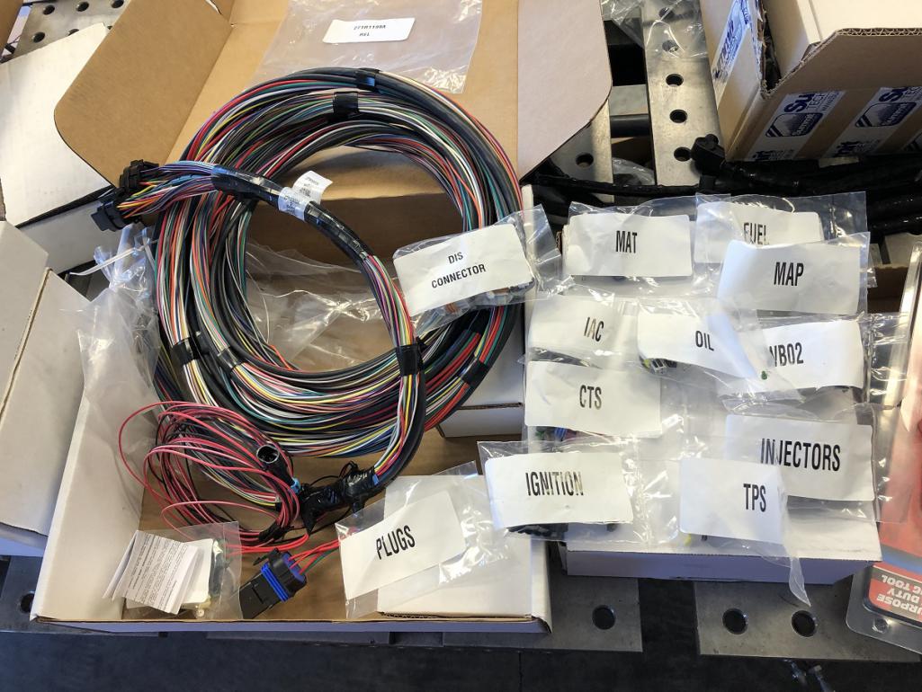
|
|
|
|
| tygaboy |
May 27 2020, 04:24 PM
Post
#2651
|
|
914 Guru Group: Members Posts: 5,827 Joined: 6-October 15 From: Petaluma, CA Member No.: 19,241 Region Association: Northern California |
This is what I found unacceptable. Anyone need an LS3/Holley HP Engine harness? (IMG:style_emoticons/default/biggrin.gif)
Attached thumbnail(s) 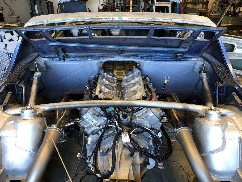
|
|
|
|
| tygaboy |
May 27 2020, 04:28 PM
Post
#2652
|
|
914 Guru Group: Members Posts: 5,827 Joined: 6-October 15 From: Petaluma, CA Member No.: 19,241 Region Association: Northern California |
I started with a mock up of routing for the injector harness. Again, the kit, as delivered, is designed for the stock LS3 intake, not ITBs, so the injector harness loom was too short in places and forced the main connector to be at the back of the engine.
This unterminated injector harness kit will allow me to hide the connector at the front. Way mo' betta! (IMG:style_emoticons/default/aktion035.gif) Attached thumbnail(s) 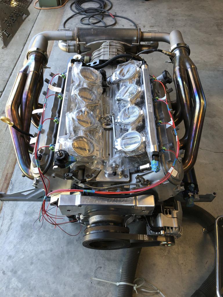
|
|
|
|
| tygaboy |
May 27 2020, 04:32 PM
Post
#2653
|
|
914 Guru Group: Members Posts: 5,827 Joined: 6-October 15 From: Petaluma, CA Member No.: 19,241 Region Association: Northern California |
I finished the day by completing the plug wires. All nice and hidden from view.
In the end, I'm trying for the "no wires visible" look across the entire engine. I'll likely have a few but it'll be far cleaner than what it was and should look pretty tidy. Attached thumbnail(s) 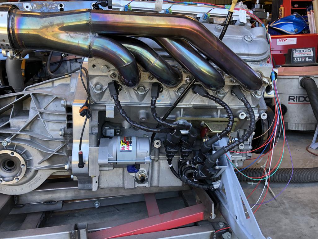 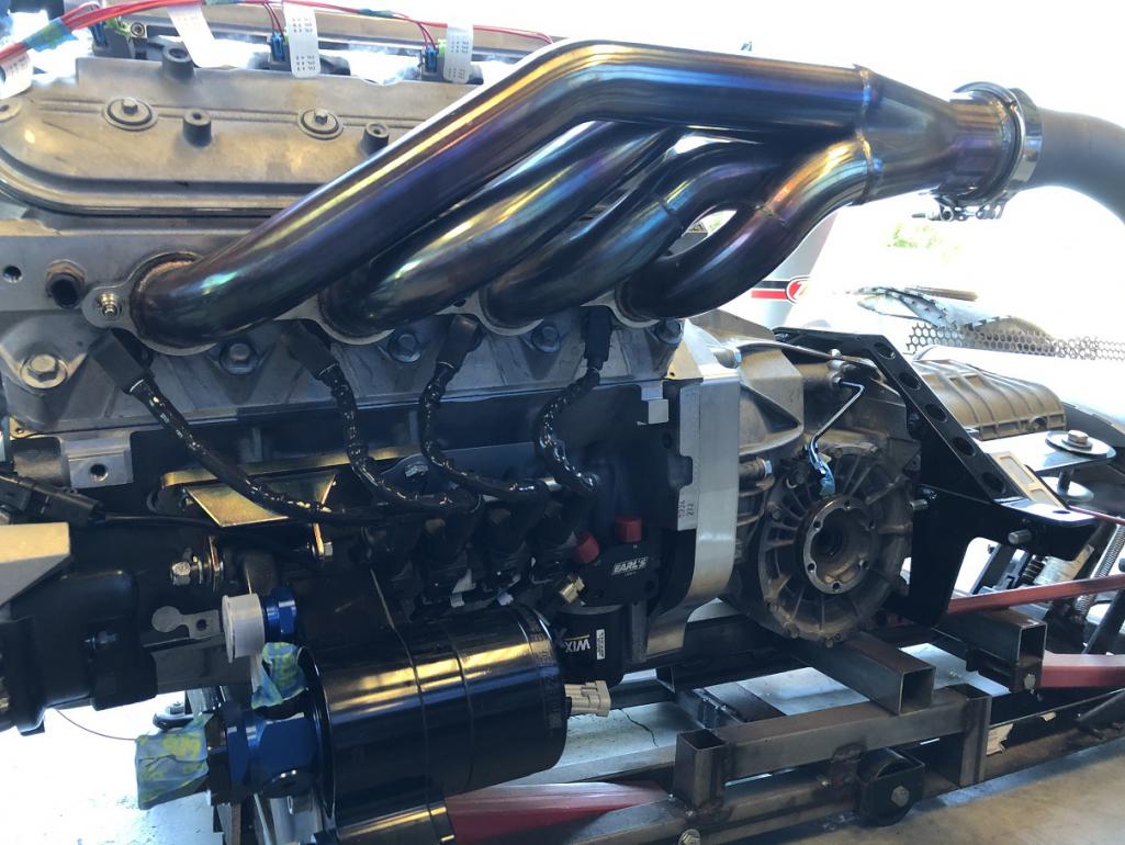
|
|
|
|
| djway |
May 27 2020, 04:35 PM
Post
#2654
|
|
Senior Member Group: Members Posts: 787 Joined: 16-October 15 From: Riverside Member No.: 19,266 Region Association: Southern California |
With all the fancy cool tools you have you possibly could fab up some wiring covers that attached to the engine hide the wires and add even more I candy. Just a thought.
|
|
|
|
| Cairo94507 |
May 28 2020, 06:11 AM
Post
#2655
|
|
Michael Group: Members Posts: 10,671 Joined: 1-November 08 From: Auburn, CA Member No.: 9,712 Region Association: Northern California |
Man, that is looking pretty. Of course the wiring was going to be next level stuff. (IMG:style_emoticons/default/beerchug.gif)
|
|
|
|
| Andyrew |
May 28 2020, 07:27 AM
Post
#2656
|
|
Spooling.... Please wait Group: Members Posts: 13,380 Joined: 20-January 03 From: Riverbank, Ca Member No.: 172 Region Association: Northern California |
Wow! Next level stuff for sure!
Are the wires long enough that you wont have to join any wires? I suspect that you'll add plugs as needed and pin wires? Im just curious if you've subscribed to the solder vs crimp method for wire connection. |
|
|
|
| tygaboy |
May 28 2020, 08:18 AM
Post
#2657
|
|
914 Guru Group: Members Posts: 5,827 Joined: 6-October 15 From: Petaluma, CA Member No.: 19,241 Region Association: Northern California |
QUOTE(Andyrew @ May 28 2020, 06:27 AM) Wow! Next level stuff for sure! Are the wires long enough that you wont have to join any wires? I suspect that you'll add plugs as needed and pin wires? Im just curious if you've subscribed to the solder vs crimp method for wire connection. @Andyrew Andrew - Yep, all the wires are plenty long so it's a simple matter (IMG:style_emoticons/default/laugh.gif) of determining the physical layout then pinning the wires for each connector. There are some wires that need to be joined. For example, the red power leads in the injector harness get joined/soldered along the run so they terminate in a single wire at the harness connector. All the connectors and associated pins/seal are provided with the various wiring kits I'm using and are either metri pack, Weather Pack or Deutsch. I have all the appropriate crimpers/jaws and de-pinning tools needed to assemble them. No soldering on any of those connectors. Deutsch even calls out soldering isn't recommended. I'll take their guidance. |
|
|
|
| mbseto |
May 28 2020, 08:53 AM
Post
#2658
|
|
Senior Member Group: Members Posts: 1,257 Joined: 6-August 14 From: Cincy Member No.: 17,743 Region Association: North East States |
"...being old and safety minded, I politely declined..."
Goes back to cramming LS3 into go-cart. |
|
|
|
| Andyrew |
May 28 2020, 12:38 PM
Post
#2659
|
|
Spooling.... Please wait Group: Members Posts: 13,380 Joined: 20-January 03 From: Riverbank, Ca Member No.: 172 Region Association: Northern California |
QUOTE(tygaboy @ May 28 2020, 07:18 AM) QUOTE(Andyrew @ May 28 2020, 06:27 AM) Wow! Next level stuff for sure! Are the wires long enough that you wont have to join any wires? I suspect that you'll add plugs as needed and pin wires? Im just curious if you've subscribed to the solder vs crimp method for wire connection. @Andyrew Andrew - Yep, all the wires are plenty long so it's a simple matter (IMG:style_emoticons/default/laugh.gif) of determining the physical layout then pinning the wires for each connector. There are some wires that need to be joined. For example, the red power leads in the injector harness get joined/soldered along the run so they terminate in a single wire at the harness connector. All the connectors and associated pins/seal are provided with the various wiring kits I'm using and are either metri pack, Weather Pack or Deutsch. I have all the appropriate crimpers/jaws and de-pinning tools needed to assemble them. No soldering on any of those connectors. Deutsch even calls out soldering isn't recommended. I'll take their guidance. So long as the crimp is good I agree without soldering. I soldered most of mine and then I FILLED it with super glue so that it wouldnt move, and then finished it up with the shrink wrap and wire sleave. I will say thats going to be a TON of pinning... That pinning and depinning tool will pay for themselves in stress.. I will say Depinning for me is a PITA. I can never get it right.. |
|
|
|
| tygaboy |
May 28 2020, 05:39 PM
Post
#2660
|
|
914 Guru Group: Members Posts: 5,827 Joined: 6-October 15 From: Petaluma, CA Member No.: 19,241 Region Association: Northern California |
@Andyrew - This is my first go with wiring and I did end up purchasing all the needed crimpers and de-pinning tools. After the first couple, everything went fine. I'm assuming you have the correct tool for the connectors?
I ended up having to get 4 different de-pinners to work with the various types of connectors I have across the different harnesses. But as a tool whore, I'm OK with that! Anyway, here's my crimp vs what the instructions say it should look like. Let me just say: There is absolutely nothing like having the right tools for the job! Attached thumbnail(s) 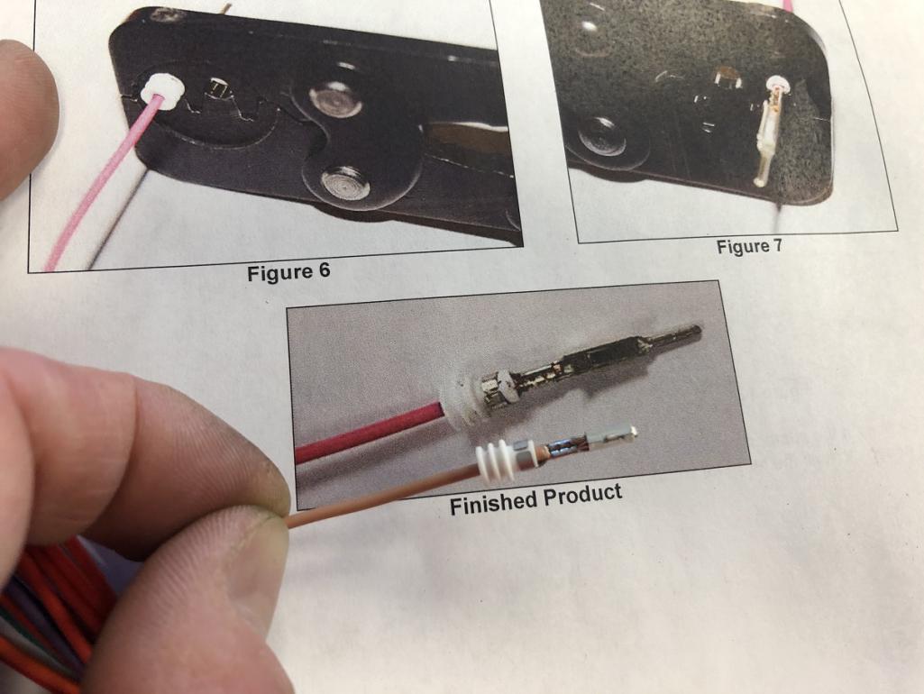
|
|
|
|
|
1 User(s) are reading this topic (1 Guests and 0 Anonymous Users)
0 Members:

|
Lo-Fi Version | Time is now: 15th June 2026 - 11:04 PM |
Invision Power Board
v9.1.4 © 2026 IPS, Inc.