|
|
|
Porsche, and the Porsche crest are registered trademarks of Dr. Ing. h.c. F. Porsche AG.
This site is not affiliated with Porsche in any way. Its only purpose is to provide an online forum for car enthusiasts. All other trademarks are property of their respective owners. |
|
|

  |

| Dion |
 Feb 9 2022, 07:22 AM Feb 9 2022, 07:22 AM
Post
#3901
|
|
RN  Group: Members Posts: 2,931 Joined: 16-September 04 From: Shepherdstown, WV Member No.: 2,766 Region Association: MidAtlantic Region |
That there is phenomenal work on that wiring harness. Talk about perseverance.
Well done. I may have missed it but did you “chart” it all out schematic wise to trouble shoot in the future? Like in a computer program or old fashioned written down? I imagine some of the components your using have their own diagrams. Just curious. |
   |

 
|
| tygaboy |
Feb 9 2022, 09:39 AM
Post
#3902
|
|
914 Guru Group: Members Posts: 5,844 Joined: 6-October 15 From: Petaluma, CA Member No.: 19,241 Region Association: Northern California |
@Dion - I'm not sure how far I'll take the documentation. For assembly and trouble-shooting this part of the harness, I really only need the pin map that I'm working up here. It's not yet complete but you get the idea.
I'll post details as I build the engine side of the harness. The cool thing about that is the harness branch to each sensor will be individually labelled so it's sorta "diagrammed in the real world". (Pic of the printed heat shrink for your enjoyment.) I got some printable heat shrink sleeves for my label maker so I'll likely go overboard and do the same for each branch of the car's chassis harness, too. I mean, who wouldn't want to be absolutely sure that wire that looks like it goes to the horn, ACTUALLY goes to the horn? (IMG:style_emoticons/default/lol-2.gif) No kill like overkill, eh? (IMG:style_emoticons/default/shades.gif) Attached thumbnail(s) 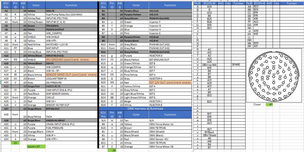 Attached image(s) 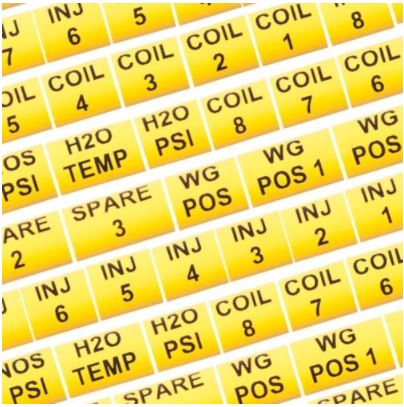
|
|
|
|
| tygaboy |
Feb 9 2022, 09:42 AM
Post
#3903
|
|
914 Guru Group: Members Posts: 5,844 Joined: 6-October 15 From: Petaluma, CA Member No.: 19,241 Region Association: Northern California |
QUOTE(Cairo94507 @ Feb 9 2022, 05:06 AM)  Great looking seat! If I was 30 years younger I would put them in my car. (IMG:style_emoticons/default/beerchug.gif) @Cairo94507 - Michael - Thanks for your earlier compliments. And these seats aren't too bad. Next time our cars are together, you're welcome to swap one in and give it a go. |
|
|
|
| tygaboy |
Feb 9 2022, 09:58 AM
Post
#3904
|
|
914 Guru Group: Members Posts: 5,844 Joined: 6-October 15 From: Petaluma, CA Member No.: 19,241 Region Association: Northern California |
Re: my comment about lessons learned:
This morning I got a helpful PM from @superhawk996 cautioning me about the use of those solder sleeves. Phil, who has experience with stuff like this that's well beyond mine, pointed out what I had already experienced - that they require a deft touch when heating to ensure the solder flows out completely without overheating stuff near it. As I mentioned in my reply to him, while I think I got it right, and the testing was successful, I'm "fingers crossed" that I have a reliable connection. In any case, after installing three of them, I went back to the open barrel crimps. What if I have an issue? Well, you know me! I'll call it "practice" and do it over! (IMG:style_emoticons/default/av-943.gif) Big thanks to Phil for his input. Just another example of the great folks in this community. |
|
|
|
| Superhawk996 |
Feb 9 2022, 12:27 PM
Post
#3905
|
|
914 Guru Group: Members Posts: 7,959 Joined: 25-August 18 From: Woods of N. Idaho Member No.: 22,428 Region Association: Galt's Gulch |
Per discussion with Chris I'll repost my PM with him so that others are more fully aware of the downside to those heat shrink solder butt connectors:
I have a bunch of experience with those heat shrink solder connectors both in motorsports and DoD defense applications. Bottom line, they are highly variable. If done EXACTLY right they work fine. What I've found is that they are only done right about 5% of the time (as used by DoD field service reps - i.e. former military maintenace guys). There is no good way to control the heat applied and/or to assure that the solder has properly tinned out and flowed INTO the the stranded wires rather than just forming a cold solder joint ring around the butt ends on the exterior of the stranding. I then recommended that Chris mark the harness location of the solder connectors for easy future reference while he still remembers where they are. I've had numerous experiences tearing apart wiring harnesses that had issues with intermittent grounds and grounded shields where those heat shrink solder connectors failed. Not fun. Even less fun if you don't know exactly where the splice was placed. Overall beautiful harness work and Chris is stepping up the game for the rest of us. I was just reluctant to post here publicly as I didn't want to appear be tearing down the great work he's doing. |
|
|
|
| tygaboy |
Feb 9 2022, 04:45 PM
Post
#3906
|
|
914 Guru Group: Members Posts: 5,844 Joined: 6-October 15 From: Petaluma, CA Member No.: 19,241 Region Association: Northern California |
Time for the engine side of the bulkhead. This will be easier in that the wires will run straight out of the connector - no 90 degree bend - so the wires can all be cut to the same length. Plus, I can make any final length adjustments at the sensor end so this should turn out even nicer than the first side. Wish me luck!
Attached thumbnail(s) 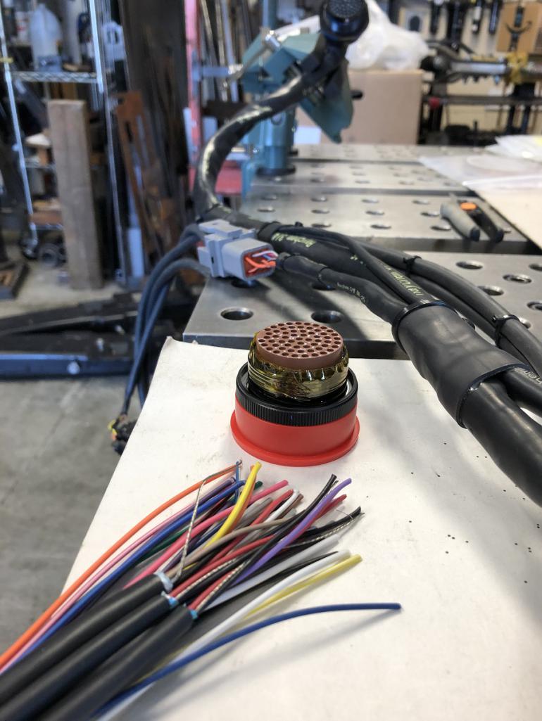
|
|
|
|
| tygaboy |
Feb 9 2022, 04:47 PM
Post
#3907
|
|
914 Guru Group: Members Posts: 5,844 Joined: 6-October 15 From: Petaluma, CA Member No.: 19,241 Region Association: Northern California |
And another nod to @Superhawk996 Phil. Open barrel crimps, baby! (IMG:style_emoticons/default/aktion035.gif) That's where it's at from here on...
Attached thumbnail(s) 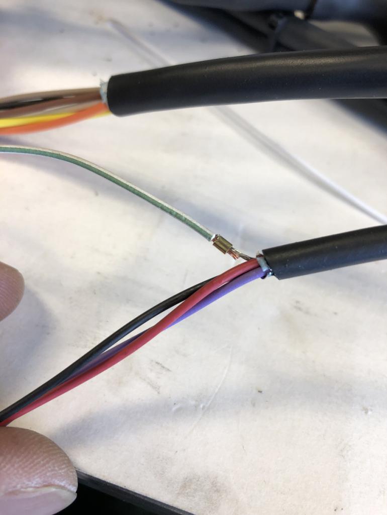
|
|
|
|
| tygaboy |
Feb 9 2022, 04:50 PM
Post
#3908
|
|
914 Guru Group: Members Posts: 5,844 Joined: 6-October 15 From: Petaluma, CA Member No.: 19,241 Region Association: Northern California |
All the open barrel crimps have been sealed with heat shrink. All the engine side wires are pinned and ready to be installed in the connector.
Attached thumbnail(s) 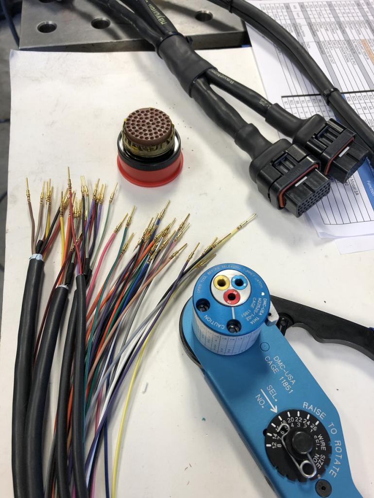
|
|
|
|
| Superhawk996 |
Feb 9 2022, 05:01 PM
Post
#3909
|
|
914 Guru Group: Members Posts: 7,959 Joined: 25-August 18 From: Woods of N. Idaho Member No.: 22,428 Region Association: Galt's Gulch |
QUOTE(tygaboy @ Feb 9 2022, 05:47 PM) Open barrel crimps, baby! (IMG:style_emoticons/default/aktion035.gif) That's where it's at from here on... (IMG:style_emoticons/default/smilie_pokal.gif) I think you'll find that if you stagger them and orient them flat side down, they really aren't any more bulky than the solder butt connectors. You truly are upping the game - keep up the inspiration for the rest of us. |
|
|
|
| tygaboy |
Feb 9 2022, 07:14 PM
Post
#3910
|
|
914 Guru Group: Members Posts: 5,844 Joined: 6-October 15 From: Petaluma, CA Member No.: 19,241 Region Association: Northern California |
QUOTE(Superhawk996 @ Feb 9 2022, 03:01 PM) QUOTE(tygaboy @ Feb 9 2022, 05:47 PM) Open barrel crimps, baby! (IMG:style_emoticons/default/aktion035.gif) That's where it's at from here on... (IMG:style_emoticons/default/smilie_pokal.gif) I think you'll find that if you stagger them and orient them flat side down, they really aren't any more bulky than the solder butt connectors. You truly are upping the game - keep up the inspiration for the rest of us. @superhawk996 Phil - Yep, agree. I used the smallest open barrel crimp I had and they're pretty tiny. Even with the heat shrink, there'll be no issue with space. And I do try and stagger them. Thanks for your input and the kind words. I gotta say, this level of work really isn't that different from "regular old" wiring. Yes, the components and tools are more $, but seriously, ANYONE could do this. I'm no more talented or capable than the rest of you. I think I'll have t-shirts made that say "Try New Stuff!" |
|
|
|
| tygaboy |
Feb 9 2022, 07:35 PM
Post
#3911
|
|
914 Guru Group: Members Posts: 5,844 Joined: 6-October 15 From: Petaluma, CA Member No.: 19,241 Region Association: Northern California |
And again, if you don't find yourself bored enough by pictures and text about wiring, here's a video that'll surely put you to sleep! (IMG:style_emoticons/default/lol-2.gif) But hey, maybe some of you will find it interesting. If nothing else, it's a glimpse into how I've been spending my time.
https://www.youtube.com/watch?v=S5SpTL-Vcaw |
|
|
|
| Cairo94507 |
Feb 10 2022, 08:40 AM
Post
#3912
|
|
Michael Group: Members Posts: 10,716 Joined: 1-November 08 From: Auburn, CA Member No.: 9,712 Region Association: Northern California |
That is a super nice way to make connections. Very clean job and I am pretty darn sure you will not have connection issues with the care you are taking. (IMG:style_emoticons/default/beerchug.gif)
|
|
|
|
| Dion |
Feb 10 2022, 08:10 PM
Post
#3913
|
|
RN Group: Members Posts: 2,931 Joined: 16-September 04 From: Shepherdstown, WV Member No.: 2,766 Region Association: MidAtlantic Region |
Thanks for the info Chris. Fascinating stuff. You have quite the arsenal of wiring tools now. Thanks for the vid too.
I would never have thought this kind of stuff would be available to the DIY . Keep at it mate. Enjoying the teaching. (IMG:style_emoticons/default/beerchug.gif) |
|
|
|
| willieg |
Feb 11 2022, 09:23 AM
Post
#3914
|
|
Member Group: Members Posts: 147 Joined: 13-August 18 From: Pleasant Hill Member No.: 22,389 Region Association: Northern California |
QUOTE(tygaboy @ Feb 4 2022, 08:08 PM) So I sourced what's called a "backshell" that fits quite snugly over the back of each connector and provides a lip for heat shrink boots. These connectors are now all but sealed and the wires are fully strain relieved and far more protected. Way mo' betta. (IMG:style_emoticons/default/aktion035.gif) “backshell”….working in the garage I have learned a lot of new words. |
|
|
|
| tygaboy |
Feb 11 2022, 08:46 PM
Post
#3915
|
|
914 Guru Group: Members Posts: 5,844 Joined: 6-October 15 From: Petaluma, CA Member No.: 19,241 Region Association: Northern California |
A couple minutes on what I'm learning to do in terms of assembling these motorsport-y connectors. It's quite a time suck, especially with all the double/triple/quadruple checking I'm doing to be sure I got things right. In spite of that, I still managed to make an error in one of the connector positions. The conductor was supposed to go in the (lower case) r position and I inserted it into the (upper case) R position... (IMG:style_emoticons/default/dry.gif)
But caught it in testing and, thankfully, it's easy enough to correct things like this. (IMG:style_emoticons/default/cheer.gif) Speaking of testing, you can see that I opted to install a few wires, "connect the connector" and test the complete circuit (from ECU pin, through the connector, to the end of the conductor), record that those circuits worked, then install the next few wires. And relax, the video only shows me installing and testing a few wires, not all of them! Anyway, here you go. https://www.youtube.com/watch?v=wJIhX84i26w |
|
|
|
| tygaboy |
Feb 11 2022, 08:59 PM
Post
#3916
|
|
914 Guru Group: Members Posts: 5,844 Joined: 6-October 15 From: Petaluma, CA Member No.: 19,241 Region Association: Northern California |
Here's all the
I should have this side of the connector done on Sunday. Then routing/cutting each sensor lead to length can begin. With a bit of luck, I'll be looking to fire the engine and get back on the road in a week or so! (IMG:style_emoticons/default/driving.gif) Attached thumbnail(s) 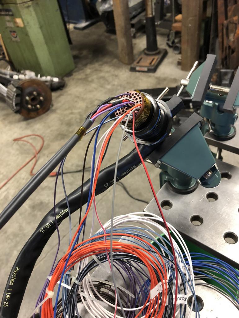
|
|
|
|
| tygaboy |
Feb 13 2022, 06:56 PM
Post
#3917
|
|
914 Guru Group: Members Posts: 5,844 Joined: 6-October 15 From: Petaluma, CA Member No.: 19,241 Region Association: Northern California |
Major milestone: All engine-side wires are pinned! (IMG:style_emoticons/default/cheer.gif)
Still a bunch of stuff to do but this part is done. The video provides a quick demo of the connector in action. Not rocket science but I think it's pretty cool. Enjoy! (IMG:style_emoticons/default/beerchug.gif) https://www.youtube.com/watch?v=JKTtYNKAntM |
|
|
|
| mikey63 |
Feb 14 2022, 09:39 AM
Post
#3918
|
|
Member Group: Members Posts: 133 Joined: 30-March 10 From: Windsor,Ca Member No.: 11,529 Region Association: Northern California |
Nice work Chris!
|
|
|
|
| Cairo94507 |
Feb 15 2022, 08:13 AM
Post
#3919
|
|
Michael Group: Members Posts: 10,716 Joined: 1-November 08 From: Auburn, CA Member No.: 9,712 Region Association: Northern California |
A very satisfying "click". (IMG:style_emoticons/default/beerchug.gif)
|
|
|
|
| tygaboy |
Feb 15 2022, 03:43 PM
Post
#3920
|
|
914 Guru Group: Members Posts: 5,844 Joined: 6-October 15 From: Petaluma, CA Member No.: 19,241 Region Association: Northern California |
This wiring stuff is way far away from "useful 914 content" so thanks for tolerating this part of my build. Given the content I've posted lately, I think I have a future in consulting on how to drive viewers AWAY from their social media outlets! (IMG:style_emoticons/default/laugh.gif) I know this may not be everyone's cup o' tea, but hopefully some find it interesting. Anyway, back to it:
Today was "Fun with DYMO!" I started labeling the harness, because overkill. You can get printable heat shrink sleeve in various widths. I used 3/4" for the large, multi conductor cables - in this case, the one that runs to the throttle body. No, it's not like it's hard to figure out that this cable runs to that location. It's more the vibe of the build and it keeps with the "race rod" theme I happen to like. Plus, it's fun! Note that I still have to source and install the clear heat shrink that gets installed over this to protect it. Attached image(s) 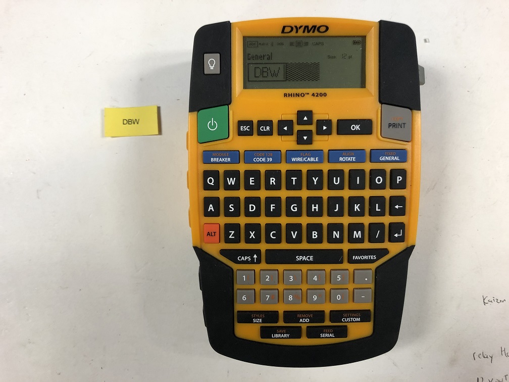 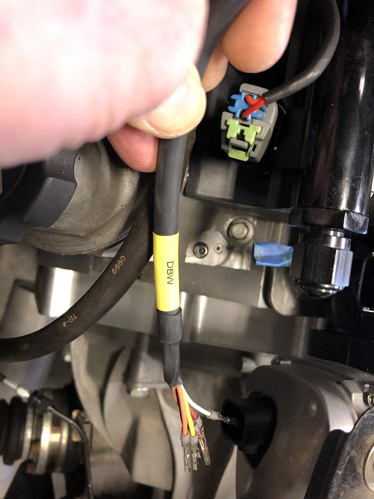
|
|
|
|
|
4 User(s) are reading this topic (4 Guests and 0 Anonymous Users)
0 Members:

|
Lo-Fi Version | Time is now: 20th July 2026 - 07:49 PM |
Invision Power Board
v9.1.4 © 2026 IPS, Inc.