|
|
|
Porsche, and the Porsche crest are registered trademarks of Dr. Ing. h.c. F. Porsche AG.
This site is not affiliated with Porsche in any way. Its only purpose is to provide an online forum for car enthusiasts. All other trademarks are property of their respective owners. |
|
|

  |

| tygaboy |
 Oct 12 2017, 06:13 PM Oct 12 2017, 06:13 PM
Post
#661
|
|
914 Guru  Group: Members Posts: 5,818 Joined: 6-October 15 From: Petaluma, CA Member No.: 19,241 Region Association: Northern California |
Then I got started on the MadDog Motorsports front sway bar stiffening plate install.
I removed the brake hose tab and all the factory paint/undercoat. Exciting, I know... Next, it's mock it all up and drill the holes for the sway bar/mounting plate. Attached thumbnail(s) 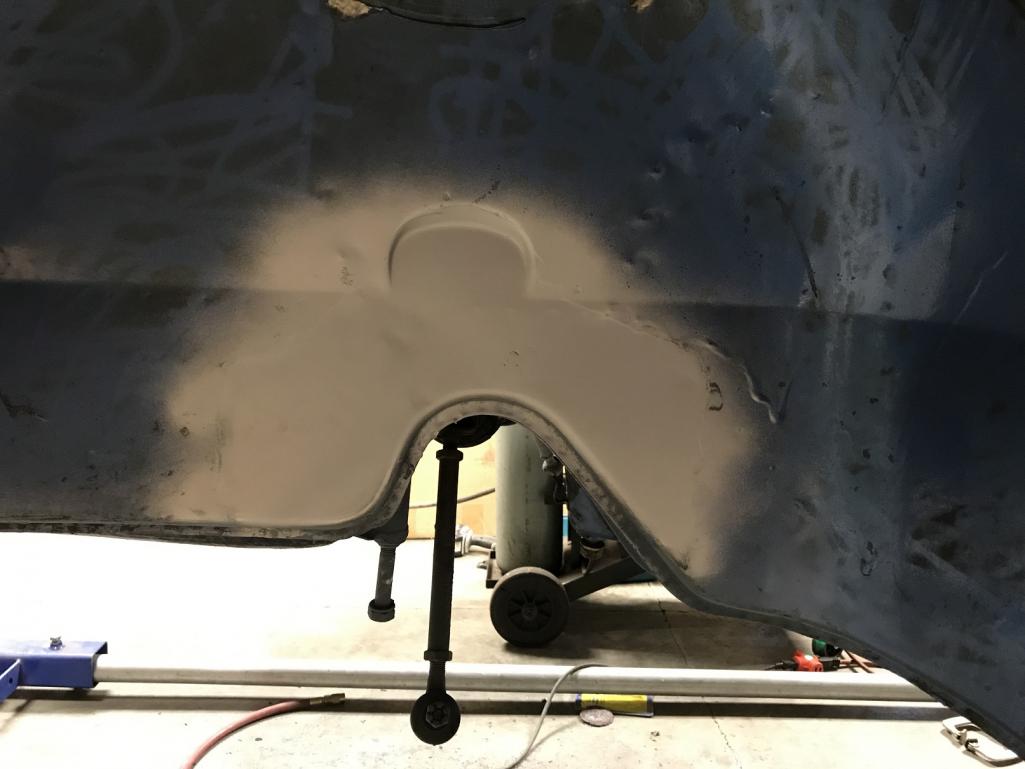
|
   |

 
|
| 914forme |
Oct 12 2017, 06:51 PM
Post
#662
|
|
Times a wastin', get wrenchin'! Group: Members Posts: 3,899 Joined: 24-July 04 From: Dayton, Ohio Member No.: 2,388 Region Association: None |
Just weld the plate on and use it as your guide. (IMG:style_emoticons/default/confused24.gif) BTW, I still add a nut plate to the back side.
Do yourself a huge favor unless your box section is cut and don't do it. Brad's Kit is so nice, I will never cut another 914 box section again. Since you have the MadDogg mount, just weld a nut to the lower bolt hole. Then make a bracket with two nuts for the top, and weld them inside. In reality you most likely could just weld all three mounting holes with a nut on the back side, drill your holes and weld it on. I love to weld, so I'll go with the welding sandwich (IMG:style_emoticons/default/av-943.gif) (IMG:style_emoticons/default/welder.gif) |
|
|
|
| tygaboy |
Oct 12 2017, 07:15 PM
Post
#663
|
|
914 Guru Group: Members Posts: 5,818 Joined: 6-October 15 From: Petaluma, CA Member No.: 19,241 Region Association: Northern California |
Stephen -
Yep, I used Brad's kit on my '74 and it was really nice.I have the MadDog triangle mount with the nuts welded on all three corners. I was going to cut it down to make it like Brad's. Easy peasy, as they say. |
|
|
|
| tygaboy |
Oct 13 2017, 12:44 PM
Post
#664
|
|
914 Guru Group: Members Posts: 5,818 Joined: 6-October 15 From: Petaluma, CA Member No.: 19,241 Region Association: Northern California |
Before I try and button up things like that gap in the rear floor/jack triangle, I need to be sure all other "major" stuff is in place.
Today, it's establishing the relocated seat belt retractor mounts. These have to be moved due to where I routed the upper portion of the door bars. And again, more fun due to the custom lower firewall: In order to function correctly, the seat belt retractor mechanism MUST sit exactly upright. Well, my fancy fire wall isn't straight up and down. I moved the lower cross bar forward to be sure I had plenty of clearance for the engine damper. So, a bit of notching here, a but of fitting there and the passenger side is mocked in. Hard to tell from that first pic but the other support really does lean back. I still have to fab a threaded boss for the retractor to bolt to. I'm thinking it'll be a blind tapped boss that's plug welded from the back side of this brace then welded all around the front side. The good news is the fact that the retractor is recessed into the firewall. This means there's room for the seats to slide back. Best of all, the chrome belt guide that mounts behind the retractor comes forward just the right amount that the belt nicely clears the upper fire wall cross bar! I love it when a plan comes together. (IMG:style_emoticons/default/shades.gif) Attached thumbnail(s) 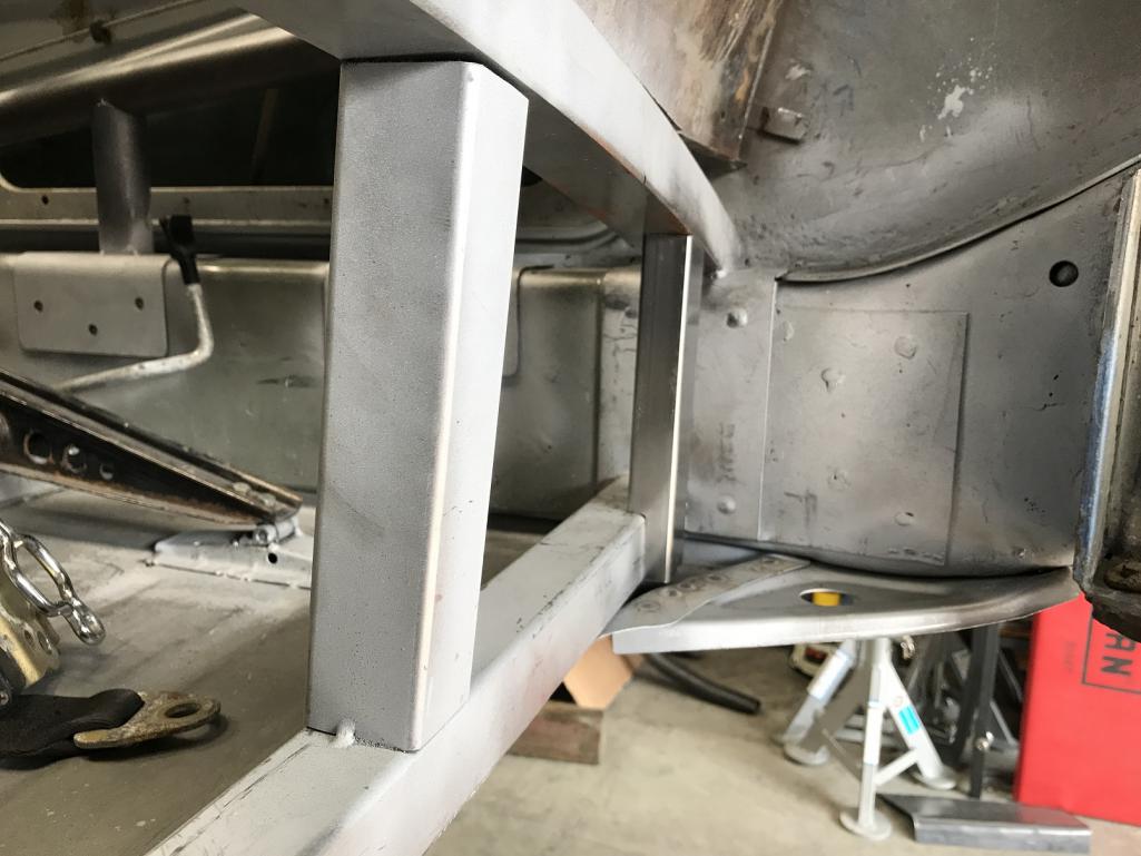 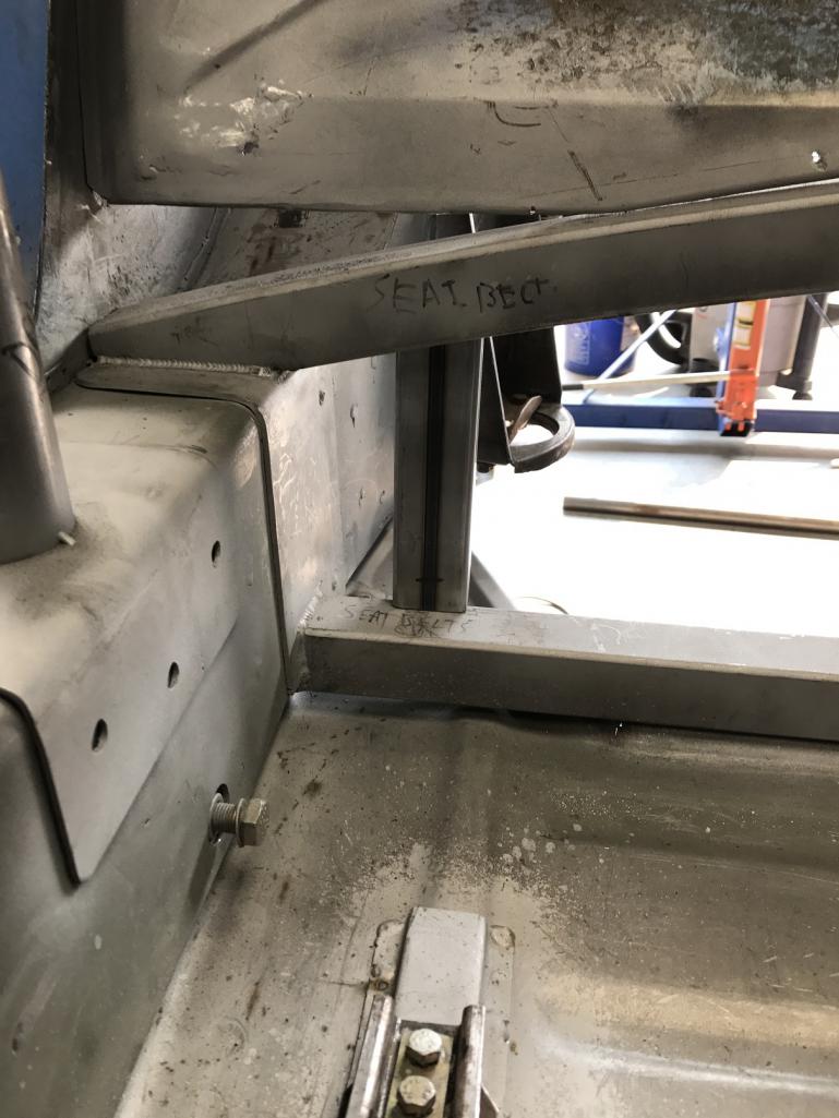
|
|
|
|
| tygaboy |
Oct 13 2017, 03:40 PM
Post
#665
|
|
914 Guru Group: Members Posts: 5,818 Joined: 6-October 15 From: Petaluma, CA Member No.: 19,241 Region Association: Northern California |
Completed the driver side mock up.
I'll do the threaded bung work on the bench then install these supports in the chassis. While I was at it, I finished up the rosette welding on those door bar verticals' support pads. Just didn't get a pic of that today. Attached thumbnail(s) 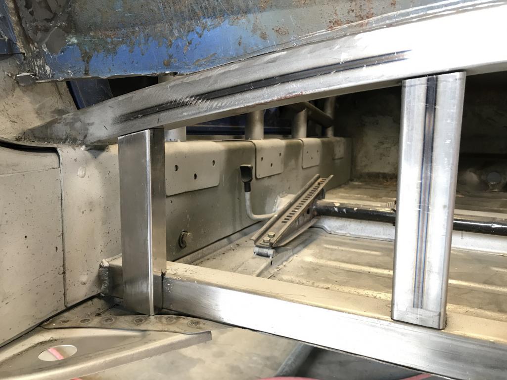 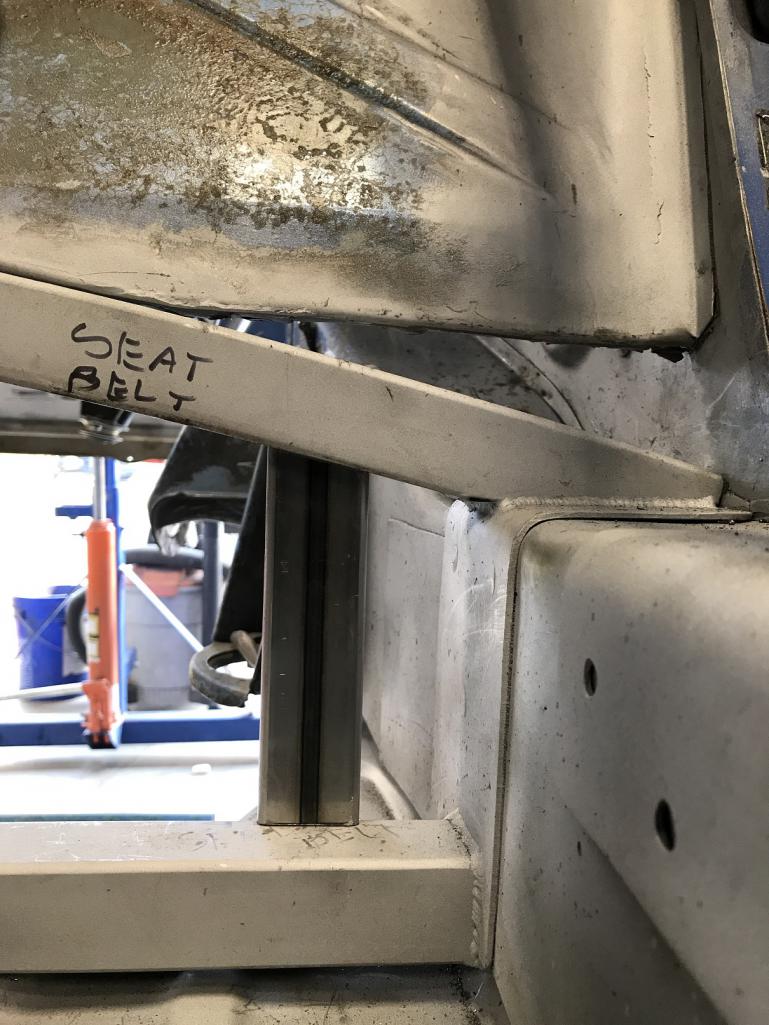
|
|
|
|
| tygaboy |
Oct 14 2017, 03:46 PM
Post
#666
|
|
914 Guru Group: Members Posts: 5,818 Joined: 6-October 15 From: Petaluma, CA Member No.: 19,241 Region Association: Northern California |
Back to installing the front sway bar mounting points. I went with the Elephant Racing bladed adjustable sway bar. It's big - just under 1.5" OD. That's the Elephant backing plate along side the MadDog reinforcement plate.
Nothing the 1.5" hole saw can't handle. (IMG:style_emoticons/default/sawzall-smiley.gif) Attached thumbnail(s) 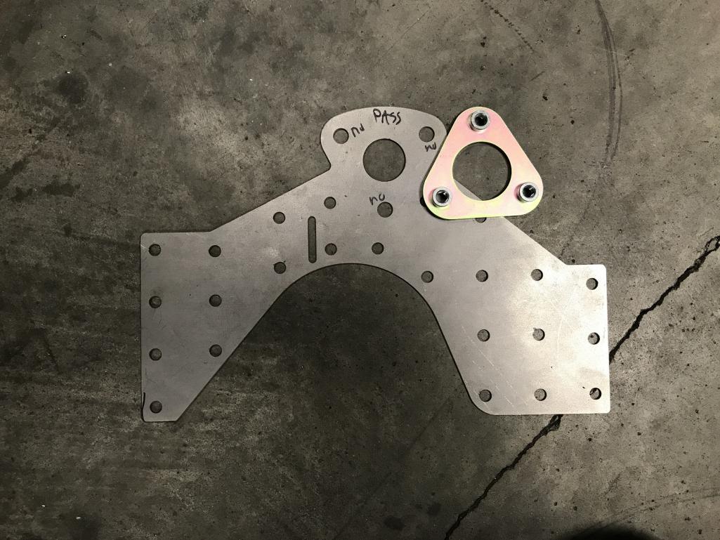
|
|
|
|
| tygaboy |
Oct 14 2017, 05:31 PM
Post
#667
|
|
914 Guru Group: Members Posts: 5,818 Joined: 6-October 15 From: Petaluma, CA Member No.: 19,241 Region Association: Northern California |
That really is a big hole. I'd say anyone thinking of going with this sway bar really should add the MadDog sway bar reinforcement kit.
And I hogged out the lower hole to account for the welded-on-bolt approach vs cutting the inner sheet metal. Attached thumbnail(s) 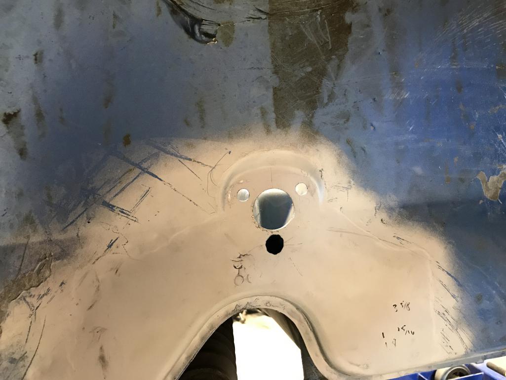
|
|
|
|
| tygaboy |
Oct 14 2017, 05:45 PM
Post
#668
|
|
914 Guru Group: Members Posts: 5,818 Joined: 6-October 15 From: Petaluma, CA Member No.: 19,241 Region Association: Northern California |
Modified passenger reinforcement plate with 1.5" hole and welded on lower nut vs standard.
Attached thumbnail(s) 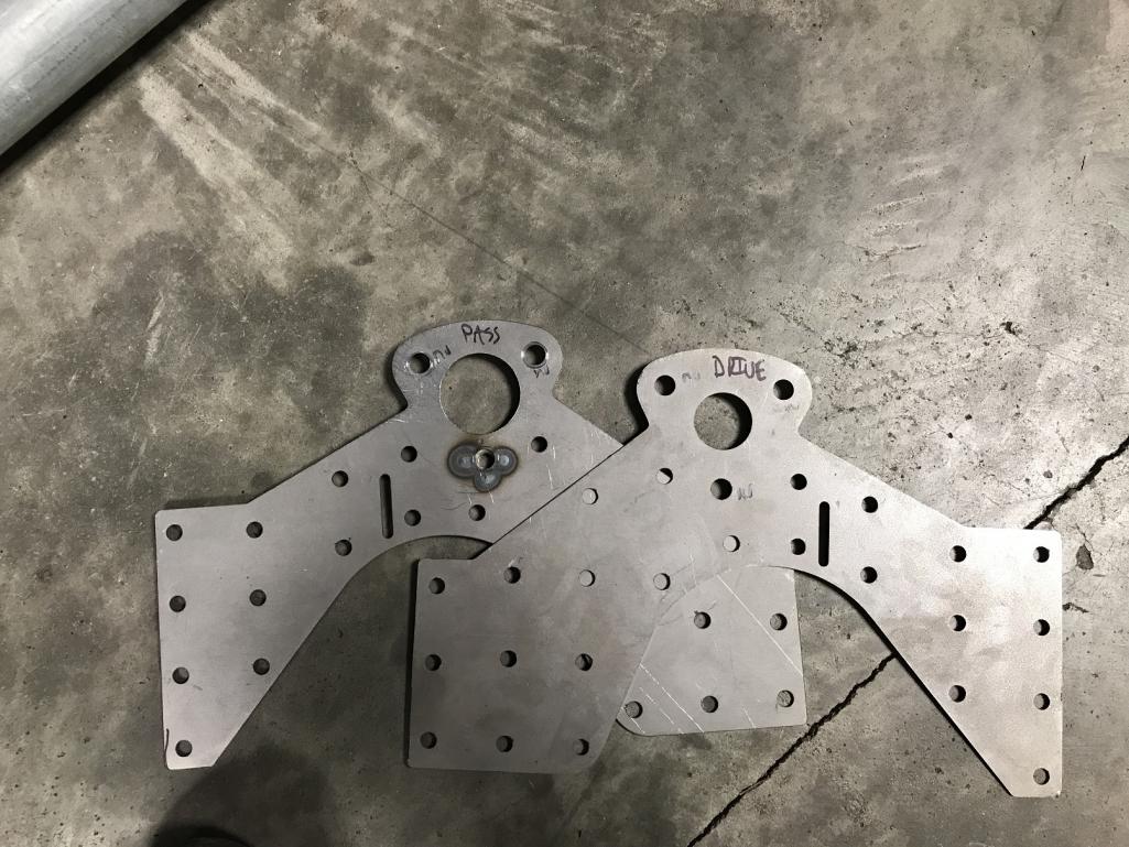
|
|
|
|
| Morph914 |
Oct 14 2017, 09:06 PM
Post
#669
|
|
Member Group: Members Posts: 435 Joined: 22-August 16 From: St Augustine, FL Member No.: 20,326 Region Association: South East States |
QUOTE(tygaboy @ Oct 14 2017, 05:45 PM)  Modified passenger reinforcement plate with 1.5" hole and welded on lower nut vs standard. Hey Chris, keep up the good work! (IMG:style_emoticons/default/pray.gif) I hope you're safe from all the fires out there. |
|
|
|
| Andyrew |
Oct 15 2017, 01:26 AM
Post
#670
|
|
Spooling.... Please wait Group: Members Posts: 13,380 Joined: 20-January 03 From: Riverbank, Ca Member No.: 172 Region Association: Northern California |
Thats about the size hole I drilled for my nascar sway bar! I didnt mount it via the inner fender though. Good work as usual (IMG:style_emoticons/default/smile.gif)
Are you going to leave the jack pads as is? I have found them weak from the factory and a bit oddly shaped i think a deep V or a square tube would be better for jack stands or lifting the car up on a jack. Just saying your doing all these other awesome mods. Oh and consider a center jack point on the front firewall. I used that when lowering the car into position for the engine fitting and found there really wasnt enough support and crushed some steel a bit. Nothing I really care about just something I plan on reinforcing in the future for better use. |
|
|
|
| tygaboy |
Oct 15 2017, 11:36 AM
Post
#671
|
|
914 Guru Group: Members Posts: 5,818 Joined: 6-October 15 From: Petaluma, CA Member No.: 19,241 Region Association: Northern California |
Finished all the needed mods and got things positioned for the driver side. Here's just a set up shot of how I used the templates to determine where to drill all the holes:
- trim the template - to set the height, measure down 1/2" from the top of the inner part of the indent and scribe a line - measure the width at the bottom of the indent, mark the middle - use a level and scribe a vertical center line - tape the template in place (the angle of the camera makes it look like things aren't quite lined up...) - mark where to drill the holes (I use a spring loaded center punch) - drill and hole saw accordingly Attached thumbnail(s) 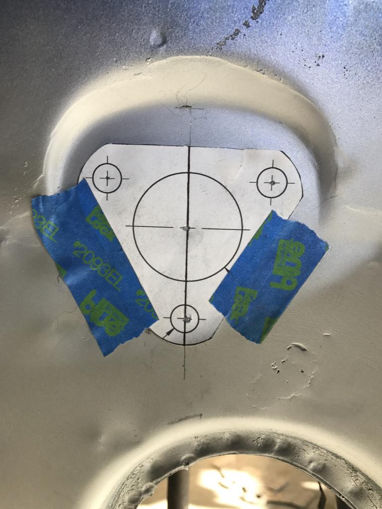
|
|
|
|
| tygaboy |
Oct 15 2017, 11:37 AM
Post
#672
|
|
914 Guru Group: Members Posts: 5,818 Joined: 6-October 15 From: Petaluma, CA Member No.: 19,241 Region Association: Northern California |
Artsy-fartsy shot through one hole looking to the one on the other side.
Attached thumbnail(s) 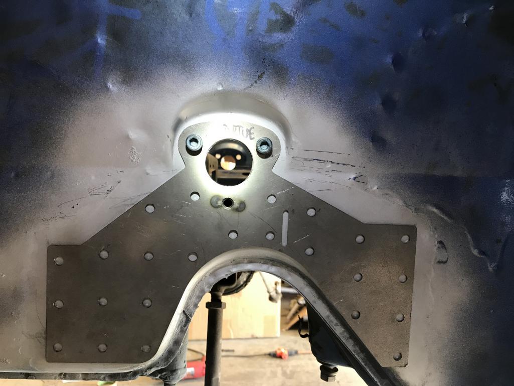
|
|
|
|
| tygaboy |
Oct 15 2017, 11:41 AM
Post
#673
|
|
914 Guru Group: Members Posts: 5,818 Joined: 6-October 15 From: Petaluma, CA Member No.: 19,241 Region Association: Northern California |
Here's the Elephant backer plate, trimmed to work with the welded on lower nut approach.
Rather than cut the backer plate so it sits just above that step in the sheet metal, I've started notching the back side. You can see I still have some tweaking to do to get it to lay down flat. I figured leaving this so it fully wraps around the bar will add just that much more strength to the area. Almost ready for final welding of all this! (IMG:style_emoticons/default/cheer.gif) Attached thumbnail(s) 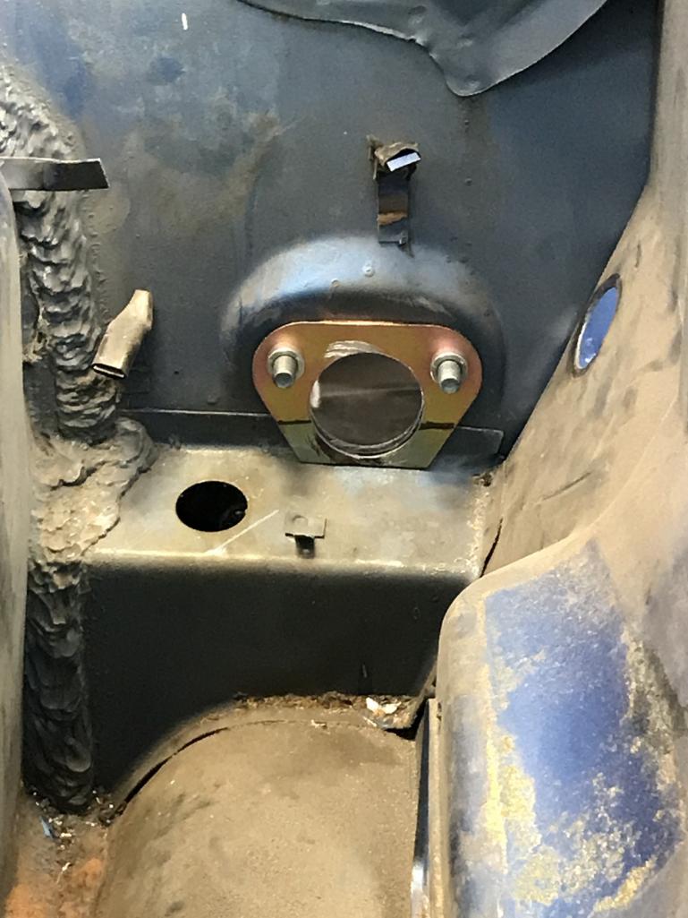
|
|
|
|
| tygaboy |
Oct 15 2017, 05:19 PM
Post
#674
|
|
914 Guru Group: Members Posts: 5,818 Joined: 6-October 15 From: Petaluma, CA Member No.: 19,241 Region Association: Northern California |
I have so many things to get to...
I had to move some parts around and ended up getting distracted by the front bumper. I need to ventilate it and have been thinking about various designs. This one has a couple significant dents in it so I figured I'd use it to practice. I don't know what size opening I need but I wanted something more aggressive looking than the traditional GT look. So I started with this: - wider, taller and with a bit of a taper I may go a bit wider but I'll wait til I get it back on the car to make that decision. Essentially, I'm headed toward the look in the 2nd pic. Pardon my usual MS Paint hack (especially if it's your car!) Attached thumbnail(s) 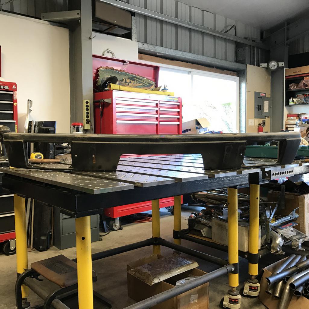 Attached image(s) 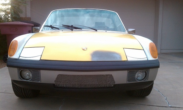
|
|
|
|
| Andyrew |
Oct 15 2017, 06:41 PM
Post
#675
|
|
Spooling.... Please wait Group: Members Posts: 13,380 Joined: 20-January 03 From: Riverbank, Ca Member No.: 172 Region Association: Northern California |
Bumper looks good. Should be enough flow, especially if you duct the exhaust.
|
|
|
|
| tygaboy |
Oct 16 2017, 07:48 AM
Post
#676
|
|
914 Guru Group: Members Posts: 5,818 Joined: 6-October 15 From: Petaluma, CA Member No.: 19,241 Region Association: Northern California |
QUOTE(Andyrew @ Oct 15 2017, 05:41 PM) Bumper looks good. Should be enough flow, especially if you duct the exhaust. Andrew - I'm planning the traditional "vent out the inner fender wells" approach - vs through the hood. Is there some equation for sq. inches of grill opening to sq. inches of the outlets that I should be leveraging? |
|
|
|
| Chris914n6 |
Oct 16 2017, 02:10 PM
Post
#677
|
|
Jackstands are my life. Group: Members Posts: 3,534 Joined: 14-March 03 From: Las Vegas, NV Member No.: 431 Region Association: Southwest Region |
QUOTE(tygaboy @ Oct 16 2017, 06:48 AM) QUOTE(Andyrew @ Oct 15 2017, 05:41 PM) Bumper looks good. Should be enough flow, especially if you duct the exhaust. Andrew - I'm planning the traditional "vent out the inner fender wells" approach - vs through the hood. Is there some equation for sq. inches of grill opening to sq. inches of the outlets that I should be leveraging? Outlets need to be at least 20% larger to accommodate heat expansion of the cooling air. You do some awesome work. |
|
|
|
| Andyrew |
Oct 17 2017, 08:31 AM
Post
#678
|
|
Spooling.... Please wait Group: Members Posts: 13,380 Joined: 20-January 03 From: Riverbank, Ca Member No.: 172 Region Association: Northern California |
I planned for 50% larger. Also when I mean duct I meant similar to what Kent just did, forcing the air to go where you want and separating it.
|
|
|
|
| andys |
Oct 17 2017, 10:42 AM
Post
#679
|
|
Advanced Member Group: Members Posts: 2,165 Joined: 21-May 03 From: Valencia, CA Member No.: 721 Region Association: None |
My former neighbor, vehicle designer and race car aero consultant, told me the general rule is 1.7x intake area. It does however, depend on the characteristics of the exhaust placement/configuration. The whole concept has to do with pressure differential, exhaust has to be in a lower pressure zone than the intake. Since the thru-wheel well exhaust has been done for a long time (mature technology), I'd go with what has worked in the past. BIGCAT has used a smaller than normal intake with great success; might give him a shout.
Andys |
|
|
|
| Rand |
Oct 17 2017, 11:24 AM
Post
#680
|
|
Cross Member Group: Members Posts: 7,415 Joined: 8-February 05 From: OR Member No.: 3,573 Region Association: None |
Your car is going to be crazy fast. Is the downforce difference between wheel well exit vs hood exit something to consider?
|
|
|
|
|
6 User(s) are reading this topic (6 Guests and 0 Anonymous Users)
0 Members:

|
Lo-Fi Version | Time is now: 28th April 2026 - 08:17 PM |
Invision Power Board
v9.1.4 © 2026 IPS, Inc.