|
|
|
Porsche, and the Porsche crest are registered trademarks of Dr. Ing. h.c. F. Porsche AG.
This site is not affiliated with Porsche in any way. Its only purpose is to provide an online forum for car enthusiasts. All other trademarks are property of their respective owners. |
|
|

  |

| pbanders |
 Oct 22 2016, 10:42 PM Oct 22 2016, 10:42 PM
Post
#1
|
|
Senior Member  Group: Members Posts: 990 Joined: 11-June 03 From: Scottsdale, AZ Member No.: 805 Region Association: Southwest Region |
These charts used to be available on my page but the javascript has been broken for years. Here are the individual charts, you start with the first one and branch to the other charts as needed. I'll come up with a new way to put them on my page so that they're accessible there.
Note that these charts were intended to help diagnose problems where the fuel pump isn't running at all. If your fuel pump runs for 1.5 sec after key on, but doesn't run after starting, you likely have a fault in your trigger contact (TC) points, the ECU, or the ECU wiring harness connections to the TC's. Note that the DMM should be set to DC voltage, and either in auto-range or on the manual 20V range. In the flow charts where it says "ground", that's the same as reading 0V on the DMM. I used "ground" and "0V" interchangeably, sorry for any confusion. Here's a diagram of the relay board so that you know what relays and connections are being referred to. This view is from the top side. 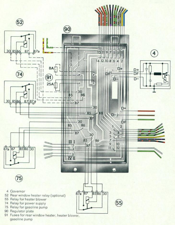 |
   |

 
|
| pbanders |
Oct 22 2016, 10:44 PM
Post
#2
|
|
Senior Member Group: Members Posts: 990 Joined: 11-June 03 From: Scottsdale, AZ Member No.: 805 Region Association: Southwest Region |
Start here, when you reach a red oval, go to the corresponding flow chart below:
 |
|
|
|
| pbanders |
Oct 22 2016, 10:45 PM
Post
#3
|
|
Senior Member Group: Members Posts: 990 Joined: 11-June 03 From: Scottsdale, AZ Member No.: 805 Region Association: Southwest Region |
Pwr to Relay Board:
 |
|
|
|
| pbanders |
Oct 22 2016, 10:47 PM
Post
#4
|
|
Senior Member Group: Members Posts: 990 Joined: 11-June 03 From: Scottsdale, AZ Member No.: 805 Region Association: Southwest Region |
ECU Pwr-Gnd Conn:
 |
|
|
|
| pbanders |
Oct 22 2016, 10:50 PM
Post
#5
|
|
Senior Member Group: Members Posts: 990 Joined: 11-June 03 From: Scottsdale, AZ Member No.: 805 Region Association: Southwest Region |
From previous flow chart, "Circuit is OK, leave DMM probe on pin III plug ECU back in and reinstall, reinstall air box assembly":
 |
|
|
|
| pbanders |
Oct 22 2016, 10:51 PM
Post
#6
|
|
Senior Member Group: Members Posts: 990 Joined: 11-June 03 From: Scottsdale, AZ Member No.: 805 Region Association: Southwest Region |
FP Pwr and ECU Control:
 |
|
|
|
| pbanders |
Oct 22 2016, 10:52 PM
Post
#7
|
|
Senior Member Group: Members Posts: 990 Joined: 11-June 03 From: Scottsdale, AZ Member No.: 805 Region Association: Southwest Region |
End Fault Area Diagnostics:
 |
|
|
|
| Spoke |
Oct 23 2016, 07:55 AM
Post
#8
|
|
Jerry Group: Members Posts: 7,370 Joined: 29-October 04 From: Allentown, PA Member No.: 3,031 Region Association: None |
QUOTE(pbanders @ Oct 23 2016, 12:44 AM)  Start here, when you reach a red oval, go to the corresponding flow chart below: Nice flowcharts. These should be very useful. On this chart, I was ok going down the chart but on the way back up at "Connect a DMM to pin III", I think an adjustment is needed in the flow. I believe the intent is to check the driving capability of the ECU to the FP on pin III. The ECU grounds pin III to turn on the FP. Here it should be mentioned to have the DMM set to Volts. On the next box, "Remove relay 74 turn key on" I am lost. Relay 74 is the power supply to the ECU. Removing relay 74 will disable the ECU permanently. Relay 74 should remain installed. The box should say "Turn key on". The next decision box "Ground for 1.5sec" should say "Measure 0V on DMM for 1.5sec after key on, then 12V. For the ending green box "FP System OK" only indicates the wiring to/from the FP including relay 75 and the ECU capability to drive relay 75 is ok. The FP system also includes the contacts on the distributor which tell the ECU the engine is turning and it should power the FP. If the contacts on the dizzy are not functional, the FP won't operate when starting the engine. Maybe this is a minor point in your flowchart and can be ignored. OT: BTW, I hate tracing the wiring on the relay board by seeing the routing of the relay board instead of having a real schematic of the board. It makes this job much harder. Anyone have a real schematic of the relay board? |
|
|
|
| pbanders |
Oct 23 2016, 08:43 AM
Post
#9
|
|
Senior Member Group: Members Posts: 990 Joined: 11-June 03 From: Scottsdale, AZ Member No.: 805 Region Association: Southwest Region |
Spoke, will check all of your comments, I haven't looked at these in about a decade and needed some eyes on them to check for errors, thanks.
|
|
|
|
| Tom_T |
Oct 23 2016, 12:10 PM
Post
#10
|
|
TMI.... Group: Members Posts: 8,321 Joined: 19-March 09 From: Orange, CA Member No.: 10,181 Region Association: Southern California |
|
|
|
|
| draganc |
Oct 23 2016, 12:12 PM
Post
#11
|
|
Senior Member Group: Members Posts: 725 Joined: 2-November 09 From: central new jersey Member No.: 11,000 Region Association: North East States |
Thanks for an excellent job done!
|
|
|
|
| pbanders |
Oct 23 2016, 12:50 PM
Post
#12
|
|
Senior Member Group: Members Posts: 990 Joined: 11-June 03 From: Scottsdale, AZ Member No.: 805 Region Association: Southwest Region |
QUOTE(Spoke @ Oct 23 2016, 06:55 AM) On the next box, "Remove relay 74 turn key on" I am lost. Relay 74 is the power supply to the ECU. Removing relay 74 will disable the ECU permanently. Relay 74 should remain installed. The box should say "Turn key on". Looks like I copied a version of the initial flow chart with an error on it, the version that's on my page references relay 75 instead, which is the fuel pump relay and not the power supply relay. I uploaded the correct flow chart. I added some text in the first posting about DMM settings and the interchangeable use of "ground" and "0V". I agree with your comment that "FP System OK" doesn't include verification that the fuel pump runs after starting, which is enabled by the ECU when it sees the TC's switching at above the cut-off level. I'll add a comment to the first posting to this effect, the charts were intended to address the "no fuel pump operation" problem. Thanks again for looking at these and please let me know if there are other issues that need fixing. |
|
|
|
| thomasotten |
Dec 1 2024, 03:37 PM
Post
#13
|
|
Senior Member Group: Members Posts: 1,572 Joined: 16-November 03 From: San Antonio, Texas Member No.: 1,349 |
Excellent flow charts. One thing to note, it appears that the relay board diagram is wrong. Specifically, Pins 85 and 86 are reversed. Here is a photo from my well worn Haynes manual which has it correct. I also verified with the actual relay Pins. I am not sure if your flow charts reference the actual Pins or if they also carry over the error.
Nevertheless, I appreciate the work. Thanks Attached image(s) 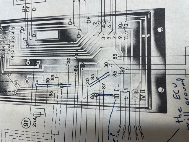
|
|
|
|
| ClayPerrine |
Dec 1 2024, 05:03 PM
Post
#14
|
|
Life's been good to me so far..... Group: Admin Posts: 16,542 Joined: 11-September 03 From: Hurst, TX. Member No.: 1,143 Region Association: NineFourteenerVille |
You can always use this relay board diagram.
(IMG:http://www.914world.com/bbs2/uploads/post-1143-1694107603.jpg) It didn't exist when this thread was started. It is much easier to read. |
|
|
|
|
1 User(s) are reading this topic (1 Guests and 0 Anonymous Users)
0 Members:

|
Lo-Fi Version | Time is now: 2nd April 2026 - 07:17 PM |
Invision Power Board
v9.1.4 © 2026 IPS, Inc.