|
|
|
Porsche, and the Porsche crest are registered trademarks of Dr. Ing. h.c. F. Porsche AG.
This site is not affiliated with Porsche in any way. Its only purpose is to provide an online forum for car enthusiasts. All other trademarks are property of their respective owners. |
|
|


| amfab |
 Jan 1 2017, 11:34 AM Jan 1 2017, 11:34 AM
Post
#1
|
|
Member  Group: Members Posts: 401 Joined: 17-May 16 From: Los Angeles Member No.: 20,004 Region Association: None |
OK, well I had to have a thread title. I am calling it that because it will restore structural integrity to the car and I want to be able to say that the rust has been correctly repaired if I eventually sell the car, unlike the lack of integrity of the person who hid the rust to sell it.
Pictures below The floor is a little shiny because there is still some mineral spirits on it from trying to get the tar off. The open areas that you are seeing are after I wire brushed with knotted wire wheels on a grinder, then a carbide burr on a die grinder. While I will take some more off, what you see is getting close to good weldable metal. First the longs: The driver’s side is the worst. The bottom edges inside and out were full of holes, or very thin, so I cut the outside of the driver’s all the way off—except I haven’t got to the front under the door pillar yet. I have cut out about 30 percent of the passenger’s side. The middle section is solid but I will replace it anyway. I started getting a little scared to take more out until I brace up the body. The floor pan: There are lots of sloppy welded patches and holes around the seams. The rear passenger’s and rear drivers quarters of the floor pan have been replaced with some plain steel—blue for some reason. The PO welded a solid bar on each side to mount the seat hinges. Sloppy, unground welds abound. There are some rust-through spots at the front of the pan that will need patching, but overall the pan in front of the cross member is solid. Some patches in the lower firewall are solid. Measuring diagonally, window frame to targa bar and straight back window frame to targa bar it is off no more than 1/8 inch. This changes depending upon doors open or closed or movement of the jack stands. The door gaps were never problems—maybe the driver’s side was a little wide. So it seems the car is pretty within spec and adjustable doorframe bars should be able to pull—or push—things to be good Here is where I need advice. This is my plan, please give feedback: 1) Pull Wiring harness, speedometer cable and gas lines out of the center tunnel (What else is in there?) pull gas tank. 2) Pull doors and build adjustable bars to align doorframes 3) Continue to grind back to clean metal in the inside of the longs. Sandblast, then create internal angled patch pieces to repair the inner longitudinals from 18ga cold rolled. I am using michelko’s example see: http://www.914world.com/bbs2/index.php?s=&...st&p=219748 4) Cut off the majority of the inner rockers (The upper half or three quarters of the longs are very solid) and replace with inner rockers from Restoration Design. 5) Coat interiors of longs with Ospho then Eastwood frame coating 6) Patch any inner long parts to the area aft of the Restoration Design patch with 18ga cold rolled steel. 7) Install Brad Mayuer reinforcement kit over the longs 8) Cut rear floor quarters and cross member out 9) Weld in new rear floor panel and cross member, grinding out old welds and creating flanges from18ga where necessary—in the spots where there is no flange left in spots along the firewall and inner long 10) Remove and rebuild pedal cluster and create patches for small rust spots in the front of the footwells. 11) Sandblast interior and prime and paint. 12) Cut holes for front sway bar, sand blast and prime and paint bottom of gas tank area. 13) Install gas tank, new stainless gas lines and reinstall wiring harness. Please give any feedback regarding my plan 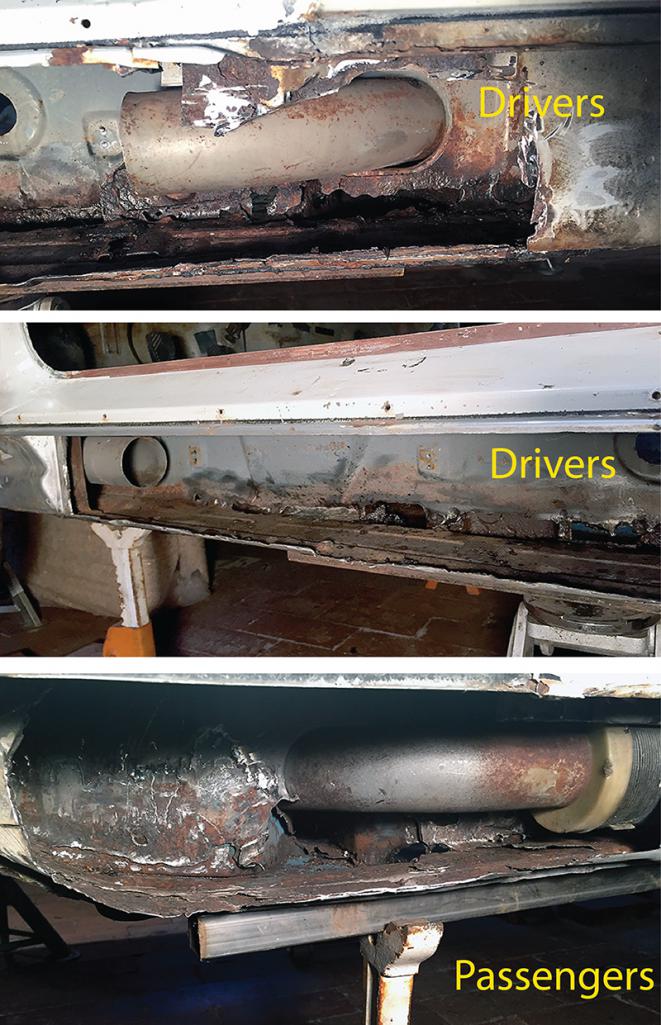 Attached thumbnail(s) 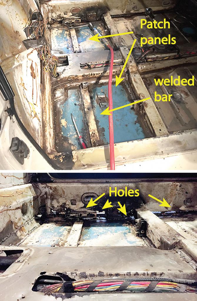
|
   |

 
|
Posts in this topic
 amfab Operation Integrity Jan 1 2017, 11:34 AM
 amfab More Picts Jan 1 2017, 11:36 AM GeorgeRud You'll have some welding to do, but Restoratio... Jan 1 2017, 02:19 PM cary Adding to George's suggestion.
Do you have do... Jan 1 2017, 10:04 PM
amfab More Picts Jan 1 2017, 11:36 AM GeorgeRud You'll have some welding to do, but Restoratio... Jan 1 2017, 02:19 PM cary Adding to George's suggestion.
Do you have do... Jan 1 2017, 10:04 PM
 amfab
Adding to George's suggestion.
Do you have d... Jan 2 2017, 12:03 PM amfab What do you guys think about welding a place under... Jan 2 2017, 08:56 PM Andyrew At this point you have so little structural integr... Jan 2 2017, 09:03 PM amfab Thanks for the link Andrew there is some very rele... Jan 4 2017, 10:48 PM mbseto I wanted to do braces that would allow putting the... Jan 5 2017, 05:02 PM tygaboy
I wanted to do braces that would allow putting th... Jan 6 2017, 09:20 PM trojanhorsepower If you are interested in the opinion of someone th... Jan 7 2017, 09:08 AM amfab I agree it is better to build a jig and do a full ... Jan 9 2017, 07:41 PM mbseto Is that hydraulic bearing weight? I've found ... Jan 10 2017, 10:00 AM amfab
Is that hydraulic bearing weight? I've found... Jan 10 2017, 10:15 AM amfab OK making patches. Can you guys le me know if this... Jan 15 2017, 07:13 PM mbseto You're planning a reinforcement kit on the out... Jan 16 2017, 09:08 AM amfab
You're planning a reinforcement kit on the ou... Jan 16 2017, 10:05 AM Andyrew Looks good. If your doing it on the inside then ma... Jan 16 2017, 12:31 PM amfab OK, so based on Andyrew's comments I went out ... Jan 21 2017, 08:15 PM Montreal914 To give you an idea, the holes for the plug welds ... Jan 21 2017, 10:27 PM amfab
To give you an idea, the holes for the plug welds... Jan 22 2017, 10:03 PM BeatNavy
I just said "screw it" and ordered a re... Jan 23 2017, 04:35 AM amfab
I can't tell by your description - are you d... Jan 23 2017, 11:48 PM amfab You guys intimidate me. I am ok with a TIG, but I ... Jan 30 2017, 10:39 PM BeatNavy
Do you guys run .030 or .025?
Im using .030 with ... Jan 31 2017, 04:50 AM BillC
You guys intimidate me. I am ok with a TIG, but I... Jan 31 2017, 08:15 AM bretth One issue I have encountered while welding with th... Jan 31 2017, 08:31 AM amfab You guys have me thinking about a few things.
I h... Jan 31 2017, 01:26 PM bdstone914 Larger hole make the welds easier. 3/8 minimum. Feb 5 2017, 11:18 AM amfab OK, here I am about a year later, the project bein... Dec 5 2018, 06:58 PM amfab The floor pans and outer longs will be replaced by... Dec 5 2018, 07:01 PM amfab The upper firewall had some sloppy patches, so I g... Dec 5 2018, 07:13 PM amfab As you can see from the above patch photos the low... Dec 5 2018, 07:25 PM amfab I was delayed for a few months because of work and... Dec 5 2018, 07:30 PM Dion Sorry about the other cars getting nailed, that su... Dec 5 2018, 07:38 PM amfab Thanks Dion,
I ended up having the 993 repainted.... Dec 5 2018, 09:04 PM amfab I bought some Used Interlake pallet rack shelf sup... Dec 6 2018, 01:29 PM amfab Once on the rotisserie the dolly frame really keep... Dec 6 2018, 01:35 PM 76-914
Once on the rotisserie the dolly frame really kee... Dec 6 2018, 01:52 PM amfab
I was going about 15 mph and and a brand new—n... Dec 6 2018, 02:00 PM amfab I don't know why the P.O. did this. He probabl... Dec 6 2018, 01:42 PM bbrock Fantastic work. I absolutely LOVE that dolly-roti... Dec 6 2018, 01:52 PM amfab
Fantastic work. I absolutely LOVE that dolly-rot... Dec 8 2018, 09:52 PM amfab This one comes not from the P.O.—just from rust.... Dec 6 2018, 01:53 PM amfab Unfortunately, the Restoration design floor pan en... Dec 6 2018, 04:24 PM dr914@autoatlanta.com congrats on saving the car, we just did one that w... Dec 6 2018, 04:32 PM amfab wow, when you repost the first page and I look at ... Dec 6 2018, 04:47 PM Tdskip Great thread-I’m late to the party but thank you... Dec 9 2018, 10:15 AM amfab
Great thread-I’m late to the party but thank yo... Dec 9 2018, 11:28 AM Tdskip
[quote name='Tdskip' post='2672376' date='Dec 9 2... Dec 9 2018, 12:40 PM amfab Well I am swearing at it today, I have some thin s... Dec 9 2018, 02:15 PM bbrock
Well I am swearing at it today, I have some thin ... Dec 9 2018, 02:54 PM Tdskip
Well I am swearing at it today, I have some thin... Dec 9 2018, 04:46 PM amfab yeah, I have a couple copper backing things. Still... Dec 9 2018, 04:51 PM bbrock I feel your pain. Especially hard when you spent ... Dec 9 2018, 06:25 PM Tdskip What do you use to grind? Flap wheel? Dec 9 2018, 07:56 PM bbrock Flap wheel generates too much heat. Too easy to w... Dec 9 2018, 08:10 PM amfab Dollisserie I like that.
Maybe its my fondness fo... Dec 9 2018, 08:18 PM bbrock Yeah, in addition to heat, they eat a lot of metal... Dec 9 2018, 08:55 PM amfab
Yeah, in addition to heat, they eat a lot of meta... Dec 9 2018, 09:05 PM
amfab
Adding to George's suggestion.
Do you have d... Jan 2 2017, 12:03 PM amfab What do you guys think about welding a place under... Jan 2 2017, 08:56 PM Andyrew At this point you have so little structural integr... Jan 2 2017, 09:03 PM amfab Thanks for the link Andrew there is some very rele... Jan 4 2017, 10:48 PM mbseto I wanted to do braces that would allow putting the... Jan 5 2017, 05:02 PM tygaboy
I wanted to do braces that would allow putting th... Jan 6 2017, 09:20 PM trojanhorsepower If you are interested in the opinion of someone th... Jan 7 2017, 09:08 AM amfab I agree it is better to build a jig and do a full ... Jan 9 2017, 07:41 PM mbseto Is that hydraulic bearing weight? I've found ... Jan 10 2017, 10:00 AM amfab
Is that hydraulic bearing weight? I've found... Jan 10 2017, 10:15 AM amfab OK making patches. Can you guys le me know if this... Jan 15 2017, 07:13 PM mbseto You're planning a reinforcement kit on the out... Jan 16 2017, 09:08 AM amfab
You're planning a reinforcement kit on the ou... Jan 16 2017, 10:05 AM Andyrew Looks good. If your doing it on the inside then ma... Jan 16 2017, 12:31 PM amfab OK, so based on Andyrew's comments I went out ... Jan 21 2017, 08:15 PM Montreal914 To give you an idea, the holes for the plug welds ... Jan 21 2017, 10:27 PM amfab
To give you an idea, the holes for the plug welds... Jan 22 2017, 10:03 PM BeatNavy
I just said "screw it" and ordered a re... Jan 23 2017, 04:35 AM amfab
I can't tell by your description - are you d... Jan 23 2017, 11:48 PM amfab You guys intimidate me. I am ok with a TIG, but I ... Jan 30 2017, 10:39 PM BeatNavy
Do you guys run .030 or .025?
Im using .030 with ... Jan 31 2017, 04:50 AM BillC
You guys intimidate me. I am ok with a TIG, but I... Jan 31 2017, 08:15 AM bretth One issue I have encountered while welding with th... Jan 31 2017, 08:31 AM amfab You guys have me thinking about a few things.
I h... Jan 31 2017, 01:26 PM bdstone914 Larger hole make the welds easier. 3/8 minimum. Feb 5 2017, 11:18 AM amfab OK, here I am about a year later, the project bein... Dec 5 2018, 06:58 PM amfab The floor pans and outer longs will be replaced by... Dec 5 2018, 07:01 PM amfab The upper firewall had some sloppy patches, so I g... Dec 5 2018, 07:13 PM amfab As you can see from the above patch photos the low... Dec 5 2018, 07:25 PM amfab I was delayed for a few months because of work and... Dec 5 2018, 07:30 PM Dion Sorry about the other cars getting nailed, that su... Dec 5 2018, 07:38 PM amfab Thanks Dion,
I ended up having the 993 repainted.... Dec 5 2018, 09:04 PM amfab I bought some Used Interlake pallet rack shelf sup... Dec 6 2018, 01:29 PM amfab Once on the rotisserie the dolly frame really keep... Dec 6 2018, 01:35 PM 76-914
Once on the rotisserie the dolly frame really kee... Dec 6 2018, 01:52 PM amfab
I was going about 15 mph and and a brand new—n... Dec 6 2018, 02:00 PM amfab I don't know why the P.O. did this. He probabl... Dec 6 2018, 01:42 PM bbrock Fantastic work. I absolutely LOVE that dolly-roti... Dec 6 2018, 01:52 PM amfab
Fantastic work. I absolutely LOVE that dolly-rot... Dec 8 2018, 09:52 PM amfab This one comes not from the P.O.—just from rust.... Dec 6 2018, 01:53 PM amfab Unfortunately, the Restoration design floor pan en... Dec 6 2018, 04:24 PM dr914@autoatlanta.com congrats on saving the car, we just did one that w... Dec 6 2018, 04:32 PM amfab wow, when you repost the first page and I look at ... Dec 6 2018, 04:47 PM Tdskip Great thread-I’m late to the party but thank you... Dec 9 2018, 10:15 AM amfab
Great thread-I’m late to the party but thank yo... Dec 9 2018, 11:28 AM Tdskip
[quote name='Tdskip' post='2672376' date='Dec 9 2... Dec 9 2018, 12:40 PM amfab Well I am swearing at it today, I have some thin s... Dec 9 2018, 02:15 PM bbrock
Well I am swearing at it today, I have some thin ... Dec 9 2018, 02:54 PM Tdskip
Well I am swearing at it today, I have some thin... Dec 9 2018, 04:46 PM amfab yeah, I have a couple copper backing things. Still... Dec 9 2018, 04:51 PM bbrock I feel your pain. Especially hard when you spent ... Dec 9 2018, 06:25 PM Tdskip What do you use to grind? Flap wheel? Dec 9 2018, 07:56 PM bbrock Flap wheel generates too much heat. Too easy to w... Dec 9 2018, 08:10 PM amfab Dollisserie I like that.
Maybe its my fondness fo... Dec 9 2018, 08:18 PM bbrock Yeah, in addition to heat, they eat a lot of metal... Dec 9 2018, 08:55 PM amfab
Yeah, in addition to heat, they eat a lot of meta... Dec 9 2018, 09:05 PM  |
1 User(s) are reading this topic (1 Guests and 0 Anonymous Users)
0 Members:

|
Lo-Fi Version | Time is now: 23rd June 2026 - 02:23 PM |
Invision Power Board
v9.1.4 © 2026 IPS, Inc.