|
|
|
Porsche, and the Porsche crest are registered trademarks of Dr. Ing. h.c. F. Porsche AG.
This site is not affiliated with Porsche in any way. Its only purpose is to provide an online forum for car enthusiasts. All other trademarks are property of their respective owners. |
|
|

  |

| gfg3 |
 Jan 30 2017, 10:43 AM Jan 30 2017, 10:43 AM
Post
#1
|
|
Never Too Old  Group: Members Posts: 121 Joined: 5-January 15 From: Southern Virginia Member No.: 18,295 Region Association: None |
I've spent the past several days trying to find a picture of the back of my combo gauge showing the wiring (or a wiring diagram). I have various current flow diagrams and I've found the info for lots of other 914 combo gauges but not for this one (part # 914-641-101-50).
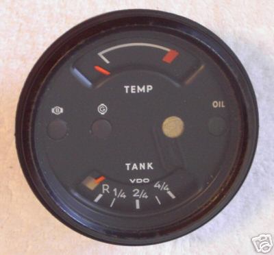 According to the Parts Vault (thanks for the picture - better than I could have done) this gauge was for 74, 75, 76 914/4 2.0 cars which came without a center console. It's mounted on the left side of my dash. Not working properly, but just in case the PO fiddled with it, I'd like to see how it's supposed to be wired before I dive into it. I'm not an electrical expert, so simpler is better. Can anyone help? Thanks. George |
   |

 
|
| JFG |
Jan 30 2017, 12:10 PM
Post
#2
|
|
Senior Member Group: Members Posts: 686 Joined: 7-April 16 From: Wales Member No.: 19,869 Region Association: None |
http://forums.pelicanparts.com/porsche-914...where-goes.html
is this any good? i'm not good at electricals either so hope it helps |
|
|
|
| JFG |
Jan 30 2017, 12:15 PM
Post
#3
|
|
Senior Member Group: Members Posts: 686 Joined: 7-April 16 From: Wales Member No.: 19,869 Region Association: None |
or this? |
|
|
|
| gfg3 |
Jan 30 2017, 12:54 PM
Post
#4
|
|
Never Too Old Group: Members Posts: 121 Joined: 5-January 15 From: Southern Virginia Member No.: 18,295 Region Association: None |
QUOTE(JFG @ Jan 30 2017, 01:10 PM)  is this any good? i'm not good at electricals either so hope it helps Saw this post, but this is different combo gauge. Good info in the posts about wire colors, but I'd sure like to see how it all hooks up to my gauge. Thanks anyway. George |
|
|
|
| StratPlayer |
Jan 30 2017, 01:02 PM
Post
#5
|
|
StratPlayer Group: Members Posts: 3,338 Joined: 27-December 02 From: SLC, Utah Member No.: 27 Region Association: Rocky Mountains |
Hope this helps
Attached image(s) 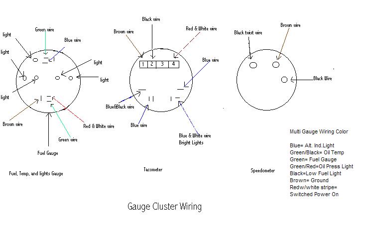
|
|
|
|
| gfg3 |
Jan 30 2017, 01:09 PM
Post
#6
|
|
Never Too Old Group: Members Posts: 121 Joined: 5-January 15 From: Southern Virginia Member No.: 18,295 Region Association: None |
QUOTE(StratPlayer @ Jan 30 2017, 02:02 PM) Hope this helps This looks like it. Thanks much! If I run into more difficulties once I pull the gauge I'll be sure to ask again. Love this site! George |
|
|
|
| bandjoey |
Jan 30 2017, 01:18 PM
Post
#7
|
|
bandjoey Group: Members Posts: 4,934 Joined: 26-September 07 From: Bedford Tx Member No.: 8,156 Region Association: Southwest Region |
Or this too
As I was told the temp part requires power, ground, and the wire from the taco plate. http://www.p914.com/p914_gauges_fuel.htm |
|
|
|
| gfg3 |
Jan 30 2017, 01:48 PM
Post
#8
|
|
Never Too Old Group: Members Posts: 121 Joined: 5-January 15 From: Southern Virginia Member No.: 18,295 Region Association: None |
QUOTE(bandjoey @ Jan 30 2017, 02:18 PM) Or this too As I was told the temp part requires power, ground, and the wire from the taco plate. Thanks! I think that between your info here, the drawing that StratPlayer posted and the info in some of the earlier posts, I should be able to reconstruct "truth". If I come up with a workable drawing I'll post it to get comments. George |
|
|
|
| JFG |
Jan 30 2017, 02:40 PM
Post
#9
|
|
Senior Member Group: Members Posts: 686 Joined: 7-April 16 From: Wales Member No.: 19,869 Region Association: None |
I'm going to need that drawing for deconstructing the birds nest that is my cabin wiring loom. Thanks
|
|
|
|
| gfg3 |
Jan 31 2017, 03:39 PM
Post
#10
|
|
Never Too Old Group: Members Posts: 121 Joined: 5-January 15 From: Southern Virginia Member No.: 18,295 Region Association: None |
QUOTE(JFG @ Jan 30 2017, 03:40 PM) I'm going to need that drawing for deconstructing the birds nest that is my cabin wiring loom. Thanks OK. Here's what I came up with for the alternative combo gauge for '74 and newer 2.0 cars without the center console. I used several current flow diagrams and photos of the back of an unwired gauge. No warranties expressed or implied. In fact, since I am not an electrical guru, I would welcome anyone who actually can read wiring diagrams to critique this. I think I got the wire colors and connections close to being right, but who knows? Also, all the red/white wires are the various switched power connections. I assume they come together somewhere. Oh, and I know that ground has its own special symbol, but I was too lazy to build it in Powerpoint. Anyway, please....critique away. George 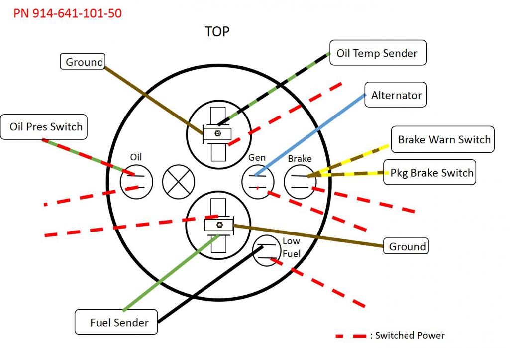 |
|
|
|
| EdwardBlume |
Oct 11 2017, 07:37 PM
Post
#11
|
|
914 Wizard Group: Members Posts: 12,338 Joined: 2-January 03 From: SLO Member No.: 81 Region Association: Central California |
QUOTE(StratPlayer @ Jan 30 2017, 12:02 PM) Hope this helps Sorry for the hijack, but is there no black / blue wire necessary for this combo gauge? Its supposed to be the original background lamp, but the combo gauge doesn't seem to have it. |
|
|
|
| Larmo63 |
Oct 11 2017, 07:47 PM
Post
#12
|
|
Advanced Member Group: Members Posts: 4,267 Joined: 3-March 14 From: San Clemente, Ca Member No.: 17,068 Region Association: Southern California |
All gauge lights are black w/blue tracer....
Right? Btw, where does one source the teeny bulbs for the center heater control sliders? |
|
|
|
| EdwardBlume |
Oct 12 2017, 05:43 AM
Post
#13
|
|
914 Wizard Group: Members Posts: 12,338 Joined: 2-January 03 From: SLO Member No.: 81 Region Association: Central California |
QUOTE(Larmo63 @ Oct 11 2017, 06:47 PM) All gauge lights are black w/blue tracer.... Right? Btw, where does one source the teeny bulbs for the center heater control sliders? Yes, the black with blue tracer is in the Bowlsby original diagram, but the combo gauge above doesn't have it. is this correct? |
|
|
|
| worn |
Oct 12 2017, 09:25 AM
Post
#14
|
|
Winner of the Utah Twisted Joint Award Group: Members Posts: 3,492 Joined: 3-June 11 From: Madison, WI Member No.: 13,152 Region Association: Upper MidWest |
Sort of on topic - the alternator needs the correct GEN warning light bulb to function. If you are tempted to go all LED while you are there, don't use one for that warning light.
|
|
|
|
| EdwardBlume |
Oct 12 2017, 10:28 AM
Post
#15
|
|
914 Wizard Group: Members Posts: 12,338 Joined: 2-January 03 From: SLO Member No.: 81 Region Association: Central California |
Here's the Bowlsby diagram. The black with blue wire is present on stock, but not on the combo gauge. Correct? Do I just tape it off?
Attached image(s) 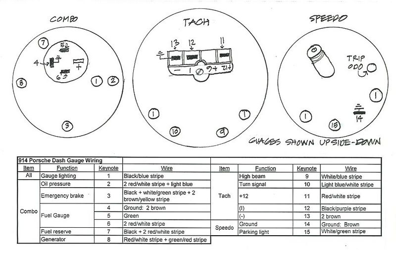
|
|
|
|
| Jonathan Livesay |
Oct 12 2017, 11:05 AM
Post
#16
|
|
Senior Member Group: Members Posts: 745 Joined: 13-March 10 From: La Canada CA Member No.: 11,461 Region Association: None |
QUOTE(gfg3 @ Jan 31 2017, 02:39 PM) QUOTE(JFG @ Jan 30 2017, 03:40 PM) I'm going to need that drawing for deconstructing the birds nest that is my cabin wiring loom. Thanks OK. Here's what I came up with for the alternative combo gauge for '74 and newer 2.0 cars without the center console. I used several current flow diagrams and photos of the back of an unwired gauge. No warranties expressed or implied. In fact, since I am not an electrical guru, I would welcome anyone who actually can read wiring diagrams to critique this. I think I got the wire colors and connections close to being right, but who knows? Also, all the red/white wires are the various switched power connections. I assume they come together somewhere. Oh, and I know that ground has its own special symbol, but I was too lazy to build it in Powerpoint. Anyway, please....critique away. George The black/purple wire goes to the bulb next to the oil pressure light and lights the gauge. Where the circle with the X in it is in the diagram. |
|
|
|
| timothy_nd28 |
Oct 12 2017, 11:13 AM
Post
#17
|
|
Advanced Member Group: Members Posts: 2,299 Joined: 25-September 07 From: IN Member No.: 8,154 Region Association: Upper MidWest |
If you put the black/purple wire on a lamp, the engine will cease to run
|
|
|
|
| EdwardBlume |
Oct 12 2017, 11:35 AM
Post
#18
|
|
914 Wizard Group: Members Posts: 12,338 Joined: 2-January 03 From: SLO Member No.: 81 Region Association: Central California |
QUOTE(timothy_nd28 @ Oct 12 2017, 10:13 AM) If you put the black/purple wire on a lamp, the engine will cease to run Are you answering the prior post? Where the X goes? I agree that the X misses the mark. If you look in post 1 here, its an amber warning light. Bowlsby's diagram lists it as gauge lighting. #1 |
|
|
|
| Jonathan Livesay |
Oct 12 2017, 12:05 PM
Post
#19
|
|
Senior Member Group: Members Posts: 745 Joined: 13-March 10 From: La Canada CA Member No.: 11,461 Region Association: None |
QUOTE(Edward Blume @ Oct 12 2017, 10:35 AM) QUOTE(timothy_nd28 @ Oct 12 2017, 10:13 AM) If you put the black/purple wire on a lamp, the engine will cease to run Are you answering the prior post? Where the X goes? I agree that the X misses the mark. If you look in post 1 here, its an amber warning light. Bowlsby's diagram lists it as gauge lighting. #1 The off white dot is just for looks, no light goes through it, the bulb in that space lights both the gas and temp. gauges. |
|
|
|
| Jonathan Livesay |
Oct 12 2017, 12:17 PM
Post
#20
|
|
Senior Member Group: Members Posts: 745 Joined: 13-March 10 From: La Canada CA Member No.: 11,461 Region Association: None |
QUOTE(timothy_nd28 @ Oct 12 2017, 10:13 AM) If you put the black/purple wire on a lamp, the engine will cease to run Yeah, oops I meant to say black and blue wire, does that make more sense? (IMG:style_emoticons/default/dry.gif) |
|
|
|
|
1 User(s) are reading this topic (1 Guests and 0 Anonymous Users)
0 Members:

|
Lo-Fi Version | Time is now: 19th July 2025 - 12:00 AM |
Invision Power Board
v9.1.4 © 2025 IPS, Inc.