|
|
|
Porsche, and the Porsche crest are registered trademarks of Dr. Ing. h.c. F. Porsche AG.
This site is not affiliated with Porsche in any way. Its only purpose is to provide an online forum for car enthusiasts. All other trademarks are property of their respective owners. |
|
|

  |

| vin man |
 Feb 7 2017, 03:20 PM Feb 7 2017, 03:20 PM
Post
#1
|
|
Member  Group: Members Posts: 178 Joined: 19-February 10 From: Gilbert, Arizona USA Member No.: 11,380 Region Association: Southwest Region |
I've done some searching and have not yet found a thread that I'm sure has been covered at some point.
The tach in my 72 does not work. The car was converted from fuel injection to carbs long ago. I believe the reason the tach does not work is because it is no longer getting a signal from the computer (no longer have an ECU in the car). How does one use the factory tach when I no longer have FI? In other car projects, I just ran a line from negative side of the coil to the back of the tach. But I don't think that will work here, will it? |
   |

 
|
| timothy_nd28 |
Feb 7 2017, 04:19 PM
Post
#2
|
|
Advanced Member Group: Members Posts: 2,299 Joined: 25-September 07 From: IN Member No.: 8,154 Region Association: Upper MidWest |
There is already a black with purple stripe wire that runs from the tach to the negative terminal of the ignition coil. All 914 tachometers read the tach signal from the ignition coil, not the computer.
So back to your troubleshooting, there is only 3 wires needed to make this tachometer work. The two outside terminals on the tach should have a brown wire while the other wire should be red with white stripe. These are the power wires. You should measure 12vdc between these two wires with the ignition switch is set to on. The middle wire (black with purple stripe) is the signal wire. You will want to ohm this wire from the negative terminal of the ignition coil to the middle terminal of your tachometer. You should get 0 ohms. If all that fails, you may have a bad tachometer. |
|
|
|
| TheCabinetmaker |
Feb 7 2017, 04:28 PM
Post
#3
|
|
I drive my car everyday Group: Members Posts: 8,378 Joined: 8-May 03 From: Tulsa, Ok. Member No.: 666 |
The djet cars have a large black power wire, a small black with purple stripe (tach), and a green wire from the condenser. Condenser and tach go on the same side.
|
|
|
|
| vin man |
Feb 7 2017, 04:28 PM
Post
#4
|
|
Member Group: Members Posts: 178 Joined: 19-February 10 From: Gilbert, Arizona USA Member No.: 11,380 Region Association: Southwest Region |
Thanks. On my way over to test as you suggest.
|
|
|
|
| vin man |
Feb 7 2017, 07:06 PM
Post
#5
|
|
Member Group: Members Posts: 178 Joined: 19-February 10 From: Gilbert, Arizona USA Member No.: 11,380 Region Association: Southwest Region |
According the repair manual I have, the wire from the back of the tach (black with purple) goes to a "ballast resistor". I've read in other threads that in later models, the resistor is internal to the tach. Or maybe the ballast resistor only used on the 914 /6.
Anyways, when I tracked the black/purple wire back, it went to the relay board in the engine compartment. There was not a black with purple wire coming off the negative side of the coil, but instead a green with red. I disconnected the green with red and spliced a wire right into the black with purple wire. Tach is now working! Thanks everyone. |
|
|
|
| TheCabinetmaker |
Feb 7 2017, 07:52 PM
Post
#6
|
|
I drive my car everyday Group: Members Posts: 8,378 Joined: 8-May 03 From: Tulsa, Ok. Member No.: 666 |
Green with red is the oil pressure sender.
|
|
|
|
| vin man |
Feb 7 2017, 08:02 PM
Post
#7
|
|
Member Group: Members Posts: 178 Joined: 19-February 10 From: Gilbert, Arizona USA Member No.: 11,380 Region Association: Southwest Region |
That's right. Maybe the wire for the tech was green and black. I don't remember for sure. But nonetheless it works now
|
|
|
|
| timothy_nd28 |
Feb 7 2017, 08:39 PM
Post
#8
|
|
Advanced Member Group: Members Posts: 2,299 Joined: 25-September 07 From: IN Member No.: 8,154 Region Association: Upper MidWest |
I'm just curious, where was the black and purple wire plugged into?
|
|
|
|
| 914werke |
Feb 7 2017, 10:02 PM
Post
#9
|
|
"I got blisters on me fingers" Group: Members Posts: 11,692 Joined: 22-March 03 From: USofA Member No.: 453 Region Association: Pacific Northwest |
Tim is there a way to simulate the signals to "bench" test the tach?
|
|
|
|
| vin man |
Feb 7 2017, 10:09 PM
Post
#10
|
|
Member Group: Members Posts: 178 Joined: 19-February 10 From: Gilbert, Arizona USA Member No.: 11,380 Region Association: Southwest Region |
The black with purple stripe wire came to this plug on the relay board. You can also see the gray wire I spliced into it and ran over to the coil.
(IMG:http://www.914world.com/bbs2/uploads_offsite/i304.photobucket.com-11380-1486526983.1.jpg) (IMG:http://www.914world.com/bbs2/uploads_offsite/i304.photobucket.com-11380-1486526984.2.jpg) |
|
|
|
| timothy_nd28 |
Feb 7 2017, 10:18 PM
Post
#11
|
|
Advanced Member Group: Members Posts: 2,299 Joined: 25-September 07 From: IN Member No.: 8,154 Region Association: Upper MidWest |
20 bucks in Radio Shack parts and a Iphone (or similar), yes you can. I built my own signal amplifier a few years back, and it still works great.
You need to amplify these following frequencies: 33.3, 66.6, 100, 133, 166, 200hz Each frequency correlates to engine rpm. 33.3 hz is 1000 rpm, 66.6hz is 2000 rpm, 100hz is 3000 rpm and so on. The iphone has many good apps that you can download which will simulate these frequencies, but the amplitude of these frequencies is the problem as you will only get 1.4 volts from your phone's headphone jack. The tachometer needs to see atleast 30 volts before it will start moving. Buying a few transformers and a very standard JAN2222a transistor, you can build a circuit that will amplify the 1.4 volts to around 60 volts, enough to drive the tachometer. If you are interested, I can get you a schematic. |
|
|
|
| timothy_nd28 |
Feb 7 2017, 10:24 PM
Post
#12
|
|
Advanced Member Group: Members Posts: 2,299 Joined: 25-September 07 From: IN Member No.: 8,154 Region Association: Upper MidWest |
The black/purple stripe wire should enter on the 14 pin connector at pin 7. It continues thru the relay board and exits pin 5 of the 12 pin connector.
You should check the 12 pin connector on the relay board, if you take a peek you will see a black/purple stripe wire. Follow it, see where it goes. 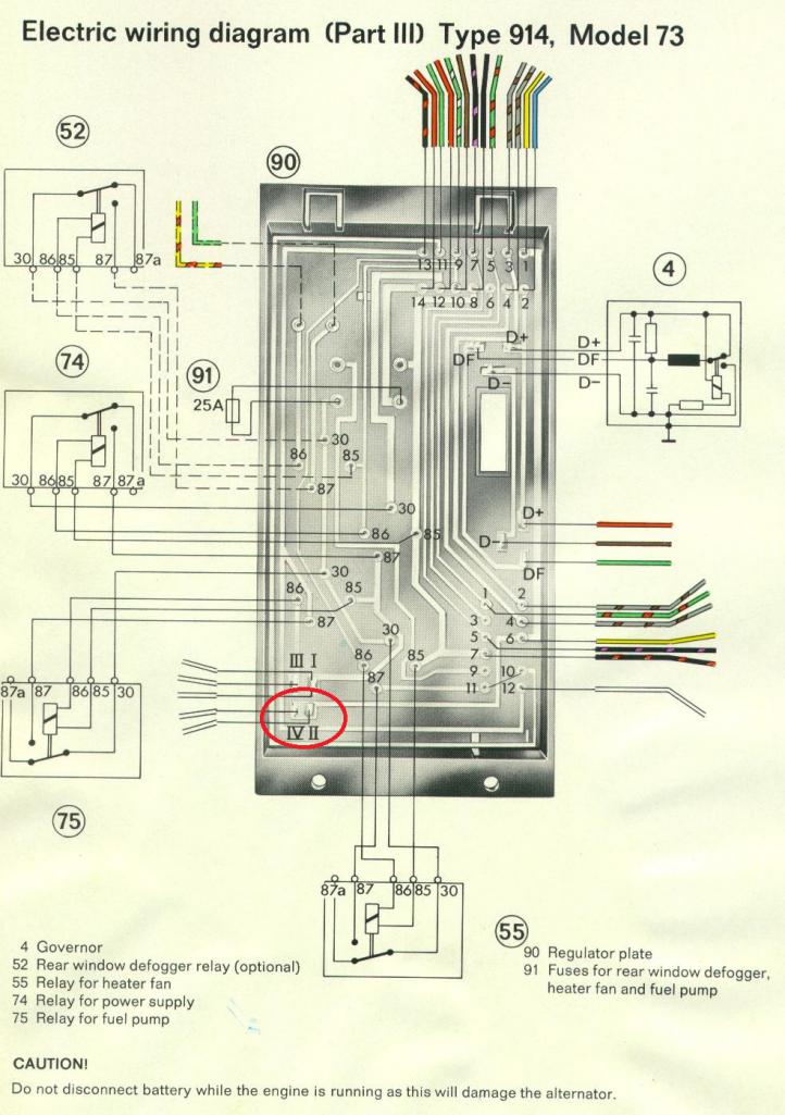 |
|
|
|
| vin man |
Feb 8 2017, 09:32 AM
Post
#13
|
|
Member Group: Members Posts: 178 Joined: 19-February 10 From: Gilbert, Arizona USA Member No.: 11,380 Region Association: Southwest Region |
QUOTE(timothy_nd28 @ Feb 7 2017, 09:24 PM)  The black/purple stripe wire should enter on the 14 pin connector at pin 7. It continues thru the relay board and exits pin 5 of the 12 pin connector. You should check the 12 pin connector on the relay board, if you take a peek you will see a black/purple stripe wire. Follow it, see where it goes. Is the 12 pin the one closer to the firewall? That is the one that I spliced on to and ran to the coil. If not, I will look to see if I find a black/purple wire on the other connector and see where it goes. It definitely wasn't on the coil. |
|
|
|
| timothy_nd28 |
Feb 8 2017, 10:01 AM
Post
#14
|
|
Advanced Member Group: Members Posts: 2,299 Joined: 25-September 07 From: IN Member No.: 8,154 Region Association: Upper MidWest |
12 pin connector is not the one by the firewall
|
|
|
|
| vin man |
Feb 8 2017, 10:15 AM
Post
#15
|
|
Member Group: Members Posts: 178 Joined: 19-February 10 From: Gilbert, Arizona USA Member No.: 11,380 Region Association: Southwest Region |
QUOTE(timothy_nd28 @ Feb 8 2017, 09:01 AM) 12 pin connector is not the one by the firewall Ok, thanks. When I go over to my workshop tonight after work, I will trace the black/purple wire out of the 12 pin connector and see where it goes. |
|
|
|
| vin man |
Feb 8 2017, 10:18 AM
Post
#16
|
|
Member Group: Members Posts: 178 Joined: 19-February 10 From: Gilbert, Arizona USA Member No.: 11,380 Region Association: Southwest Region |
QUOTE(timothy_nd28 @ Feb 8 2017, 09:01 AM) 12 pin connector is not the one by the firewall Ok, thanks. When I go over to my workshop tonight after work, I will trace the black/purple wire out of the 12 pin connector and see where it goes. |
|
|
|
|
1 User(s) are reading this topic (1 Guests and 0 Anonymous Users)
0 Members:

|
Lo-Fi Version | Time is now: 15th July 2026 - 09:35 AM |
Invision Power Board
v9.1.4 © 2026 IPS, Inc.