|
|
|
Porsche, and the Porsche crest are registered trademarks of Dr. Ing. h.c. F. Porsche AG.
This site is not affiliated with Porsche in any way. Its only purpose is to provide an online forum for car enthusiasts. All other trademarks are property of their respective owners. |
|
|

  |

| SirAndy |
 Jun 29 2003, 01:38 AM Jun 29 2003, 01:38 AM
Post
#1
|
|
Resident German  Group: Admin Posts: 41,632 Joined: 21-January 03 From: Oakland, Kalifornia Member No.: 179 Region Association: Northern California |
ok, i'm a bit confused here, i'm trying to hook up all my FI hoses and the air-filter and something doesn't make sense. the haynes manual diagrams don't help either. (it's a 1.8 with a 1.7 D-Jet)
i understand the basic components and hose routing but i'm still somewhat confused (IMG:style_emoticons/default/smile.gif) there are 2 small hoses on the distributor, right now, i have the lower one connected to the lower throttlebody (intake). where does the upper hose go ??? what about the second small hookup on the intake (right next to the dajuster screw? do i need to plug that?) also, i don't have the charcoal filter anymore, so do i just plugg the opening in the fan-housing as well as the hookup on the air-filter? pressure sensor is connected to the throttle body. that works. aux. air-valve: where does the intake hose go to? the other end is connected to the lower throttle body. no Decel-Valve anymore! (who needs that anyways?) anyone out there with a better diagram or pix? too many connectors, not enough hoses. AAAAHHHHHH .... Andy |
   |

 
|
| ChrisReale |
Jun 29 2003, 01:50 AM
Post
#2
|
|
Sleazy Group: Members Posts: 2,665 Joined: 20-January 03 From: San Francisco Member No.: 176 |
Check out Chuxters site on rennlist. Sorry, I dont have the address handy right now. You dont have the charcol filter in the front trunk? Off the throttle body, there are two hoses, both go into the vacuum advance canister on the dizzy. Im drunk now so if I tried to tell you where things go by memory it wopuld not work. Sorry (IMG:style_emoticons/default/beer3.gif)
|
|
|
|
| MarkV |
Jun 29 2003, 01:51 AM
Post
#3
|
|
Fear the Jack Stands Group: Members Posts: 1,493 Joined: 15-January 03 From: Sunny Tucson, AZ Member No.: 154 Region Association: None |
|
|
|
|
| SirAndy |
Jun 29 2003, 01:56 AM
Post
#4
|
|
Resident German Group: Admin Posts: 41,632 Joined: 21-January 03 From: Oakland, Kalifornia Member No.: 179 Region Association: Northern California |
ok, to make it a bit more clear, look at the attached picture ...
1) fan housing outlet to blow air into the charcoal canister. don't have that anymore, so i assume i just plugg that hole, right? 2) lower distributer connector for small hose, currently connected to small connecter on lower throttle body intake #7 3) upper distributer connector. goes where ???? plugg it???? to #8 ???? 4) oil filler vent. where does that go??? air filter connector? and if so, which one? before filter or after filter? btw. i have a dry air-filter ... 5) exit for aux. air valve. currently goes to #6 6) connector on lower throttle body, goes to #5 7) small connector, goes to distributor 8) small connector. where does this go ???? 9) large connector. is this the input for the aux-valve? or does the aux valve get the air from the top of the air filter? isn't the aux-valve supposed to bypass fresh air into the intake for coldstart? 10) mid size connector, currently hose goes to MPS 11) this one is supposed to go to the decel-valve, which i don't use anymore. now what? plugg it ???? also, not in this picture: a) 1 large connector in the big u-shaped rubber hose that connects the throttle body and the air-filter. what is supposed to go there? (IMG:style_emoticons/default/cool.gif) to large connectors on the air-filter itself. one before the filter element, one after. i know one is the return for the charcoal filter thing. but which one? before filter or after? what is the second one used for? ahhhh, so many questions (IMG:style_emoticons/default/laugh.gif) Attached image(s) 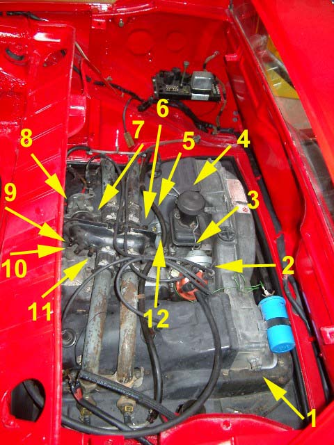
|
|
|
|
| SirAndy |
Jun 29 2003, 02:09 AM
Post
#5
|
|
Resident German Group: Admin Posts: 41,632 Joined: 21-January 03 From: Oakland, Kalifornia Member No.: 179 Region Association: Northern California |
Mark & Chris. thanks for the link to the diagram. altought it's for a 2.0 it does seem to make sense. i'll give it a try tomorrow ...
night night, Andy |
|
|
|
| sechszylinder |
Jun 29 2003, 03:05 AM
Post
#6
|
|
Member Group: Members Posts: 247 Joined: 9-April 03 From: /earth/europe/germany/berlin Member No.: 545 Region Association: None |
Hi Andy,
those small hoses are suited for iginition advance and retard. You have to connect the distributor (#3 in your diagram, Frühdose) to the throttle body (ignition advance) . Most of the 1,7 L throttle bodies don't have a connetor for ignition retard, so can leave (#2, Spätdose) open. If you have both ports on your throttle body, the upper connector goes to #3 and the lower connector (behind the thottle flap) goes to #2. (IMG:http://www.embeddedmedia.de/zuend.jpg) The intake of AAR goes to the air cleaner. Exit of AAR goes to the air plenum. hope this helps a little ... Benno |
|
|
|
| Drums66 |
Jun 29 2003, 09:30 AM
Post
#7
|
|
914 Rudiments Group: Members Posts: 5,321 Joined: 15-January 03 From: Coronado,Cali Member No.: 151 Region Association: Southwest Region |
Andy, that picture is a 1.7 Diagram
|
|
|
|
| Drums66 |
Jun 29 2003, 10:17 AM
Post
#8
|
|
914 Rudiments Group: Members Posts: 5,321 Joined: 15-January 03 From: Coronado,Cali Member No.: 151 Region Association: Southwest Region |
Andy, on second take that looks like a mixture of different componants(1.8 throttle body?) (IMG:style_emoticons/default/confused24.gif)
|
|
|
|
| Bleyseng |
Jun 29 2003, 12:27 PM
Post
#9
|
|
Aircooled Baby! Group: Members Posts: 13,034 Joined: 27-December 02 From: Seattle, Washington (for now) Member No.: 24 Region Association: Pacific Northwest |
here is a 1.7 hose diagram-
Make sure the oil filler has a PVC valve that the hose connects to, there is engine vacuum on that line and the PCV valve regulates it. The MPS needs a clean hose without any other hoses attached or split off from it. Plug the decel hose ports Get a 45mm Bus/Vanagon Throttle Body instead of the 1.7/1.8 40mm one. I have one if you need it, to get more air in. Make sure you hook up the vacuum adv hose off the Adv can on the distributor to the low pressure side of the throttle body. That means before the throttle plate. The vaccum retard hose is attached to the high pressure port under the throttle plate. Attached image(s) 
|
|
|
|
|
1 User(s) are reading this topic (1 Guests and 0 Anonymous Users)
0 Members:

|
Lo-Fi Version | Time is now: 12th May 2024 - 05:08 AM |
Invision Power Board
v9.1.4 © 2024 IPS, Inc.