|
|
|
Porsche, and the Porsche crest are registered trademarks of Dr. Ing. h.c. F. Porsche AG.
This site is not affiliated with Porsche in any way. Its only purpose is to provide an online forum for car enthusiasts. All other trademarks are property of their respective owners. |
|
|

  |

| SKL1 |
 Apr 22 2017, 06:12 PM Apr 22 2017, 06:12 PM
Post
#41
|
|
Senior Member  Group: Members Posts: 1,597 Joined: 19-February 11 From: north Scottsdale Member No.: 12,732 Region Association: Upper MidWest |
OK, I'm wiring this thing up and don't want to fry anything. Looking at my set up, the big red wire from the battery AND the slightly smaller red wire from the wiring loom go to one of the big studs on the Ford part, correct?
Then a big red wire goes from the other big stud on the Ford part to the starter along with the big wire from the battery. Then the yellow ignition wire goes on the little stud? 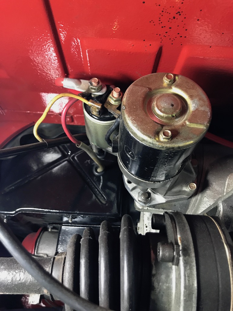 |
   |

 
|
| Spoke |
Apr 22 2017, 10:22 PM
Post
#42
|
|
Jerry Group: Members Posts: 6,972 Joined: 29-October 04 From: Allentown, PA Member No.: 3,031 Region Association: None |
QUOTE(SKL1 @ Apr 22 2017, 08:12 PM)  OK, I'm wiring this thing up and don't want to fry anything. Looking at my set up, the big red wire from the battery AND the slightly smaller red wire from the wiring loom go to one of the big studs on the Ford part, correct? Then a big red wire goes from the other big stud on the Ford part to the starter along with the big wire from the battery. Then the yellow ignition wire goes on the little stud? It's hard to say which wires go where since several schematics were shown on the previous page. Which one are you following? Please re-post the schematic you're following. The schematic is your connection guide. Follow your schematic and you will complete the installation correctly. Make a paper copy of your schematic and as you make connections, trace the wires out on the schematic with a colored pen/pencil/crayon so you know you've made that connection. When all wires are colored in then you are done. The heavy wire to from the battery must go directly to the starter, not the relay. This wire is the most crucial wire for the starter to have maximum power transfer. A wire the size of the wire going to the bendix can be run from the battery cable at the starter to the relay. The relay current in the bendix should be relatively low (less than 10A) whereas the starter current could be 100 to 200+ amps. As Mark mentioned, something about this installation seems to be overly complicated for a relatively simple modification. |
|
|
|
| SKL1 |
Apr 22 2017, 11:25 PM
Post
#43
|
|
Senior Member Group: Members Posts: 1,597 Joined: 19-February 11 From: north Scottsdale Member No.: 12,732 Region Association: Upper MidWest |
Spoke- all the different schematics do get confusing, but I planned on Mark's. Just didn't know what to do with the other red wire from the loom that is currently on the starter solenoid with the big red wire from the battery.
Hope Mark chimes in again to help someone getting more confused the more he goes through this thread!!! (I've enlarged the hole on the new bracket to mount on the lower starter bolt like Mark suggests. None of the new wires will need to go very far.) |
|
|
|
| euro911 |
Apr 23 2017, 02:06 AM
Post
#44
|
|
Retired & living the dream. God help me if I wake up! Group: Members Posts: 8,845 Joined: 2-December 06 From: So.Cal. & No.AZ (USA) Member No.: 7,300 Region Association: Southern California |
The yellow wire comes from the ignition switch and connects to the small post on the Ford relay, marked 'S'
The smaller gauge red wire comes from the alternator and sends the charging voltage to the battery. It needs to stay connected to the '+' battery cable, so connect it to one of the large posts on the Ford relay along with the '+' cable from the battery (as shown in all of the diagrams posted). There is some disagreement on how to connect the remaining large gauge cable from the other large post on the Ford relay to the starter and the smaller gauge wire to the starter solenoid ... take your pick ... either method will work. |
|
|
|
| Mark Henry |
Apr 23 2017, 06:25 AM
Post
#45
|
|
that's what I do! Group: Members Posts: 20,065 Joined: 27-December 02 From: Port Hope, Ontario Member No.: 26 Region Association: Canada |
Ok...I have a solenoid in my bus and my /6 and trans on my lift cart, I'll do a complete install today and post a how to.
|
|
|
|
| Spoke |
Apr 23 2017, 07:46 PM
Post
#46
|
|
Jerry Group: Members Posts: 6,972 Joined: 29-October 04 From: Allentown, PA Member No.: 3,031 Region Association: None |
Here's the entire starter circuit schematic with the Ford relay. There should only be 5 wires.
Wire Connections: Existing 914 Wires: o The heavy red cable from the battery goes directly to the large lug on the starter. o The smaller red cable from the alternator goes directly to the large lug on the starter. o The yellow wire from the ignition switch goes to the "S" terminal of the Ford relay New Wires: o Red (or any color) wire 12-16GA goes from large lug on the starter to one of the big lugs on the Ford relay; either lug will work. o Black (or any color wire 12-16GA goes from one of the big lugs on the Ford relay to the Bendix Coil on the starter. either big lug on the Ford relay will work. Attached thumbnail(s) 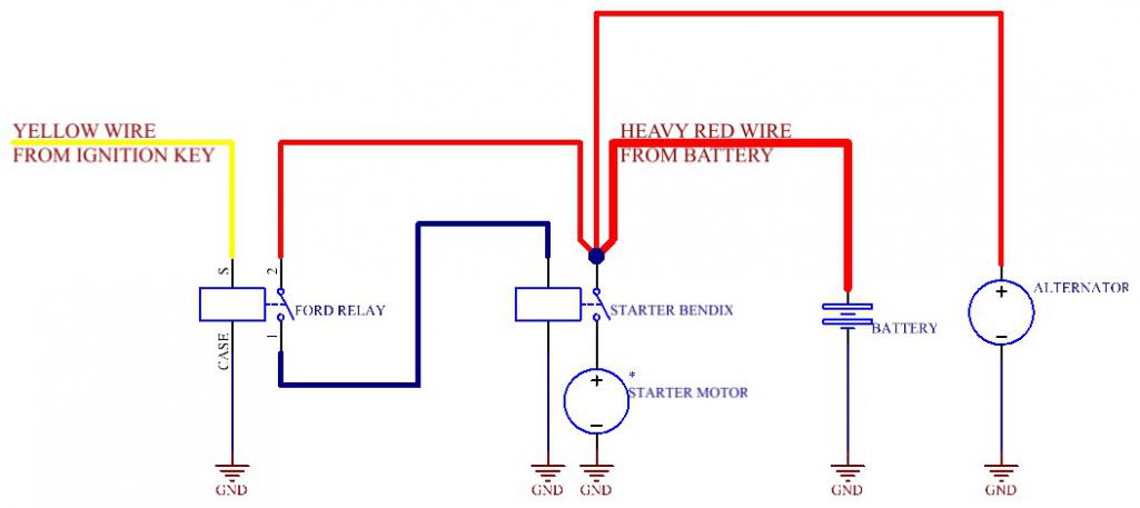
|
|
|
|
| Mark Henry |
Apr 24 2017, 06:56 AM
Post
#47
|
|
that's what I do! Group: Members Posts: 20,065 Joined: 27-December 02 From: Port Hope, Ontario Member No.: 26 Region Association: Canada |
Enough of the armchair experts....my way of installing the Ford solenoid.
http://www.914world.com/bbs2/index.php?showtopic=308904 |
|
|
|
| euro911 |
Apr 24 2017, 07:24 PM
Post
#48
|
|
Retired & living the dream. God help me if I wake up! Group: Members Posts: 8,845 Joined: 2-December 06 From: So.Cal. & No.AZ (USA) Member No.: 7,300 Region Association: Southern California |
The starting issue stems from the ignition switch circuit (complete round-trip with the yellow wire). All the diagrams that have been posted address that issue.
The reason for utilizing a Ford relay is that it takes less current on the primary coil windings to complete the connection between the contacts (large studs) when energized. Those contacts are specifically designed to switch heavy amperage (current). Whether one connects the battery cable directly to the starter's large stud or runs it through the relay, both methods cure the problem ... in other words, there's more than one way to skin a cat. Retired electrical engineer (aka: armchair expert) (IMG:style_emoticons/default/rolleyes.gif) |
|
|
|
|
1 User(s) are reading this topic (1 Guests and 0 Anonymous Users)
0 Members:

|
Lo-Fi Version | Time is now: 19th April 2024 - 09:39 PM |
Invision Power Board
v9.1.4 © 2024 IPS, Inc.