|
|
|
Porsche, and the Porsche crest are registered trademarks of Dr. Ing. h.c. F. Porsche AG.
This site is not affiliated with Porsche in any way. Its only purpose is to provide an online forum for car enthusiasts. All other trademarks are property of their respective owners. |
|
|

  |

| bbrock |
 May 13 2018, 09:07 PM May 13 2018, 09:07 PM
Post
#421
|
|
914 Guru  Group: Members Posts: 5,269 Joined: 17-February 17 From: Montana Member No.: 20,845 Region Association: Rocky Mountains |
QUOTE(KELTY360 @ May 13 2018, 05:52 PM)  Now, enough Westy love. (IMG:style_emoticons/default/mad.gif) Get back to work on your 914, Brent. BTW I may take you up on that driveway space. Still haven’t figured out my next stop. Stop by. Two moose were hanging out about 20 feet from the house an hour ago. So here's the rest of the progress for the day... or should I say, some progress and some tail chasing. I spent a fair amount of time stripping more undercoat and seam sealer to clean things up to repair that rust hole near the antenna mount. I cut out the cancer and treated the hole with phosphoric acid. 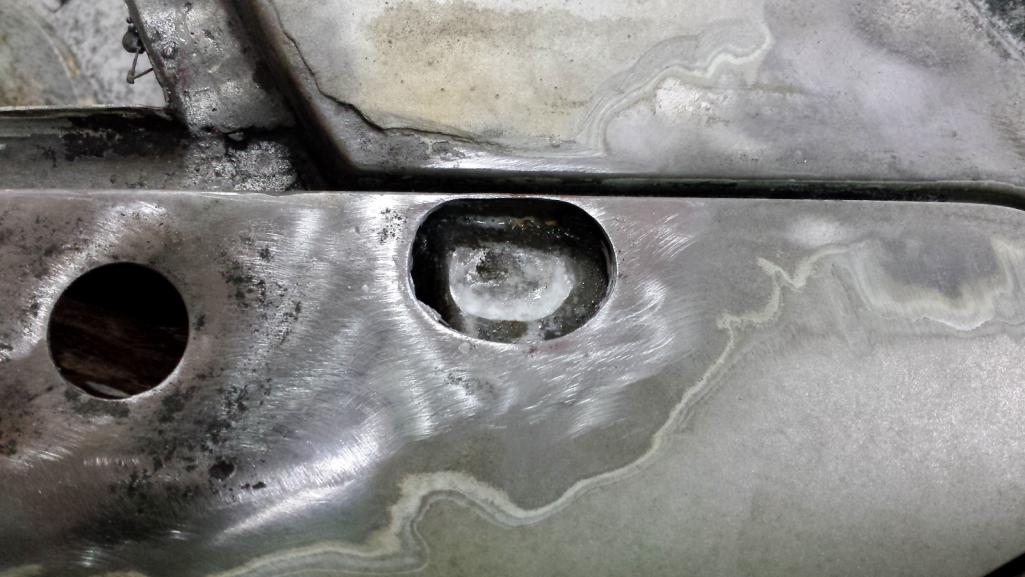 and the patch was welded, ground, and blended. Not too bad. 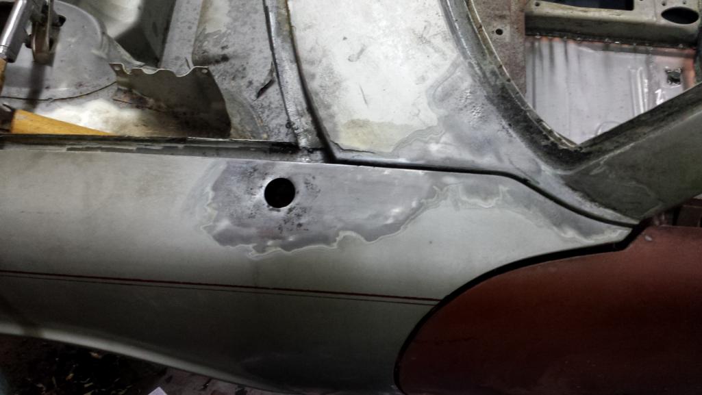 Then I went back to that channel in the corner near the antenna to grind down the final welds. I noticed a couple pinholes and blew out the bottom trying to fix them. Then I got pissed off and ripped out that section and cut a patch. I wasn't really happy with that repair anyway. The hole I zapped shut was really too big and the patch was brittle. I didn't take pics because it was just a repeat of the other side, only a much smaller piece. Here's the result with a temporary dusting of primer on it and that patch I did earlier. 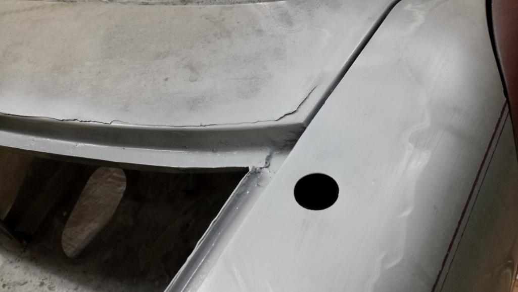 The next patch is going to be interesting. Stay tuned. (IMG:style_emoticons/default/bye1.gif) |
   |

 
|
| bbrock |
May 16 2018, 10:21 PM
Post
#422
|
|
914 Guru Group: Members Posts: 5,269 Joined: 17-February 17 From: Montana Member No.: 20,845 Region Association: Rocky Mountains |
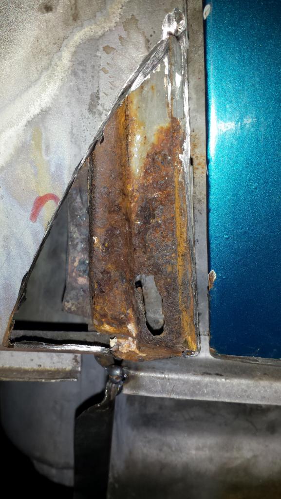
No progress to report but planning the next task and am would welcome advice so I hope I can explain it well enough. That next task is patching rust at the bottom rear of the front fender.
 The old door has a matching patch of rot, plus some brazing from the PO's body work. 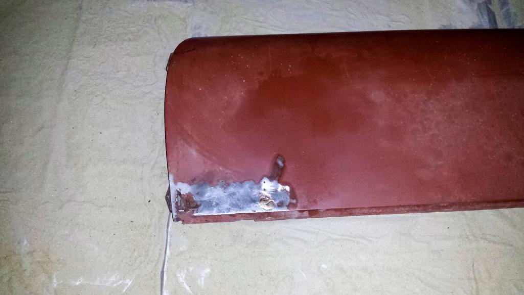 From the get-go of this project, that area had a narrow gap that I assumed (and still hope) is caused by the corrosion pushing the body lines together. The plan is to adjust the gaps as part of the rust repair so the first step was to fit the replacement door and see where things fit. After a lot of fiddling, I got the hinges adjusted for the best fit I could get. The front fender and door line up pretty well with all the surfaces matching along the same straight plane. The rear quarter and door look good at the top but I discovered a problem that the puffiness of the rot in the front of the door and fender was masking. The rear quarter meets the lower part of the door with about a 2 mm offset in the planes. 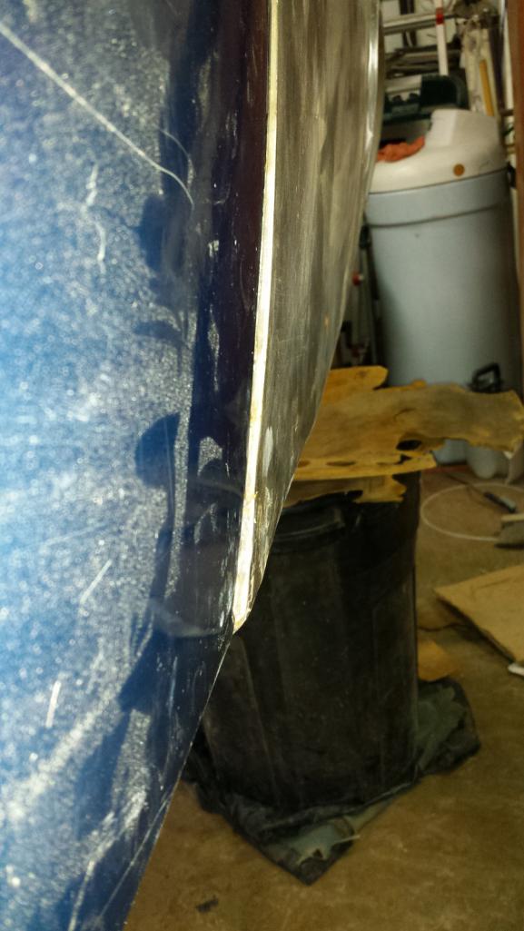 Believe it or not, I'm not too worried about that and here's why. 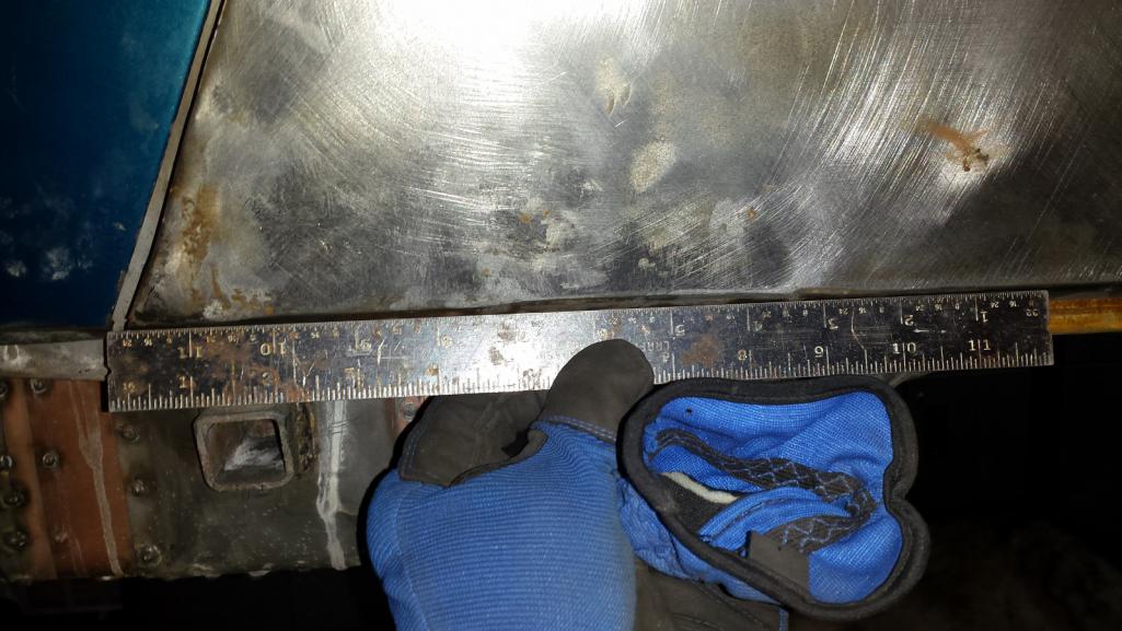 I bullocksed the repair on the bottom of that quarter and it has to be redone. The problem was that I cut and welded the patch along that bottom bend and didn't think about how welding would shrink the gap. The upshot is that the body line along the bottom is shit and has to be cut out and redone. This time, I have a couple of spare doors that happen to have the exact profile I need so I'm going to cannibalize skin off the old door to create a new patch. While I"m doing that, Ill be able to fix the f'd up alignment with the door. The bigger question is about gaps at the front of the door. Here are pics with gap measurements in millimeters. 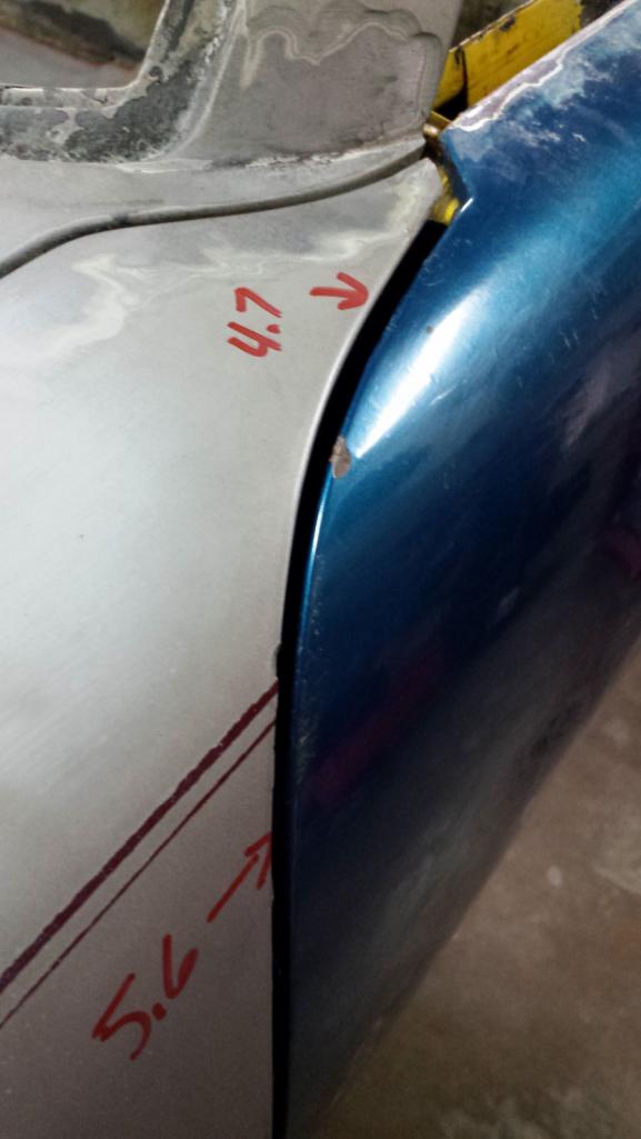 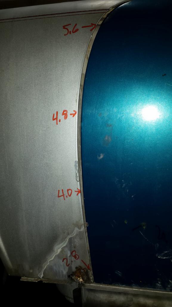 As near as I can tell, it must be normal for the gap to widen (almost 1 mm) at the curve between the top of the door and side because I can't think of what problem would cause that. I'm tempted to weld a little material along the edge to even out that gap. I don't really have a plan for the gap at the bottom of the hinge post but hoping one emerges after I cut it open for the rust repair. |
|
|
|
| bbrock |
May 17 2018, 09:44 AM
Post
#423
|
|
914 Guru Group: Members Posts: 5,269 Joined: 17-February 17 From: Montana Member No.: 20,845 Region Association: Rocky Mountains |
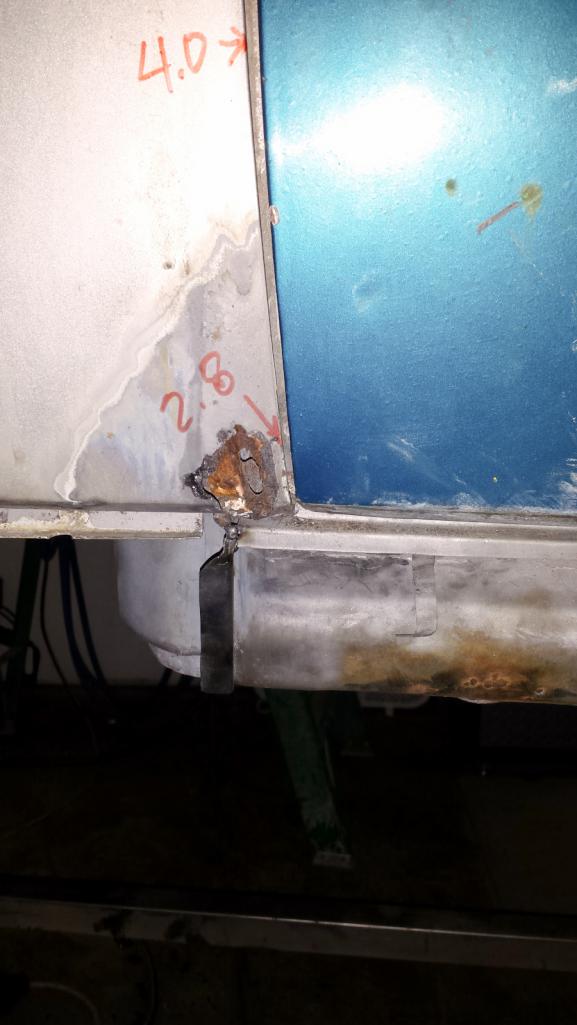
I did a bit of cutting this morning and more measuring to figure out this gap thing. This is the bottom of the A-pillar with the rotted fender skin removed. I confirmed that the gap remains a steady 4mm down to where the rust begins and then tapers to about 2mm at the very bottom. I'm feeling like somehow the corrosion swelled the metal or allowed it to move to close that gap, or maybe the gap was always narrow there. Either way, it should be easy to correct.
 I'm stilled a bit confused by the wide gap at the top of the door. I need to play with those hinge adjustments more to see if there that can help. I did think through possibilities of bent or shrunk frame members, but my chassis measurements are spot on and because the doors bolt to the A-pillar, that gap should remain constant even if the pillar moved. I also need to get both sides stripped to bare metal to make sure I'm aligning the actual panels and not body filler. |
|
|
|
| bbrock |
May 21 2018, 10:27 PM
Post
#424
|
|
914 Guru Group: Members Posts: 5,269 Joined: 17-February 17 From: Montana Member No.: 20,845 Region Association: Rocky Mountains |
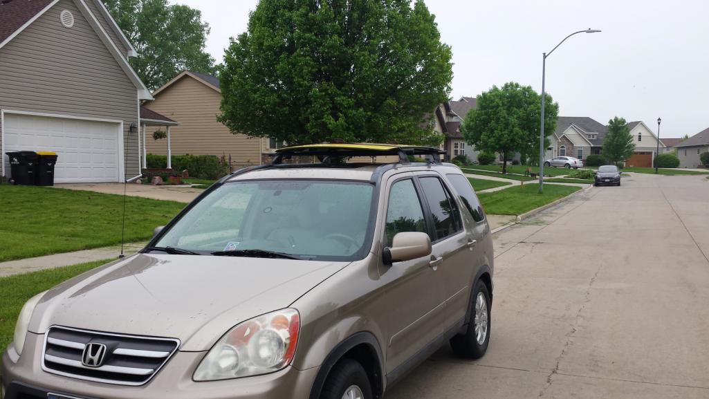
Heading home from Iowa in the morning with a nice 914 trunk lid strapped to the roof. I had a very generous offer from rhodyguy for another lid that needed some minor repair but opted for this one because I feel like I've patched enough holes and not confident in my skills to handle a trunk lid patch.
 |
|
|
|
| mb911 |
May 22 2018, 09:13 AM
Post
#425
|
|
914 Guru Group: Members Posts: 7,742 Joined: 2-January 09 From: Burlington wi Member No.: 9,892 Region Association: Upper MidWest |
QUOTE(bbrock @ May 16 2018, 08:21 PM) No progress to report but planning the next task and am would welcome advice so I hope I can explain it well enough. That next task is patching rust at the bottom rear of the front fender. The old door has a matching patch of rot, plus some brazing from the PO's body work. From the get-go of this project, that area had a narrow gap that I assumed (and still hope) is caused by the corrosion pushing the body lines together. The plan is to adjust the gaps as part of the rust repair so the first step was to fit the replacement door and see where things fit. After a lot of fiddling, I got the hinges adjusted for the best fit I could get. The front fender and door line up pretty well with all the surfaces matching along the same straight plane. The rear quarter and door look good at the top but I discovered a problem that the puffiness of the rot in the front of the door and fender was masking. The rear quarter meets the lower part of the door with about a 2 mm offset in the planes. Believe it or not, I'm not too worried about that and here's why. I bullocksed the repair on the bottom of that quarter and it has to be redone. The problem was that I cut and welded the patch along that bottom bend and didn't think about how welding would shrink the gap. The upshot is that the body line along the bottom is shit and has to be cut out and redone. This time, I have a couple of spare doors that happen to have the exact profile I need so I'm going to cannibalize skin off the old door to create a new patch. While I"m doing that, Ill be able to fix the f'd up alignment with the door. The bigger question is about gaps at the front of the door. Here are pics with gap measurements in millimeters. As near as I can tell, it must be normal for the gap to widen (almost 1 mm) at the curve between the top of the door and side because I can't think of what problem would cause that. I'm tempted to weld a little material along the edge to even out that gap. I don't really have a plan for the gap at the bottom of the hinge post but hoping one emerges after I cut it open for the rust repair. Yes I believe it is fairly normal. I will be welding in the gaps on mine to make it cleaner. |
|
|
|
| bbrock |
May 22 2018, 09:19 PM
Post
#426
|
|
914 Guru Group: Members Posts: 5,269 Joined: 17-February 17 From: Montana Member No.: 20,845 Region Association: Rocky Mountains |
QUOTE(mb911 @ May 22 2018, 09:13 AM) Yes I believe it is fairly normal. I will be welding in the gaps on mine to make it cleaner. Good to know. I made some adjustments that got the top area tighter and will have one more adjustment to try. I'll still need to do some welding but maybe not as much. |
|
|
|
| bbrock |
May 26 2018, 10:31 PM
Post
#427
|
|
914 Guru Group: Members Posts: 5,269 Joined: 17-February 17 From: Montana Member No.: 20,845 Region Association: Rocky Mountains |
Spent time during the week working on the driver's door gaps some more. I ended up grinding out the holes for the hinge bolts a little larger to allow more range of adjustment for the doors.
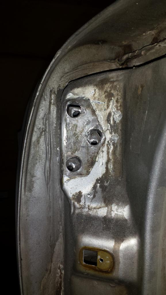 After that, I was able to better align the door with the fender and got most of the gap down to about 4.3mm. I'll still have to weld a bit to regap some, but I'm much closer to the end goal now. I had other projects to work on today so didn't get to the car until about 4 pm this afternoon. I made a start on tackling this mess. (IMG:http://www.914world.com/bbs2/uploads/post-20845-1526571351_thumb.jpg) This required a lot of dental work to cut the rotted fender skin where it crimps around a flange on the A-pillar, and cutting out the rusted portion of that flange. After cutting everything out, it got a good treatment with the KleanStrip version of Ospho. Here it is ready to rebuild the inner structure that the skin crimps over. 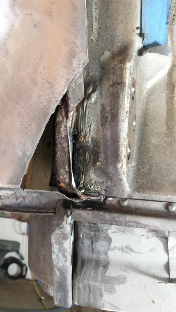 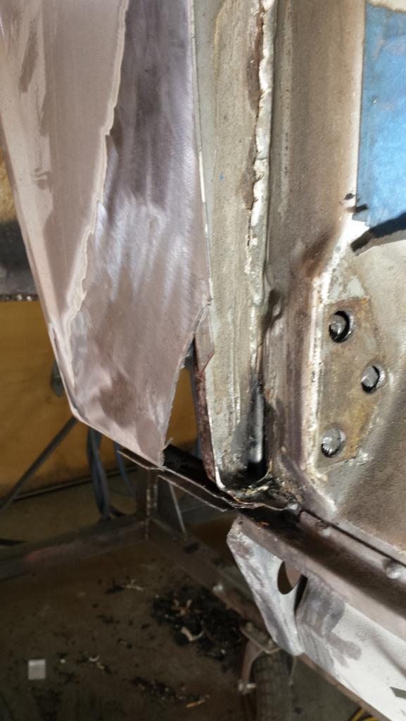 Amazing how long it took to make this pathetic looking scrap of metal to repair the structure. 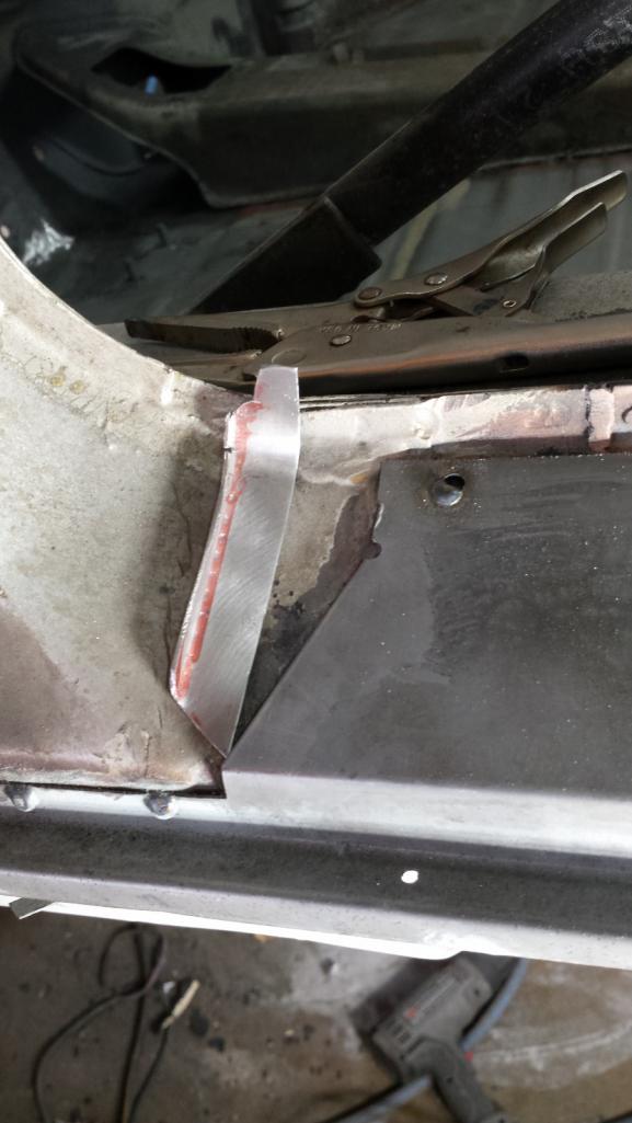 It didn't take long to weld the little scrap in and grind it down. This will all get buried under the skin and seam sealer, but I still took the time to restore the original profile and look. 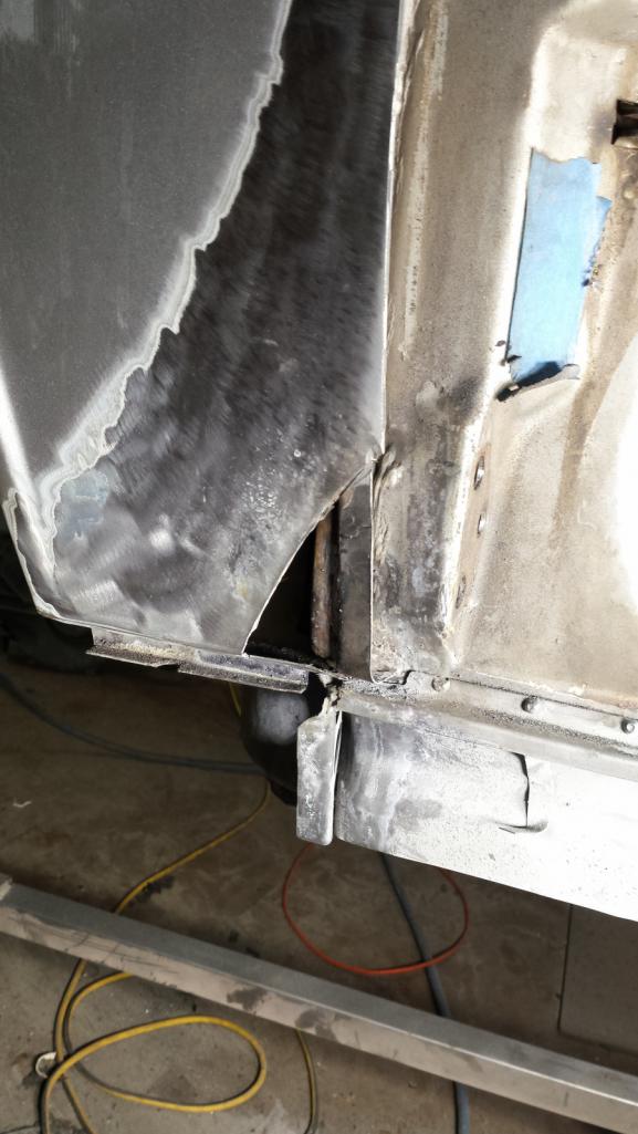 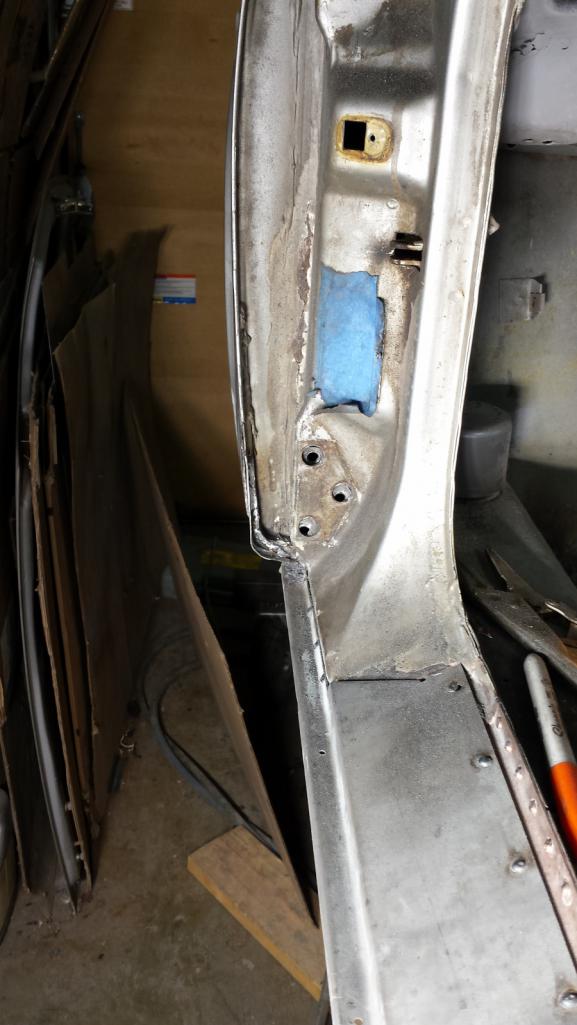 Tomorrow I'll see if I can pull off repairing the skin. Wish me luck! (IMG:style_emoticons/default/blink.gif) |
|
|
|
| tygaboy |
May 27 2018, 07:13 AM
Post
#428
|
|
914 Guru Group: Members Posts: 5,810 Joined: 6-October 15 From: Petaluma, CA Member No.: 19,241 Region Association: Northern California |
Luck... ha and peshaw!
I'm sending you good vibrations for: - clean and solid parent metal (IMG:style_emoticons/default/cheer.gif) - perfect welder settings (IMG:style_emoticons/default/welder.gif) - not welding the wire to the tip (particularly when working in those hard to reach areas) (IMG:style_emoticons/default/smilie_pokal.gif) - patch pieces that turn out nicely on the first attempt (IMG:style_emoticons/default/smash.gif) - no weld spatter sparks ending up in your ear (IMG:style_emoticons/default/pray.gif) Now get back out there! And keep up the great work! (and I promise, that rear window will get packed and shipped at some point!) |
|
|
|
| bbrock |
May 27 2018, 11:17 PM
Post
#429
|
|
914 Guru Group: Members Posts: 5,269 Joined: 17-February 17 From: Montana Member No.: 20,845 Region Association: Rocky Mountains |
Good, Good, Good! Good Vibrations! (IMG:style_emoticons/default/piratenanner.gif)
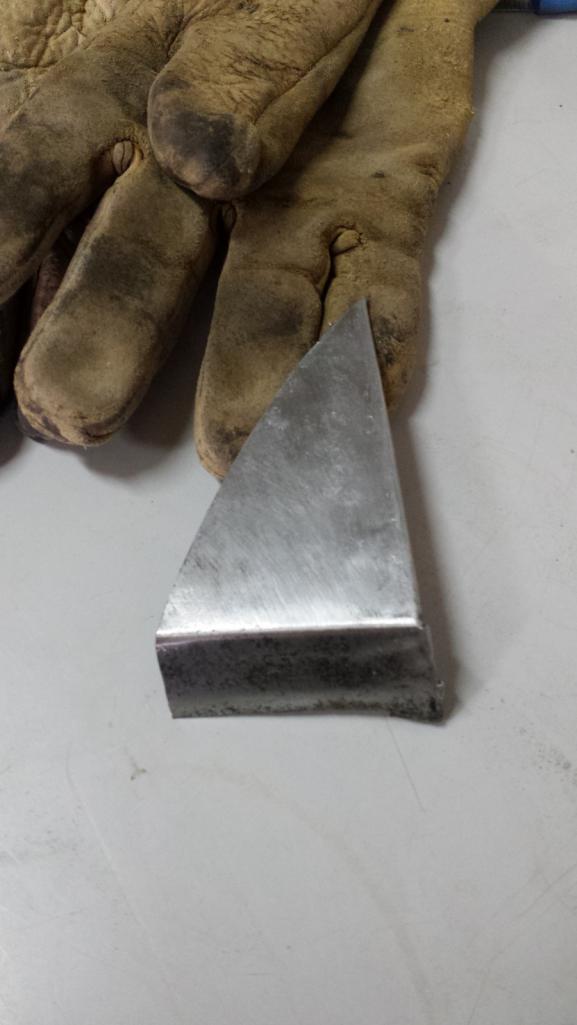
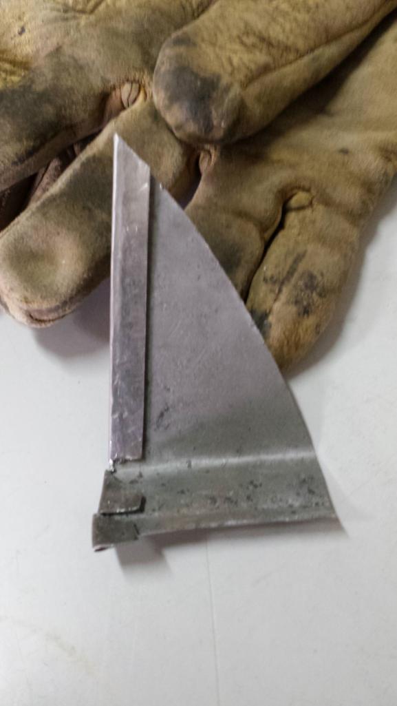
I don't know what kind of Mojo you were sending me Chris, but I'll take some more please (IMG:style_emoticons/default/beerchug.gif) What a rewarding day! I started the day with a lot of trepidation because I knew I was in above my head with the task ahead. First up was fitting up the door again to see what adjustments were needed on that inner structure I did yesterday. As expected, there was some, but not bad, just a little bulge below the bottom body line.  To fix it, I just cut across the bottom crease line. 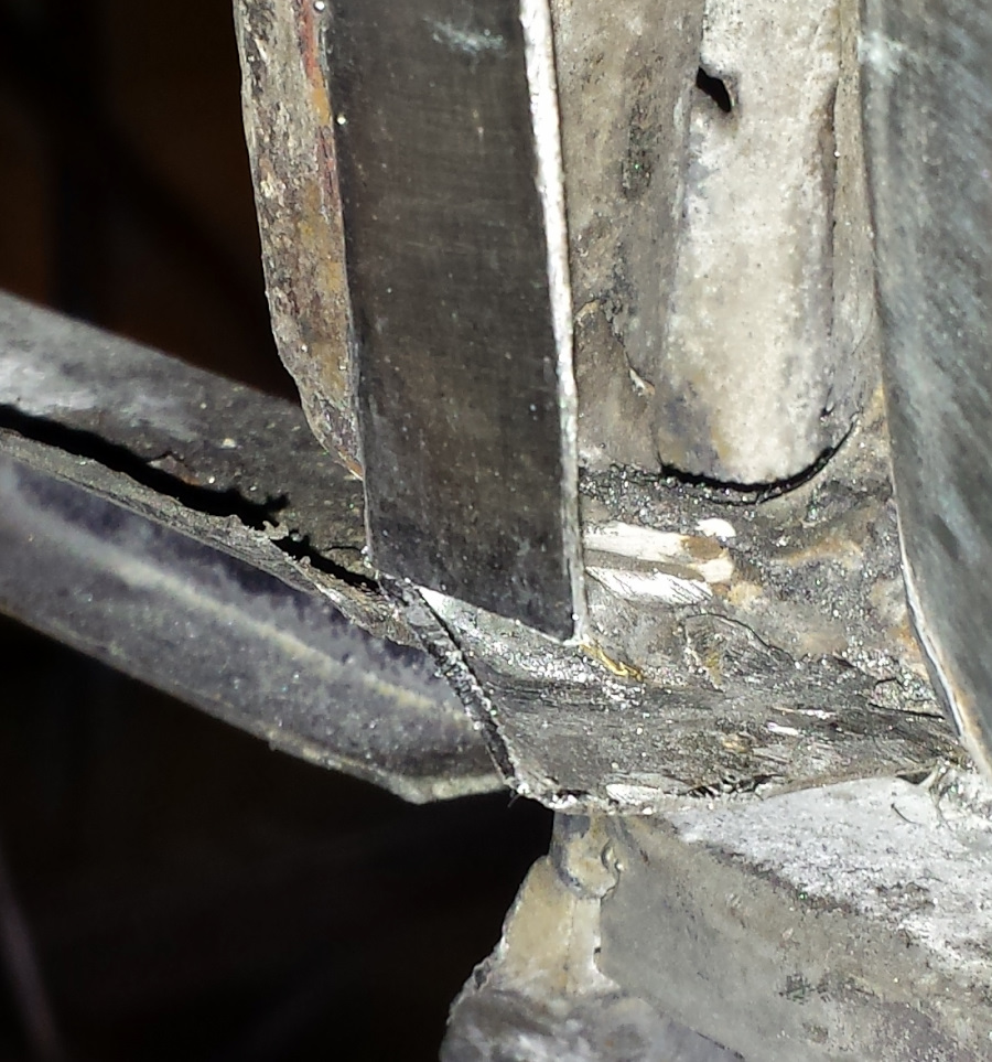 Then tapped the bulge up into the right line. Amazing how ony 1mm of extra material can throw things out of whack. 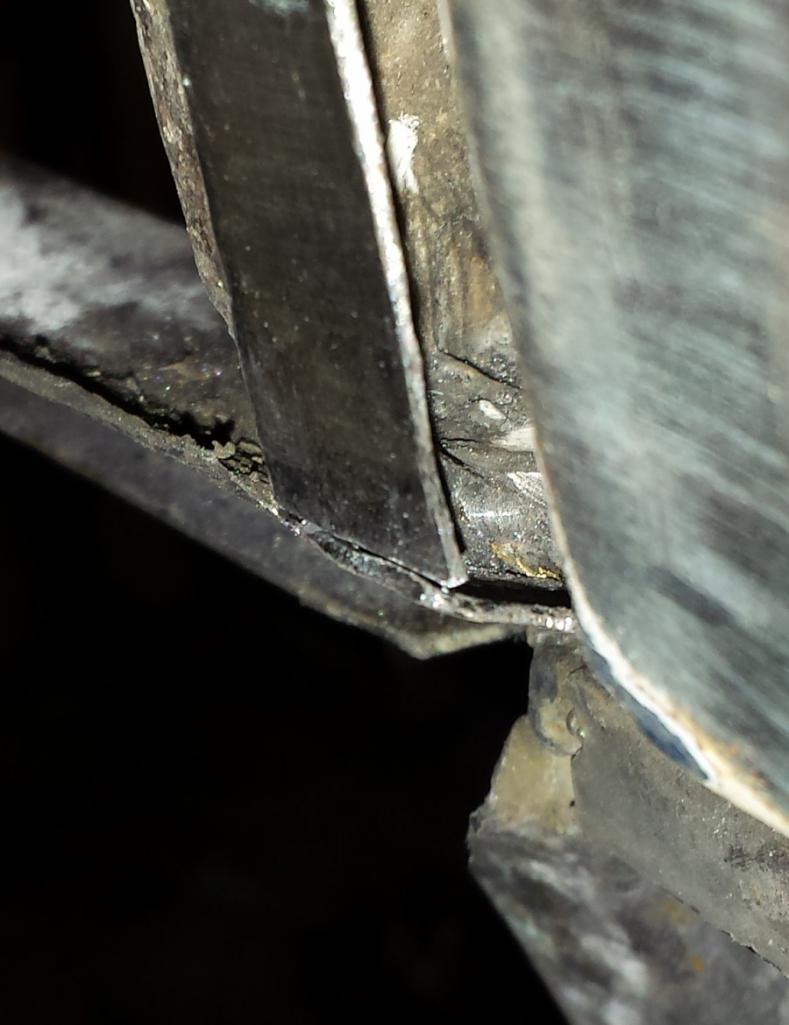 Then trim off the access and glue it up with a little high temperature metal adhesive. 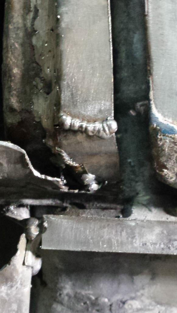 A little grinding and final adjustment, and Bob's your uncle. It still looks a little out of line in this pic, but it isn't. 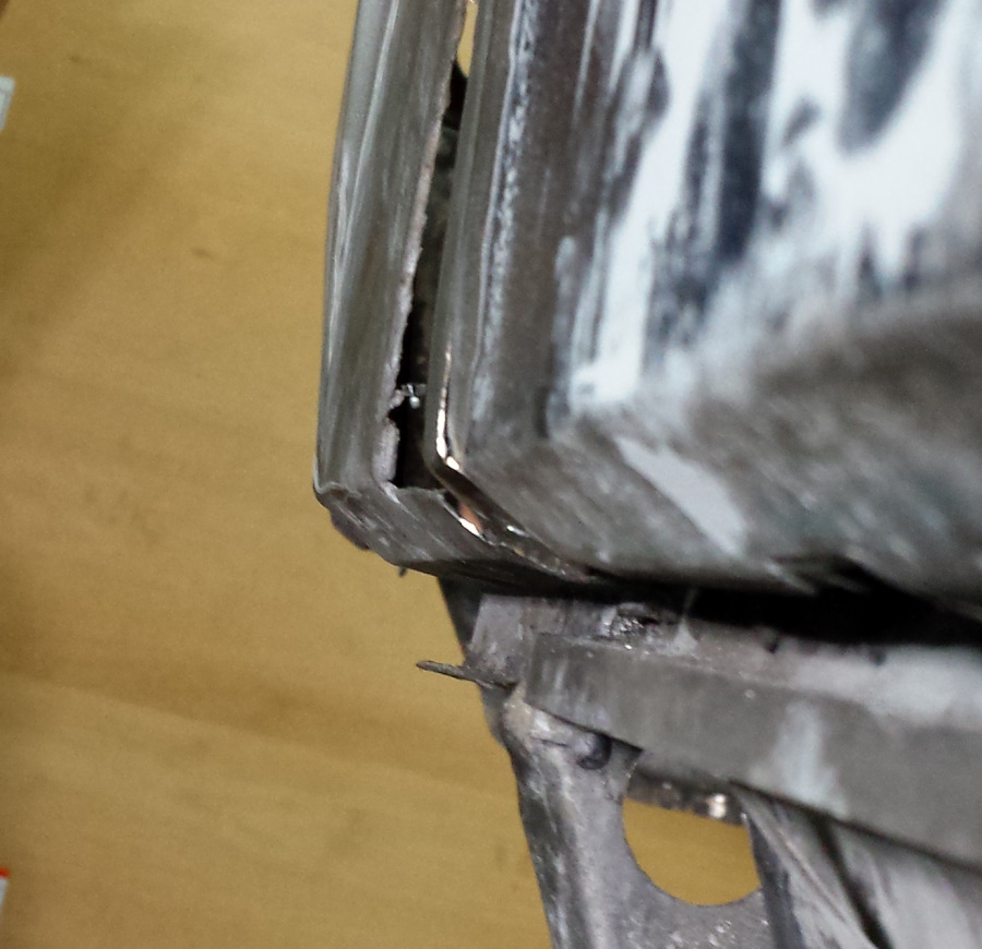 Now for the fun stuff. First, I made a pattern for the skin patch using tracing paper. I started by tracing the existing gap lines, the bottom crease line, and outline of the cutout for the patch. Then I shifted the pattern over so the partial fender side gap line was lined up with the door gap side. That let me trace the front edge of the patch so it would follow the door contour. 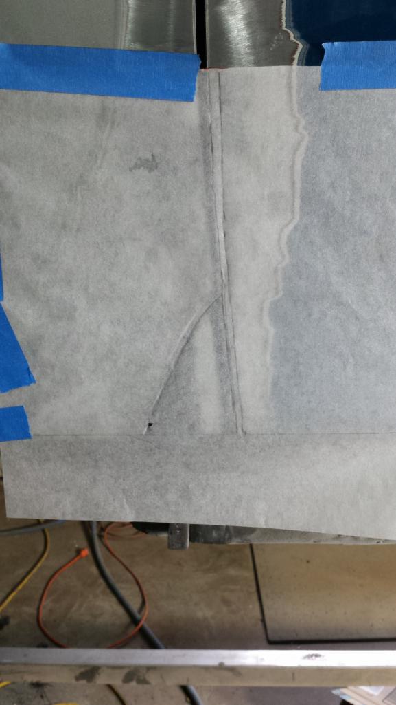 I retraced the lines with black marker. Solid for cut lines and dashed for bend lines. Here it is repositioned in correct alignment. 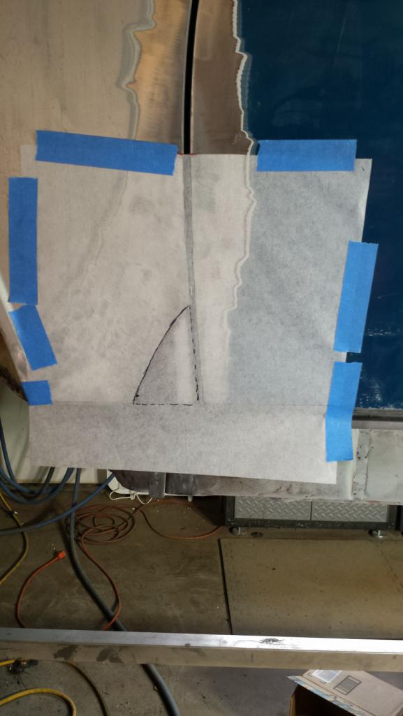 I cut the patch piece out of the original door since it already has the right contour, including the bends at the bottom. 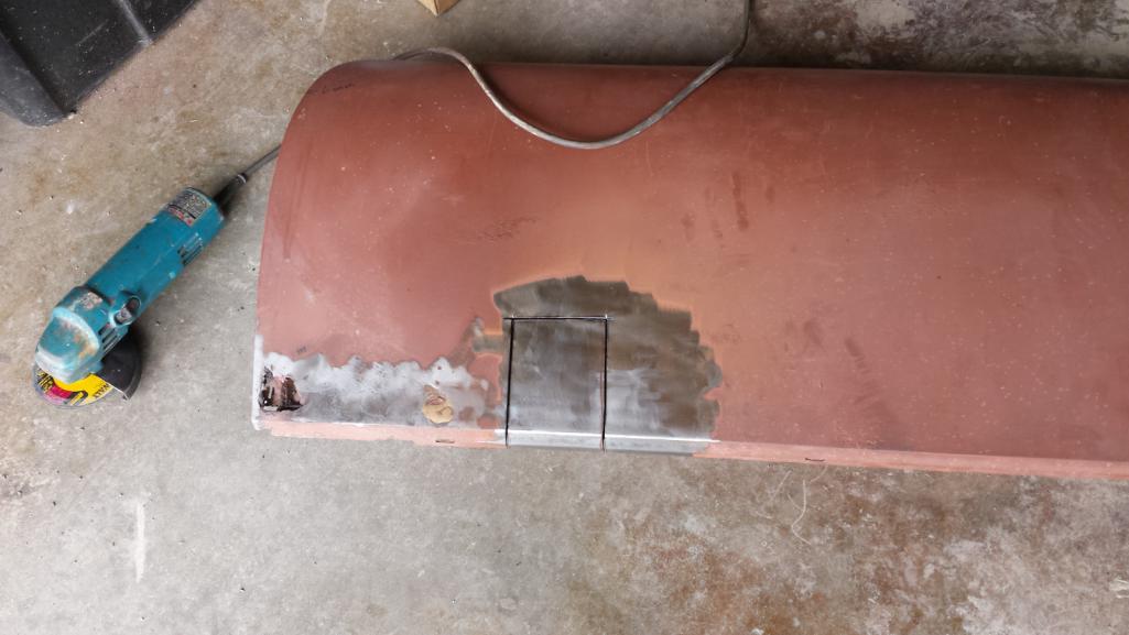 Now for a couple hours making the patch. |
|
|
|
| bbrock |
May 27 2018, 11:24 PM
Post
#430
|
|
914 Guru Group: Members Posts: 5,269 Joined: 17-February 17 From: Montana Member No.: 20,845 Region Association: Rocky Mountains |
I used the pattern to cut it out and left 12mm on the door side to bend over a 10mm flange that crimps over that inner structure flange repaired yesterday. There is a subtle curve on that edge so the flange had to be bent a little at a time, then hammered over onto itself, the pried open enough so it could slip tightly over the structure flange. Tedious work just to get the that point,
  Then repeatedly fitting it on, grinding a little off the back edge, refitting, more grinding, again and again to sneak up on the perfect fit. The crimp fit is so tight there is no need for clamps. 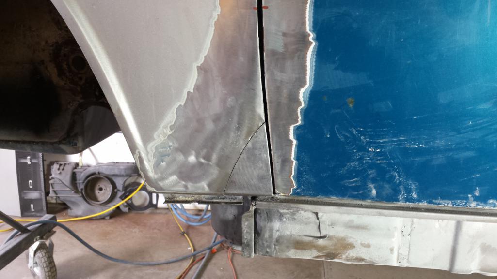 A new scar that needs to heal. 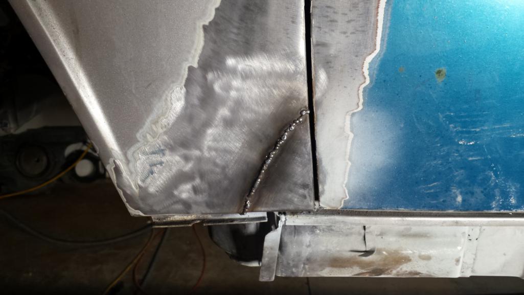 And here's the end result. Not too shabby! (IMG:style_emoticons/default/aktion035.gif) 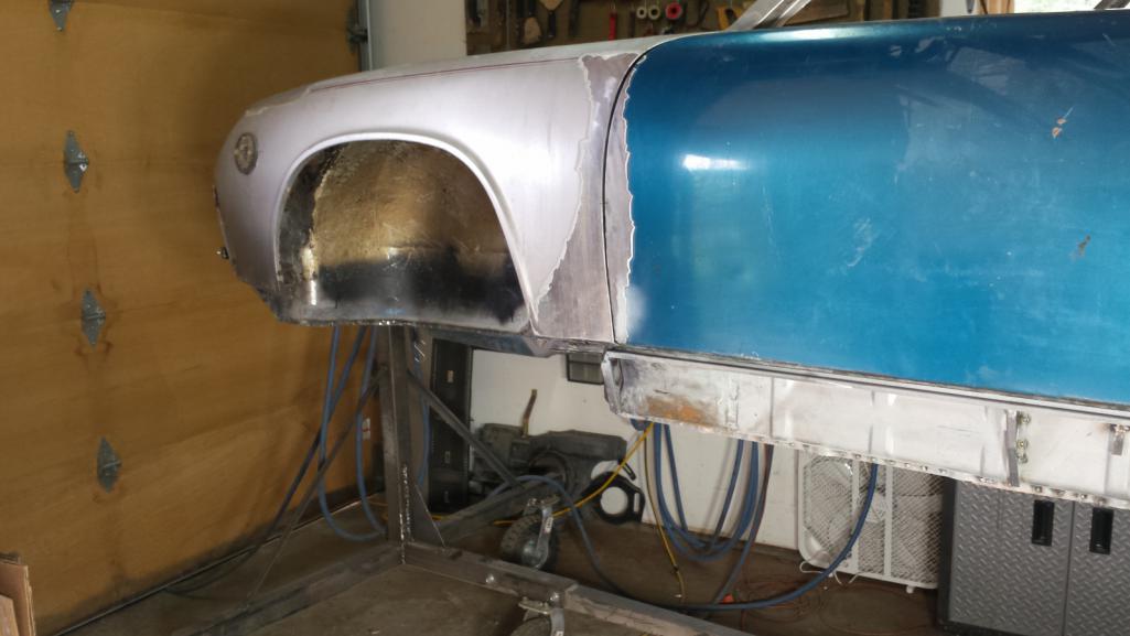 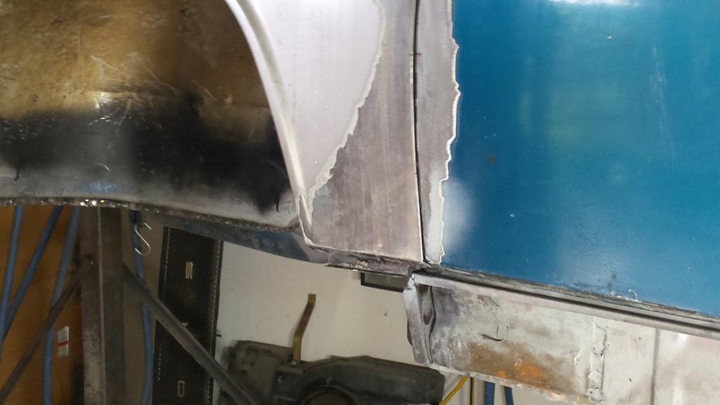 There is still a bit of house keeping to do behind the door, but I want to finish the rear quarter repairs before pulling the door off again. I have an idea for making those adjustments that will be easier than a full repatch. That's on the agenda for tomorrow. |
|
|
|
| falcor75 |
May 27 2018, 11:55 PM
Post
#431
|
|
Senior Member Group: Members Posts: 1,579 Joined: 22-November 12 From: Sweden Member No.: 15,176 Region Association: Scandinavia |
Great work, I'm always impressed with the patience of a good repair piece. Is it just me or could you run your welder with less wire feed to reduce the height of the spotwelds and spend less time on grinding? You dont want balls of metal ontop of the weld, they should float out a bit more.
|
|
|
|
| bbrock |
May 28 2018, 12:07 AM
Post
#432
|
|
914 Guru Group: Members Posts: 5,269 Joined: 17-February 17 From: Montana Member No.: 20,845 Region Association: Rocky Mountains |
QUOTE(falcor75 @ May 27 2018, 11:55 PM) Great work, I'm always impressed with the patience of a good repair piece. Is it just me or could you run your welder with less wire feed to reduce the height of the spotwelds and spend less time on grinding? You dont want balls of metal ontop of the weld, they should float out a bit more. Yeah, I was having fits with the settings today. I dialed back the feed and it helped some but I'm a little worried I have a diode out again as the welder just seems weak. I'm going to mess with it tomorrow and see if I can sort it out. I have easy grind spooled up for this job so at least grinding didn't take long. |
|
|
|
| tygaboy |
May 28 2018, 06:40 AM
Post
#433
|
|
914 Guru Group: Members Posts: 5,810 Joined: 6-October 15 From: Petaluma, CA Member No.: 19,241 Region Association: Northern California |
Brent - Excellent! You're right to be pleased with that repair! Super-duper awesomeness, for sure. (IMG:style_emoticons/default/smilie_pokal.gif)
Congrats and more of the same. Can't wait to see the next steps. And here come some more focused vibes re: welder settings: (IMG:style_emoticons/default/welder.gif) (IMG:style_emoticons/default/welder.gif) (IMG:style_emoticons/default/welder.gif) |
|
|
|
| mb911 |
May 28 2018, 07:30 AM
Post
#434
|
|
914 Guru Group: Members Posts: 7,742 Joined: 2-January 09 From: Burlington wi Member No.: 9,892 Region Association: Upper MidWest |
Looking good. Ironically i didn't need to repair that area on mine but the flares must have helped..
|
|
|
|
| bbrock |
May 28 2018, 09:20 AM
Post
#435
|
|
914 Guru Group: Members Posts: 5,269 Joined: 17-February 17 From: Montana Member No.: 20,845 Region Association: Rocky Mountains |
@#$K!!!
Well, I just ran some test welds and I'm pretty sure the diodes on the welder are burned out again. (IMG:style_emoticons/default/headbang.gif) (IMG:style_emoticons/default/headbang.gif) (IMG:style_emoticons/default/headbang.gif) I tested butt welding some scraps of 20 gauge and the chart settings of Voltage = 1 and Wire Speed = 6 just sputter and put a little ball on top of the gap. The only acceptable (but not great) weld I could get was cranking both the voltage and wire speed full up. That should have blown holes through the metal like a canon. I'm going to order a new set of diodes and capacitors but muddle through the repairs today with what I have. I understand having to replace diodes on a 30 year old welder, but this last set is less than a year old although probably saw as much welding as the old set. But still, they shouldn't be burning out like this. (IMG:style_emoticons/default/confused24.gif) Very frustrating! (IMG:style_emoticons/default/blowup.gif) |
|
|
|
| mb911 |
May 28 2018, 09:46 AM
Post
#436
|
|
914 Guru Group: Members Posts: 7,742 Joined: 2-January 09 From: Burlington wi Member No.: 9,892 Region Association: Upper MidWest |
QUOTE(bbrock @ May 28 2018, 07:20 AM) @#$K!!! Well, I just ran some test welds and I'm pretty sure the diodes on the welder are burned out again. (IMG:style_emoticons/default/headbang.gif) (IMG:style_emoticons/default/headbang.gif) (IMG:style_emoticons/default/headbang.gif) I tested butt welding some scraps of 20 gauge and the chart settings of Voltage = 1 and Wire Speed = 6 just sputter and put a little ball on top of the gap. The only acceptable (but not great) weld I could get was cranking both the voltage and wire speed full up. That should have blown holes through the metal like a canon. I'm going to order a new set of diodes and capacitors but muddle through the repairs today with what I have. I understand having to replace diodes on a 30 year old welder, but this last set is less than a year old although probably saw as much welding as the old set. But still, they shouldn't be burning out like this. (IMG:style_emoticons/default/confused24.gif) Very frustrating! (IMG:style_emoticons/default/blowup.gif) I have never had a set burn out.. You have a 125 handler? |
|
|
|
| KELTY360 |
May 28 2018, 10:50 AM
Post
#437
|
|
914 Neferati Group: Members Posts: 5,186 Joined: 31-December 05 From: Pt. Townsend, WA Member No.: 5,344 Region Association: Pacific Northwest |
QUOTE(bbrock @ May 27 2018, 10:24 PM) I used the pattern to cut it out and left 12mm on the door side to bend over a 10mm flange that crimps over that inner structure flange repaired yesterday. There is a subtle curve on that edge so the flange had to be bent a little at a time, then hammered over onto itself, the pried open enough so it could slip tightly over the structure flange. Tedious work just to get the that point, Then repeatedly fitting it on, grinding a little off the back edge, refitting, more grinding, again and again to sneak up on the perfect fit. The crimp fit is so tight there is no need for clamps. A new scar that needs to heal. And here's the end result. Not too shabby! (IMG:style_emoticons/default/aktion035.gif) There is still a bit of house keeping to do behind the door, but I want to finish the rear quarter repairs before pulling the door off again. I have an idea for making those adjustments that will be easier than a full repatch. That's on the agenda for tomorrow. Look at that! (IMG:style_emoticons/default/smilie_pokal.gif) I saw that nasty section a couple of weeks ago and thought you really had your hands full. Great solution and execution. The other side will be a piece of cake. |
|
|
|
| Dion |
May 28 2018, 11:58 AM
Post
#438
|
|
RN Group: Members Posts: 2,926 Joined: 16-September 04 From: Audubon,PA Member No.: 2,766 Region Association: MidAtlantic Region |
Sorry to hear of the welder diode issues but
that repair patch job looks fantastic. Really nice Brent! Good homework on your part. I’m getting quite jealous. :-) |
|
|
|
| bbrock |
May 28 2018, 12:57 PM
Post
#439
|
|
914 Guru Group: Members Posts: 5,269 Joined: 17-February 17 From: Montana Member No.: 20,845 Region Association: Rocky Mountains |
QUOTE(KELTY360 @ May 28 2018, 10:50 AM) Look at that! (IMG:style_emoticons/default/smilie_pokal.gif) I saw that nasty section a couple of weeks ago and thought you really had your hands full. Great solution and execution. The other side will be a piece of cake. Thanks Dion and Marc! I remember the look on your face Marc when you looked at that and said, "How are you going to handle that?" I hope the other side will be a piece of cake but the rust is more extensive than this one. The skin patch should be about the same, but the structure repair will be more complicated. I made some more progress this morning. I wanted to address the alignment of the drivers quarter panel before flipping the car around in the shop to tackle the front fender repair on the other side. The problem being that the quarter stuck out almost 1/4" from the door alignment. 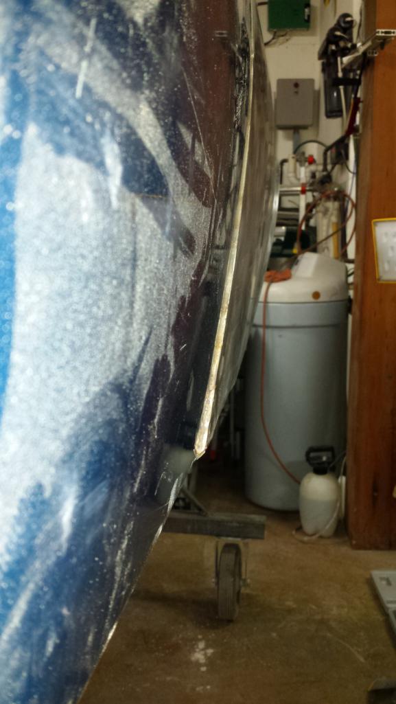 My original idea was to cut a patch out of the old door to replace that corner and address the bottom body line F-up at the same time. I had two problems with that plan. One is that it would add another long butt weld across that panel that is Frankenstein enough as it is, and said butt weld would not be possible with the welder in its current crippled state. The second problem is with yesterday's patch fresh in my head, I knew how hard it would be to bend the weld flange with the curve needed to match the door gap, and would probably require building a hammer form. I decided to try something different and pretended I was a plastic surgeon for the day. The new approach is to just slice the weld flanges of the quarter and lock post open to give the panel a "face lift" to pull it into alignment. 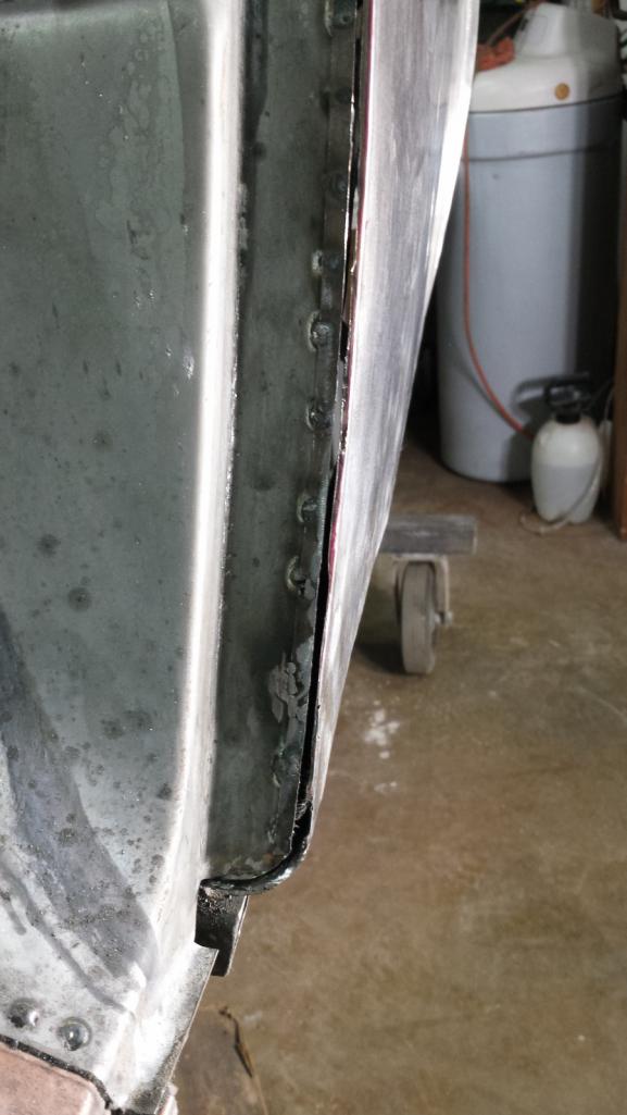 While I had the Dremel out, I also trimmed the weld flange on the RD sail panel piece to match the original width. 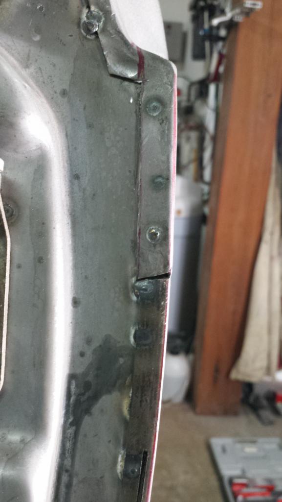 It worked pretty well, my main concern was that the tapered flange width would look goofy, but I don't really think it is noticeable. If it starts bugging me, I have a couple ideas for addressing it. This pic makes the repair look way more ugly than it is. It seems like unless you primer a repair, the camera makes it look a lot better or worse than it actually is. Anyway, the flange looks good and just needs some minor cosmetic cleanup even if you can't tell in this pic. 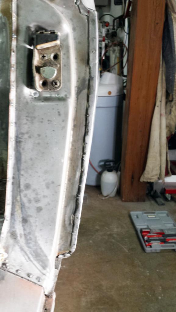 And the new alignment looks good (IMG:style_emoticons/default/cheer.gif) 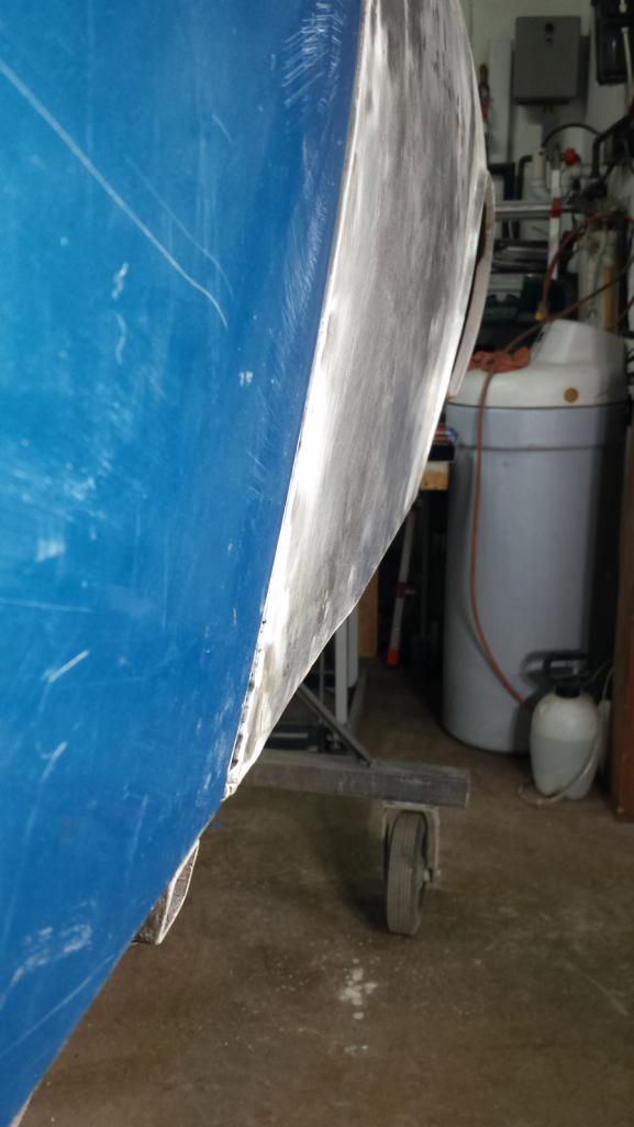 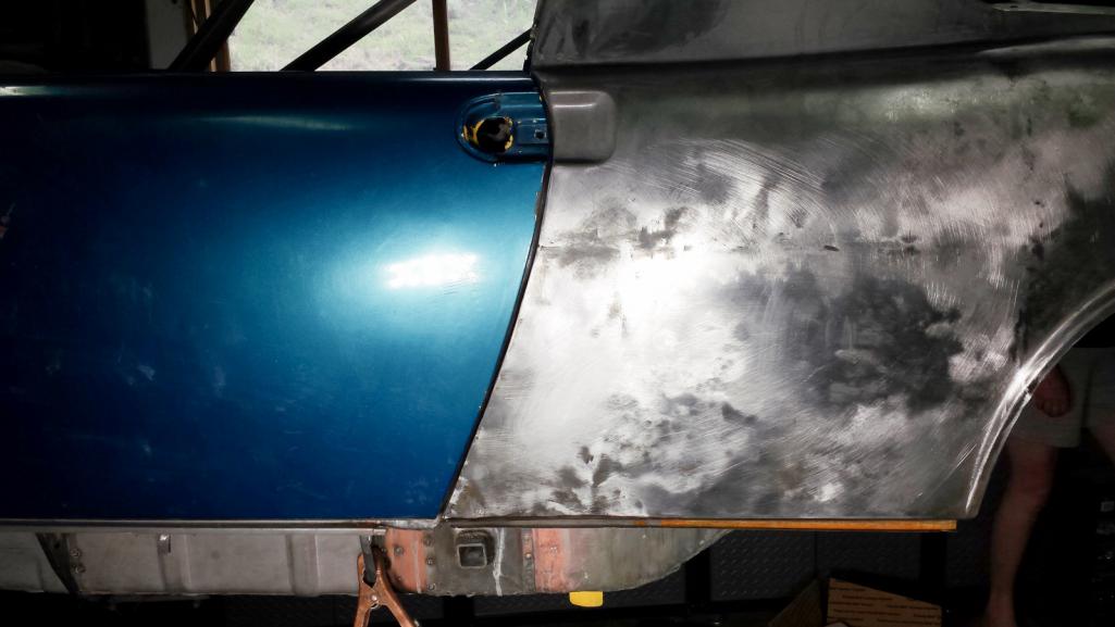 Up next is to use a similar approach to fix the bottom body line that I FUBARed when I patched the rust down there. 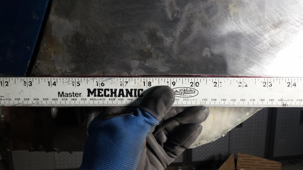 |
|
|
|
| bbrock |
May 28 2018, 08:50 PM
Post
#440
|
|
914 Guru Group: Members Posts: 5,269 Joined: 17-February 17 From: Montana Member No.: 20,845 Region Association: Rocky Mountains |
Well that didn't work
After lunch, I slit open the bend at the bottom of the driver's quarter panel, adjusted the line, and started to weld it back up. 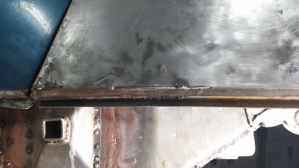 But I had blocked out just how sketchy that part of the panel was to begin with but was quickly reminded as melted lead started dripping down. This is the panel that I had patched rust on the bottom (badly), and then fiddle farted with body solder to smoot and strengthen pitting on the inside from too much road salt. I quickly realized this was not going to be acceptable. So, i spent the rest of the afternoon with shrinking disc, hammer, and dolly to straighten the panel in prep for cutting and patching. The closer I got to that corner, the worse shape the panel was in. Cutting that out will be an improvement in many ways. Still a little more panel beating to do, but its really close. Here the outline of about where I'll cut. 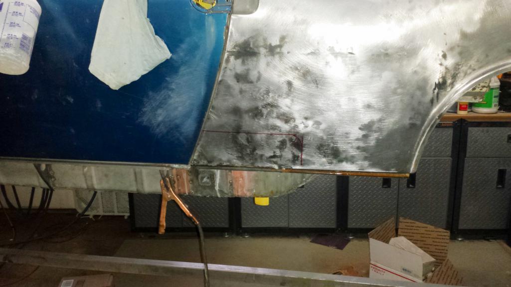 |
|
|
|
|
3 User(s) are reading this topic (3 Guests and 0 Anonymous Users)
0 Members:

|
Lo-Fi Version | Time is now: 19th April 2026 - 04:17 AM |
Invision Power Board
v9.1.4 © 2026 IPS, Inc.