|
|
|
Porsche, and the Porsche crest are registered trademarks of Dr. Ing. h.c. F. Porsche AG.
This site is not affiliated with Porsche in any way. Its only purpose is to provide an online forum for car enthusiasts. All other trademarks are property of their respective owners. |
|
|

  |

| Evan0 |
 May 19 2017, 11:43 PM May 19 2017, 11:43 PM
Post
#21
|
|
Newbie  Group: Members Posts: 44 Joined: 13-February 17 From: Southern California Member No.: 20,837 Region Association: Southern California |
QUOTE(Jeff Bowlsby @ May 19 2017, 06:38 PM)  I generally have concerns about the so-called 'upgraded' panels because many have proven to be problematic discovered only after a short amount of use. This set-up seems to have some positives. The custom relay mounting base seems well done and using the new relays and fuses is commendable. Don't like the cheapo side mount fuseblocks because attaching the chassis harness wiring stresses the wiring- using the flag terminals may address the tight fit but that means that all the original terminals need replacement. PLEASE do not promote using those cheesy insulated terminals. Locate some solid brass double barrel terminals in the appropriate wire gauges as needed without the plastic insulator - because they are not a good long term solution. Thanks for the advice regarding the terminals. I'll find the right flag terminals for final installation. Do you happen to know any of the troubles people have after replacing the panel? I would love to nip those in the bud before I run into them. Addressing the replacement of all the terminals, my harness was mutilated by one of the previous owners, and everything under the dash had to be rewired and re-terminated. I don't have the resources to removed the entire harness and try to replace it with one in better condition. This is complicated by the fact that my car has had a LS1 swap and the electrical wiring is a bit iffy on the documentation. This solution was designed primarily for my needs and definitely need further refinement before anyone else tries to use it. Suggestions and input like this is much appreciated. |
   |

 
|
| JeffBowlsby |
May 20 2017, 07:55 AM
Post
#22
|
|
914 Wiring Harnesses Group: Members Posts: 8,477 Joined: 7-January 03 From: San Ramon CA Member No.: 104 Region Association: None |
The main issues I see are that:
1. The new fuse block mount on another version (not yours) had a metal strap that would short against the power terminal block on the 1970-72 cars. 2. The new stress put on the wiring to wire terminal juncture because of the side terminal locations rather than the original rear mount locations at the fusepanel. The ties organizing the wiring at the fuseblock needs to be loosened up or removed to give enough slack to connect the wires to their new side mount location. Stress on the wires over time will cause the wiring to fail at that stress point. 3. The new fuseblocks do not have the bussed together lugs that the factory fuseblocks do, so makeshift additional terminal busses are needed or the circuitry is altered to accommodate, making the factory wiring schematic useless for troubleshooting. 4. How well made are the new fuse blocks? The ones I have seen are of poor quality relative to the bakelite shell and solid brass fuse terminals of the factory original fuse blocks. People have been replacing the original fuse blocks to use the new style fuses and because some say that they repeatedly kick out the fuses when getting in/out of the car. In 40 years of driving 914s, I have never had any issues with the original fuse blocks. I don't see any benefit to change the fuse block, personally. Attached image(s) 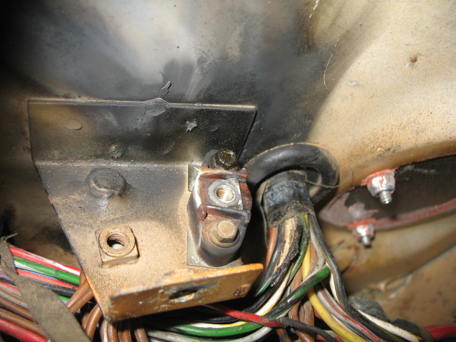 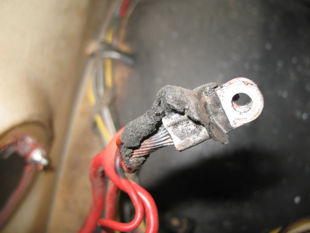 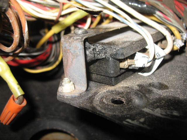 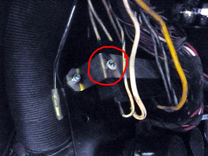 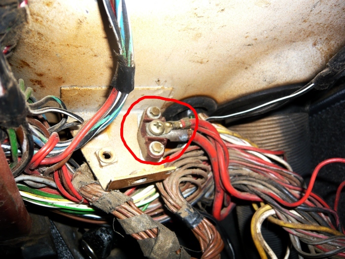
|
|
|
|
| Evan0 |
May 20 2017, 11:41 AM
Post
#23
|
|
Newbie Group: Members Posts: 44 Joined: 13-February 17 From: Southern California Member No.: 20,837 Region Association: Southern California |
QUOTE(Jeff Bowlsby @ May 20 2017, 06:55 AM) The main issues I see are that: 1. The new fuse block mount on another version (not yours) had a metal strap that would short against the power terminal block on the 1970-72 cars. 2. The new stress put on the wiring to wire terminal juncture because of the side terminal locations rather than the original rear mount locations at the fusepanel. The ties organizing the wiring at the fuseblock needs to be loosened up or removed to give enough slack to connect the wires to their new side mount location. Stress on the wires over time will cause the wiring to fail at that stress point. 3. The new fuseblocks do not have the bussed together lugs that the factory fuseblocks do, so makeshift additional terminal busses are needed or the circuitry is altered to accommodate, making the factory wiring schematic useless for troubleshooting. 4. How well made are the new fuse blocks? The ones I have seen are of poor quality relative to the bakelite shell and solid brass fuse terminals of the factory original fuse blocks. People have been replacing the original fuse blocks to use the new style fuses and because some say that they repeatedly kick out the fuses when getting in/out of the car. In 40 years of driving 914s, I have never had any issues with the original fuse blocks. I don't see any benefit to change the fuse block, personally. Thanks for the info. I was wondering if that terminal block for battery power was factory or not. I will try to properly strain relief the wires as they are managed, but your right that it will eventually be an issue due to the tight spacing. The JWest blocks seems to be of good quality and it looks like the terminal blocks are properly bused together for 1-2, 3-4, and 10-12. For the flag connectors, I'm going with the Molex Vibrakrimp series of connectors. They have a insulation grip, which will help offload some stress from the conductor itself. Again, thanks for the insight, you and your site are invaluable resources. |
|
|
|
| mepstein |
Jul 15 2017, 11:28 AM
Post
#24
|
|
914-6 GT in waiting Group: Members Posts: 19,238 Joined: 19-September 09 From: Landenberg, PA/Wilmington, DE Member No.: 10,825 Region Association: MidAtlantic Region |
Any updates. I'm still interested. Thanks, mark
|
 |
|
| Bartlett 914 |
Jul 15 2017, 11:46 AM
Post
#25
|
|
Advanced Member Group: Members Posts: 2,214 Joined: 30-August 05 From: South Elgin IL Member No.: 4,707 Region Association: Upper MidWest |
That is the best conversion I have seen. I hope you don't drop the project. Jeff offered some objective criticism which should help make this the perfect upgrade.
|
|
|
|
| 914Sixer |
Jul 15 2017, 11:55 AM
Post
#26
|
|
914 Guru Group: Members Posts: 8,870 Joined: 17-January 05 From: San Angelo Texas Member No.: 3,457 Region Association: Southwest Region |
I( agree with Jeff about the flag connectors. Can you simply turn the fuse block around and face the spades to the rear? Looks like that would be straight forward move and a solution to the problem.
|
|
|
|
| Evan0 |
Jul 16 2017, 10:49 PM
Post
#27
|
|
Newbie Group: Members Posts: 44 Joined: 13-February 17 From: Southern California Member No.: 20,837 Region Association: Southern California |
I've just gotten my car going again this weekend, and have some changes and improvements that can be made. The board worked, but the current design had some problems during installation, and isn't suitable as a drop in replacement. I have plans for the next iteration that will hopefully be good enough to see the light of day on another 914. Thanks for the patience and constructive input, much appreciated.
|
|
|
|
| NS914 |
Jul 17 2017, 11:17 AM
Post
#28
|
|
Member Group: Members Posts: 198 Joined: 9-June 09 From: Dartmouth, Nova Scotia Member No.: 10,455 Region Association: Canada |
Hey Evan, I am actually into this right now and have been having a heck of a time to get my existing relays should back into the holes in the J West panel...your engineering and initiative would be just the ticket!
I see that after going through a few iterations you continue to develop it. Please put me on your list of future "me too" people. Regards, Grant |
|
|
|
| raynekat |
Jul 19 2017, 08:30 PM
Post
#29
|
|
Advanced Member Group: Members Posts: 2,153 Joined: 30-December 14 From: Coeur d'Alene, Idaho Member No.: 18,263 Region Association: Pacific Northwest |
I have to agree with Jeff Bowlsby on the after market fuse panels.
I'm doing a 914-6 conversion on my 1971 914-4 and I'm using an NOS 1971 chassis wiring harness. I've also got a JWest aftermarket fuse panel. The way this panel works is that the wires on the "inlet" and "outlet" sides of the fuse come in on opposite sides of the panel. Where in the factory panel, the "inlet" and "outlet" wires come in on the same side of the fuse panel. THAT IS A BIG DIFFERENCE WHEN IT COMES TO PLUGGING ALL THESE WIRES IN. I'm seeing that there is a lot of stress on the connectors with the JWest panel and the main harness kind of straddles the panel vs being in behind the panel with the factory setup. So I've decided to ditch the JWest with the new style fuse in lieu of the old fashioned factory style. I can just tell the factory will be a much better setup. Obviously the factory knew what it was doing. |
|
|
|
| raynekat |
Jul 24 2017, 05:35 PM
Post
#30
|
|
Advanced Member Group: Members Posts: 2,153 Joined: 30-December 14 From: Coeur d'Alene, Idaho Member No.: 18,263 Region Association: Pacific Northwest |
This gives you an idea.
On the factory fuse panel, both the incoming and outgoing wires come from approximately the same direction from the main wiring bundle. (A) On the after market panels, the incoming wires must loop around to the backside of the connection block. It seems like this would put a lot of stress on the wire/connector on that side of connection block. These incoming wires are just not long enough coming out of the main wiring bundle to make the journey relatively stress free. (B) One option is to move the main wiring bundle such that it straddles the connection block, but again the direction change that both the incoming and outgoing wires make from the main wiring bundle to the connection block is not idea. In the end, I've decided to stick with my 40 year old factory fuse block design and live with archaic fuse technology. 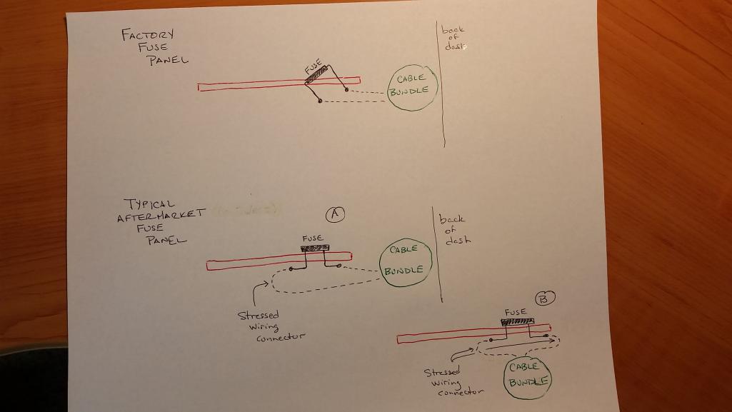 |
|
|
|
| rad23racer |
Jul 24 2017, 11:31 PM
Post
#31
|
|
Newbie Group: Members Posts: 17 Joined: 28-May 17 From: Corona, CA Member No.: 21,137 Region Association: Southern California |
QUOTE(Evan0 @ Jul 16 2017, 09:49 PM) I've just gotten my car going again this weekend, and have some changes and improvements that can be made. The board worked, but the current design had some problems during installation, and isn't suitable as a drop in replacement. I have plans for the next iteration that will hopefully be good enough to see the light of day on another 914. Thanks for the patience and constructive input, much appreciated. I’m in Corona and would like to offer to help with this project. I have CNC and 3D printing available to me as well. In addition, my car is mostly disassembled so things are easy to get to. |
|
|
|
| Evan0 |
Jul 25 2017, 12:38 PM
Post
#32
|
|
Newbie Group: Members Posts: 44 Joined: 13-February 17 From: Southern California Member No.: 20,837 Region Association: Southern California |
Thanks for the input everyone. I have a drastically different approach to the problem than my original design. It should end up being a much better permanent solution as well as lowering the overall cost. I'm also working on replacing the existing fuse block as well with one better suited to the cable organization. I should have a couple units ready to test in a couple weeks if anyone wants to be a guinea pig.
|
|
|
|
| Evan0 |
Aug 14 2017, 10:17 PM
Post
#33
|
|
Newbie Group: Members Posts: 44 Joined: 13-February 17 From: Southern California Member No.: 20,837 Region Association: Southern California |
It's been a few weeks and the first prototype for version 3 are complete. First some background on why version 3 is so drastically different. Between the combination headlight relay, buzzer and other relays, the cost for just the relays was easily over $100. The LED flasher unit from Hella took over 3 months from when I first ordered it to when it arrived. Also the sheer size of the relays and its mount weren't great for placement or installation.
Version 3 consists of a completely custom solution for all the components needed to run a 914. The combination relay, flasher and buzzer are all replicated using discrete logic and solid state relays. The relays are rated for 60 volts and up to 40A peak and 32A continuous. Best part of the this design is that even at a single unit it only costs about $70. (IMG:http://www.914world.com/bbs2/uploads_offsite/i.imgur.com-20837-1502770640.1.jpg) (IMG:http://www.914world.com/bbs2/uploads_offsite/i.imgur.com-20837-1502770641.2.jpg) The relay board assembly is designed fit with its heatsink to the JWest fuse panel. (IMG:http://www.914world.com/bbs2/uploads_offsite/i.imgur.com-20837-1502770641.3.jpg) (IMG:http://www.914world.com/bbs2/uploads_offsite/i.imgur.com-20837-1502770641.4.jpg) (IMG:http://www.914world.com/bbs2/uploads_offsite/i.imgur.com-20837-1502770641.5.jpg) Since I heard a lot of complaints about the JWest panel, I thought I would take a stab at the problem. The terminals emulate the factory panel, with the correct terminals bused together, and it includes the tilt toward the front of the car. It uses standard ATO fuses. This piece would replace the factory fuse block and integrates my new solid state relay solution. A 1.5mm laser etched plate would sit on the front of the fuse block and provide markings and indication. I didn't get that done in time, but it's not critical. (IMG:http://www.914world.com/bbs2/uploads_offsite/i.imgur.com-20837-1502770641.6.jpg) (IMG:http://www.914world.com/bbs2/uploads_offsite/i.imgur.com-20837-1502770641.7.jpg) (IMG:http://www.914world.com/bbs2/uploads_offsite/i.imgur.com-20837-1502770641.8.jpg) (IMG:http://www.914world.com/bbs2/uploads_offsite/i.imgur.com-20837-1502770641.9.jpg) I hope this version will be the one to makes it to production. Feedback, improvements, and comments are appreciated. The first couple units are going to be stress tested over the next couple of weeks to validate the design. |
|
|
|
| euro911 |
Aug 14 2017, 11:12 PM
Post
#34
|
|
Retired & living the dream. God help me if I wake up! Group: Members Posts: 8,845 Joined: 2-December 06 From: So.Cal. & No.AZ (USA) Member No.: 7,300 Region Association: Southern California |
Very nice, Evan. With the solid-state relays you've employed, will this cure the load issue when running LED turn signals?
Also, this unit is all that's needed to supplant the J-West or Engman fuse blocks and relay unit(s)? If you're still looking for guinea pigs ... I'm your huckleberry (IMG:style_emoticons/default/laugh.gif) |
|
|
|
| Evan0 |
Aug 14 2017, 11:33 PM
Post
#35
|
|
Newbie Group: Members Posts: 44 Joined: 13-February 17 From: Southern California Member No.: 20,837 Region Association: Southern California |
QUOTE(euro911 @ Aug 14 2017, 10:12 PM) Very nice, Evan. With the solid-state relays you've employed, will this cure the load issue when running LED turn signals? Also, this unit is all that's needed to supplant the J-West or Engman fuse blocks and relay unit(s)? If you're still looking for guinea pigs ... I'm your huckleberry (IMG:style_emoticons/default/laugh.gif) It doesn't have the load issue with LEDs, but it does require that the turn signal indicator lamp be replaced with a LED bulb as well. It's a annoying limitation of the design. The integrated fuse and relay panel would be all you needed. |
|
|
|
| McMark |
Aug 15 2017, 10:35 AM
Post
#36
|
|
914 Freak! Group: Retired Admin Posts: 20,179 Joined: 13-March 03 From: Grand Rapids, MI Member No.: 419 Region Association: None |
That's pretty freakin' awesome.
|
|
|
|
| euro911 |
Aug 15 2017, 12:45 PM
Post
#37
|
|
Retired & living the dream. God help me if I wake up! Group: Members Posts: 8,845 Joined: 2-December 06 From: So.Cal. & No.AZ (USA) Member No.: 7,300 Region Association: Southern California |
With Jerry's LED lights, Timothy's LED gauges and Evan's relay panel, there's some real nifty stuff available these days (IMG:style_emoticons/default/biggrin.gif)
|
|
|
|
| McMark |
Aug 15 2017, 01:44 PM
Post
#38
|
|
914 Freak! Group: Retired Admin Posts: 20,179 Joined: 13-March 03 From: Grand Rapids, MI Member No.: 419 Region Association: None |
Thought of something...
While I love the wire color printed on the board, I thought some of the wire colors changed on different years. It may be better to simply label each connection with the original relay pin number (30, 85, 86, 87, 87a). If I were troubleshooting a car with that board installed and I wouldn't want to have to pull out and analyze the wiring diagram to translate wire colors to pin number and function. On the fuse board, it would be prudent to add either a couple extra constant power connections and a couple switched power connections, OR add a couple extra fuses for add-ons. |
|
|
|
| GregAmy |
Aug 15 2017, 02:32 PM
Post
#39
|
|
Advanced Member Group: Members Posts: 2,267 Joined: 22-February 13 From: Middletown CT Member No.: 15,565 Region Association: North East States |
|
|
|
|
| mepstein |
Aug 15 2017, 02:34 PM
Post
#40
|
|
914-6 GT in waiting Group: Members Posts: 19,238 Joined: 19-September 09 From: Landenberg, PA/Wilmington, DE Member No.: 10,825 Region Association: MidAtlantic Region |
QUOTE(McMark @ Aug 15 2017, 03:44 PM) Thought of something... On the fuse board, it would be prudent to add either a couple extra constant power connections and a couple switched power connections, OR add a couple extra fuses for add-ons. (IMG:style_emoticons/default/agree.gif) it would make engine conversions a lot easier to have the extra connections. Love what you are doing. |
|
|
|
|
1 User(s) are reading this topic (1 Guests and 0 Anonymous Users)
0 Members:

|
Lo-Fi Version | Time is now: 25th April 2024 - 09:30 AM |
Invision Power Board
v9.1.4 © 2024 IPS, Inc.