|
|
|
Porsche, and the Porsche crest are registered trademarks of Dr. Ing. h.c. F. Porsche AG.
This site is not affiliated with Porsche in any way. Its only purpose is to provide an online forum for car enthusiasts. All other trademarks are property of their respective owners. |
|
|

  |

| scotty914 |
 Jun 26 2005, 01:21 PM Jun 26 2005, 01:21 PM
Post
#101
|
|
suby torque rules  Group: Members Posts: 1,528 Joined: 20-July 03 From: maryland, the land of 25 year Member No.: 924 |
the purge valve is on the engine harnes. the way it worked was the pressure sensor work thru a swotching solinoid that read intake pressure and atmosphereic pressure which were on the body harness. there where two valves on the engine one was the egr control the other is a purge valve for the tank fumes
at least this is how it si on pre 00 miles |
   |

 
|
| TonyAKAVW |
Jul 28 2005, 02:16 AM
Post
#102
|
|
That's my ride. Group: Members Posts: 2,151 Joined: 17-January 03 From: Redondo Beach, CA Member No.: 166 Region Association: None |
Slowly but surely I've been making progress. The metal work on the car has slowed down a bit but in its place, the electrical work has progressed.
I finished the replacement for my relay board. It has a 5-position fuse block and three relays. One for system power, and two for each of the two radiator fans. There is room for a 4th relay for a heater blower, but that is an upgrade I will make when the time comes. The new relay board is built inside of a weatherproof plastic housing with a hinged transparent lid. The box will mount to the side of the engine bay where the old relay board would sit. The box lid will open down for easy access to replace fuses or relays. I still need to drill a hole in the bottom for the wiring to go through and the large gray plastic Anderson Power conenctor will possibly be mounted on the bottom of the box. This connects to the alternator cable. |
|
|
|
| TonyAKAVW |
Jul 28 2005, 02:17 AM
Post
#103
|
|
That's my ride. Group: Members Posts: 2,151 Joined: 17-January 03 From: Redondo Beach, CA Member No.: 166 Region Association: None |
oops. forgot the picture...
Attached image(s) 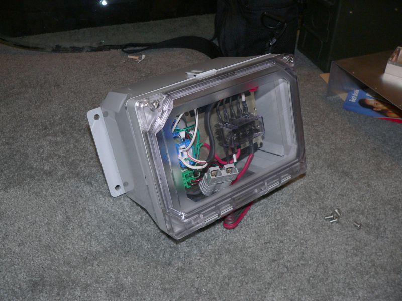
|
|
|
|
| TonyAKAVW |
Jul 28 2005, 02:17 AM
Post
#104
|
|
That's my ride. Group: Members Posts: 2,151 Joined: 17-January 03 From: Redondo Beach, CA Member No.: 166 Region Association: None |
The guts.
Attached image(s) 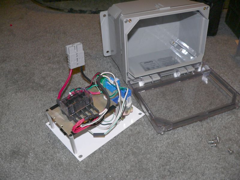
|
|
|
|
| TonyAKAVW |
Jul 28 2005, 02:22 AM
Post
#105
|
|
That's my ride. Group: Members Posts: 2,151 Joined: 17-January 03 From: Redondo Beach, CA Member No.: 166 Region Association: None |
The next piece I have been working on isn't quite finished yet, but is close enough for some progress to be reported.
This box will sit on top of the ECU and simulate various sensors. The resistors are not in place, but the PCB is wired up and mounted to the housing. The PCB is unusual in color - white. Thats because the PCB is some scrap (expensive) ceramic/PTFE material that I had laying around. No particualr reason that its any better or worse for this application. The housing is another piece of scrap. It once housed some kind of predistortion circuit for a microwave amplifier and probably cost more than what many of us payed for our 914s. Its a lovely chunk of hogged out and chem-filmed aluminum. The plastic lid I made myself. There's a red LED indicator inside to show that the power supply for the sensors is active. Attached image(s) 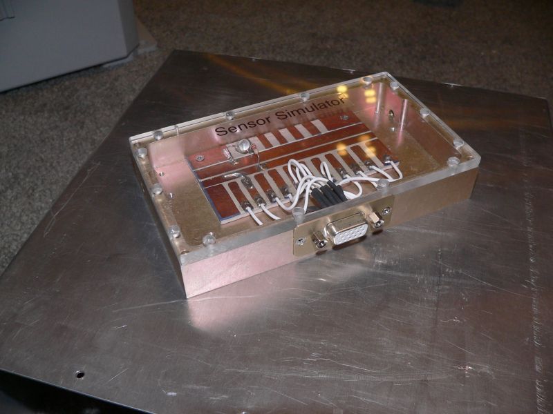
|
|
|
|
| turbo914v8 |
Jul 28 2005, 05:09 AM
Post
#106
|
|
Member Group: Members Posts: 373 Joined: 26-July 03 From: Canada Member No.: 952 |
Just curious, what sensors did you have to simulate. We are all enjoying your progress reports, Great project.
|
|
|
|
| mongrel-gs |
Jul 28 2005, 05:58 AM
Post
#107
|
|
Member Group: Members Posts: 55 Joined: 29-November 04 From: Baltimore, MD Member No.: 3,194 |
That sure is a nice system for the relays and such!
|
|
|
|
| CptTripps |
Jul 28 2005, 06:08 AM
Post
#108
|
|
:: Punch and Pie :: Group: Members Posts: 3,586 Joined: 26-December 04 From: Tuscaloosa, AL and Akron, OH Member No.: 3,342 Region Association: Upper MidWest |
How have I been missing this thread?
Awesome work...I'm taking notes! |
|
|
|
| TonyAKAVW |
Jul 28 2005, 10:21 AM
Post
#109
|
|
That's my ride. Group: Members Posts: 2,151 Joined: 17-January 03 From: Redondo Beach, CA Member No.: 166 Region Association: None |
Okay, so I will be simulating the following sensors..
Fuel level sender (0.12 to 4.95 volts) Fuel Temp sender (2.5 to 3.8 volts) Fuel Tank Pressure sender (2.3 to 2.7 volts) Rear O2 sensor signal (0 - 0.9 volts) Neutral position sensor (+12 in neutral, 0 when in gear) Rear O2 heater sensor signal (0-1.0 volts) Power Steering oil pressure sender (open/close) There may be one more, I'm still finalizing the wiring... Most of these wil use small 10-turn potentiometers to set the desired signal voltage, but I may end up using real metal-film resistors in the end, as they are a bit more reliable. -Tony |
|
|
|
| phantom914 |
Jul 28 2005, 11:18 AM
Post
#110
|
||
|
non-914-owner non-club member Group: Benefactors Posts: 1,013 Joined: 24-February 04 From: Covina,CA(North ofWest Covina) Member No.: 1,708 |
Yes, please don't use the fake metal-film resistors, even though the low price may be tempting. Andrew |
||
|
|
|
||
| airsix |
Jul 28 2005, 12:54 PM
Post
#111
|
||
|
I have bees in my epiglotis Group: Members Posts: 2,196 Joined: 7-February 03 From: Kennewick Man (E. WA State) Member No.: 266 |
Cool! With just a few minor tweeks you can make it look like the 'flux capacitor'. (Not making fun. I think it's great.) -Ben M. (IMG:http://www.bfcoulombe.com/flux20.jpg) |
||
|
|
|
||
| TonyAKAVW |
Jul 28 2005, 02:24 PM
Post
#112
|
|
That's my ride. Group: Members Posts: 2,151 Joined: 17-January 03 From: Redondo Beach, CA Member No.: 166 Region Association: None |
You know, Bondo mentioned that to me, that the box looks like a flux capacitor. Maybe I should put a label on it that says "Warning! Do Not Exceed 88 mph"
Making a gullwing 914 would be an interesting challenge. (IMG:http://www.914world.com/bbs2/html/emoticons/idea.gif) -Tony |
|
|
|
| scotty914 |
Jul 28 2005, 02:41 PM
Post
#113
|
|
suby torque rules Group: Members Posts: 1,528 Joined: 20-July 03 From: maryland, the land of 25 year Member No.: 924 |
the power steering pressure is not nessesary to fake it only closes when it loses pressure. but what you could do to make use of it is to connect it to a thermostat set at about 215 degrees, that way you get the extra signal ( cel ) if your temp goes high.
i also think you are going over board on the resisitor thing just intragrate them in to the harness |
|
|
|
| TonyAKAVW |
Jul 28 2005, 03:20 PM
Post
#114
|
||
|
That's my ride. Group: Members Posts: 2,151 Joined: 17-January 03 From: Redondo Beach, CA Member No.: 166 Region Association: None |
I am absolutely going overboard (IMG:http://www.914world.com/bbs2/html/emoticons/smile.gif) But then I wouldn't do it any other way. -Tony |
||
|
|
|
||
| Kostamojen |
Jul 30 2005, 04:56 PM
Post
#115
|
|
Newbie Group: Members Posts: 37 Joined: 30-July 05 From: Roseville, CA Member No.: 4,504 |
Wow, nice work!
I'm a long time NASIOC member, and have a '95 Impreza with an MY2000 EJ25 conversion so this is a great read (Ive been looking at 914 stuff lately cause of the posts recently on NASIOC about the Renegage conversion, and the fact there is a 914 thats been forsale for like a year around the corner from my house (IMG:http://www.914world.com/bbs2/html/emoticons/tongue.gif) ) That sensor simulator is a great piece, if you manage to get it to simulate both 02 sensors you can have alot of fun with the exhaust design (IMG:http://www.914world.com/bbs2/html/emoticons/idea.gif) I was wondering if anyone has thought about using a cowel induction style intake with the N/A scoob motors on the 914's... There was a I-club member awhile back who had one using a PRM style intake filter, might be a neat idea for the swap. As far as engine mounts go, I was curious whether you would be using the Subaru mounts or just bolting directly to your fabricated mount... For everyone else looking into Subaru swaps, there are ALOT of very new very cheap motors (usually JDM imports) showing up now, vendors usually are selling them on the forums. Keep an eye out here if you are shopping for one: http://forums.nasioc.com/forums/forumdisplay.php?f=112 (Gruppe-S still has a brand new EZ30-R motor for ~$1500, the 250hp/215ft-lbs H6 from the new legacies, which gives me wicked ideas for a 914 conversion since it still uses the same motor mounts and such as the EJ motors... But I still think a verison 8 STI motor with its 8k redline combined with a high strung turbo would be a great motor for 914 but I dont think the tranny will take it (IMG:http://www.914world.com/bbs2/html/emoticons/icon8.gif) ) |
|
|
|
| TonyAKAVW |
Jul 31 2005, 10:40 AM
Post
#116
|
|
That's my ride. Group: Members Posts: 2,151 Joined: 17-January 03 From: Redondo Beach, CA Member No.: 166 Region Association: None |
Welcome to the 914club!
Regardnig the sensor simulator, I won't be simulating the front O2 sensor. That is used by the ECU to run the enigne, whereas the second sensor is there just to verify the cat is working. Since I'm not going to be running a cat, I have to simulate the second sensor. Don't really know what a Cowell induction is... For the engine mount, I will be using the Subaru rubber engine mounts, which will be bolted to a roughly U-shaped bar which cradles the engine. That EZ30 engine sounds like a great engine for a 914. I wonder if you could still fit it in the engine bay with the radiator back there. If so, that would be THE killer setup. -Tony |
|
|
|
| redshift |
Jul 31 2005, 01:37 PM
Post
#117
|
|
Bless the Hell out of you! Group: Members Posts: 10,926 Joined: 29-June 03 Member No.: 869 |
Tony... Tone... Toni... YOU ARE A NUT!
How cool is that!? (IMG:http://www.914world.com/bbs2/html/emoticons/ohmy.gif) I swear, we don't even need cars to start with, we just need aluminum Chinese made copies, and the upper 2% of the club's brain trust to come up with awesome hardware to fill the holes with. (IMG:http://www.914world.com/bbs2/html/emoticons/smile.gif) M |
|
|
|
| Dr. Roger |
Jul 31 2005, 02:52 PM
Post
#118
|
|
A bat out of hell. Group: Members Posts: 3,944 Joined: 31-January 05 From: Hercules, California Member No.: 3,533 Region Association: Northern California |
(IMG:http://www.914world.com/bbs2/html/emoticons/hijacked.gif) Hmmm, first time i've used that emoticon.. fun.
Miles, I just followed your sig link Which lead me to another link. Website dedicated to busting pervs. Sick old pervs flirt with 14 YO girls on AOL chat, offer to pay them a visit or they visit the guys, and then nail them with the help from the cops. How cool is that? "Want some candy?"... (IMG:http://www.914world.com/bbs2/html/emoticons/blink.gif) |
|
|
|
| Kostamojen |
Aug 4 2005, 05:28 PM
Post
#119
|
||
|
Newbie Group: Members Posts: 37 Joined: 30-July 05 From: Roseville, CA Member No.: 4,504 |
The cowel induction intake I mentioned was a little side project from a NASIOC member from a long time ago: http://forums.nasioc.com/forums/showthread...ighlight=intake Upon looking more at the 914 engine bay, it might not be a super great idea, but I'm curious now about what kind of intake designs people are doing with the scoobie engines... As for the engine mounts, you might want to look into at least upgrading to STI engine mounts: http://www.rallispec.com/sub_drivemt.htm Its not super expensive, but it may eliminate some concerns you have about engine movement. I mention this cause I saw that the other engine mount pic posted by Turbo914v8 and it looks like those might be the Group N mounts ($$$, also on that Rallispec page) I dont think the radiator will fit in the engine bay with the EZ30, it is a tad bit longer than an EJ motor (But not THAT much longer, it fits in Impreza engine bays just fine) |
||
|
|
|
||
| Burg |
Aug 7 2005, 04:26 AM
Post
#120
|
|
Newbie Group: Members Posts: 1 Joined: 7-August 05 From: Munich Member No.: 4,549 |
Hello, just a simple question from a newbie. If you do a suby conversion and you want to go turbo, which one would you prefer:
1. 2.0 WRX single turbo 2. 2.0 WRX STI twin turbo 3. 2.5 WRX STI single turbo What do you think? Burg |
|
|
|
|
1 User(s) are reading this topic (1 Guests and 0 Anonymous Users)
0 Members:

|
Lo-Fi Version | Time is now: 24th June 2026 - 04:40 PM |
Invision Power Board
v9.1.4 © 2026 IPS, Inc.