|
|
|
Porsche, and the Porsche crest are registered trademarks of Dr. Ing. h.c. F. Porsche AG.
This site is not affiliated with Porsche in any way. Its only purpose is to provide an online forum for car enthusiasts. All other trademarks are property of their respective owners. |
|
|

  |

| TonyAKAVW |
 May 9 2006, 11:02 AM May 9 2006, 11:02 AM
Post
#281
|
|
That's my ride.  Group: Members Posts: 2,151 Joined: 17-January 03 From: Redondo Beach, CA Member No.: 166 Region Association: None |
Thanks for all the comments.
Fiid: Yes, that's the beginning of a 901 cable shifter cconversion. I've decided that I need to build the part that goes onto the transmission much stronger, so that prototype will just be for getting the dimensions right. I need to borrow some time on a milling machine to make a suitably strong cable adapter. jsteele22: The engine bay SUCKS to prep for paint. Its a maze of tight corners, bad painting by the factory (I sanded down several runs, there were lots of little holes in the final paint too) and lots of seam sealant that cracks and traps water. Painting it should be similarly difficult, so I need to get some practice in before I do the job. I've already addressed much earlier on in this thread why I've chosen not to use a Renegade setup. Kind of like why people climb mountains. "Because its there." -Tony |
   |

 
|
| TonyAKAVW |
May 17 2006, 10:58 AM
Post
#282
|
|
That's my ride. Group: Members Posts: 2,151 Joined: 17-January 03 From: Redondo Beach, CA Member No.: 166 Region Association: None |
This progress was posted at Pelican parts during the Great 914Club Hacker Blackout. I'm posting them here to keep the thread as a record of the work.
Attached image(s) 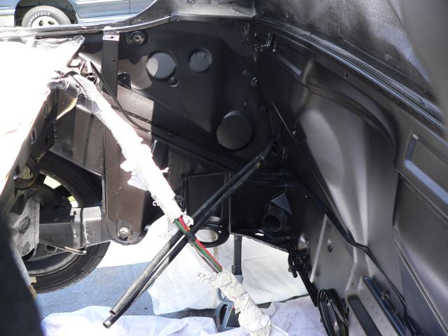 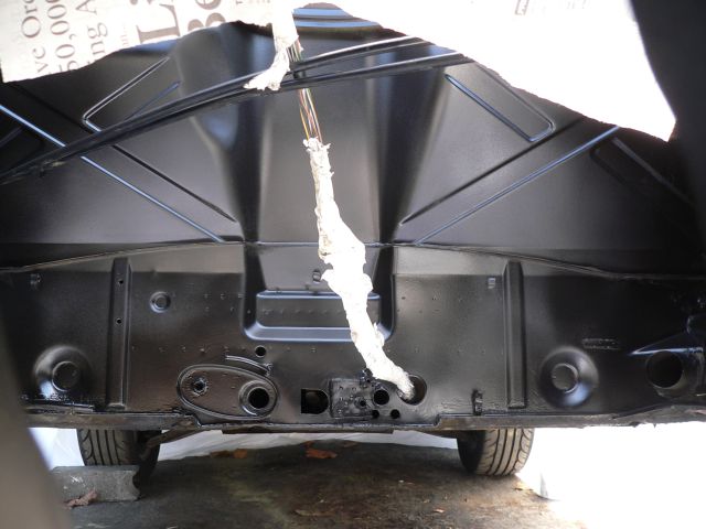 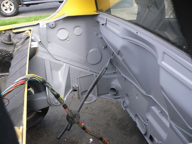 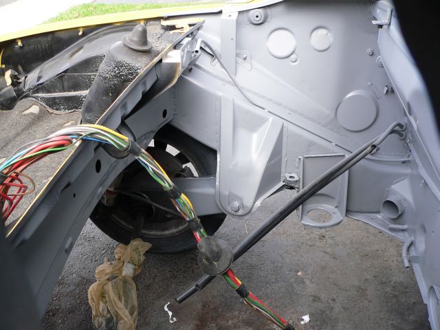
|
|
|
|
| TonyAKAVW |
May 29 2006, 01:56 AM
Post
#283
|
|
That's my ride. Group: Members Posts: 2,151 Joined: 17-January 03 From: Redondo Beach, CA Member No.: 166 Region Association: None |
Stuff is now starting to get put into the engine bay. So far I haev put the battery back in, installed the new junction box, put back the brake proportioning valve, and brand new rigid rear brake lines. Also reconnected the parking brake tubes. The radiator frame is the next item to install. I am now thinking that I want to put some kind of rubber sheet or some sort of protection against the firewall to prevent it from being damaged by a continual spray of water laden hot air.
-Tony Attached image(s) 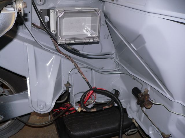 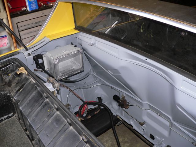 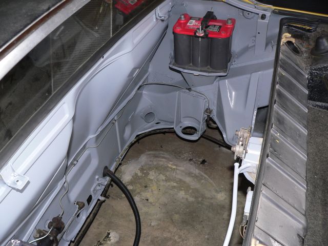
|
|
|
|
| redshift |
May 29 2006, 04:10 AM
Post
#284
|
|
Bless the Hell out of you! Group: Members Posts: 10,926 Joined: 29-June 03 Member No.: 869 |
WOW!I am going to have the most worthless teener in all creation! FANTASTIC LOOKING WORK TONY!
(IMG:style_emoticons/default/smilie_pokal.gif) M! |
|
|
|
| John G |
May 29 2006, 11:18 AM
Post
#285
|
|
Member Group: Members Posts: 97 Joined: 5-May 06 From: Alabama Member No.: 5,988 |
Tony,
When I was looking at Jake Raby's car, he mentioned that he sprayed the entire engine compartment with Line-X; one of those pickup bedliner products. I'm not sure how heat resistant that stuff is, but that might be a solution for your firewall. Your engine bay looks PRISTINE. Great work! John |
|
|
|
| jimkelly |
May 29 2006, 06:02 PM
Post
#286
|
|
Delaware USA Group: Members Posts: 4,969 Joined: 5-August 04 From: Delaware, USA Member No.: 2,460 Region Association: MidAtlantic Region |
|
|
|
|
| TonyAKAVW |
May 29 2006, 10:14 PM
Post
#287
|
|
That's my ride. Group: Members Posts: 2,151 Joined: 17-January 03 From: Redondo Beach, CA Member No.: 166 Region Association: None |
More progress! Today I installed the radiator frame, made a shroud to cover the cable outlets, and put the radiator in.
Attached image(s) 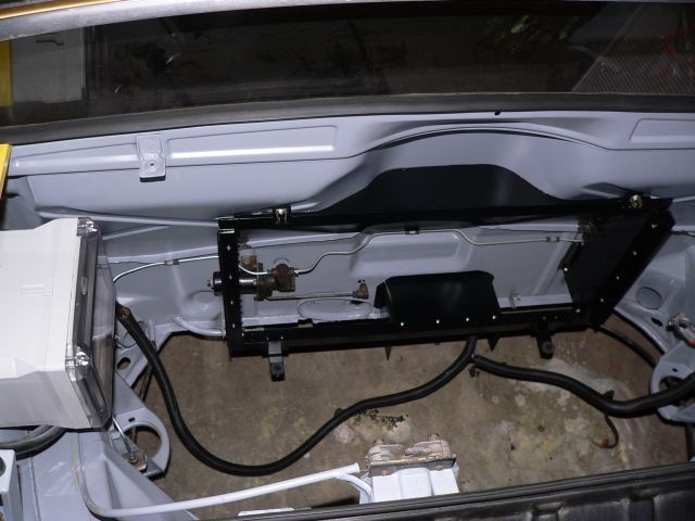 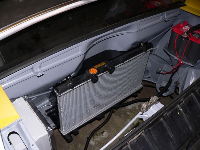 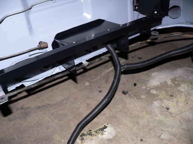 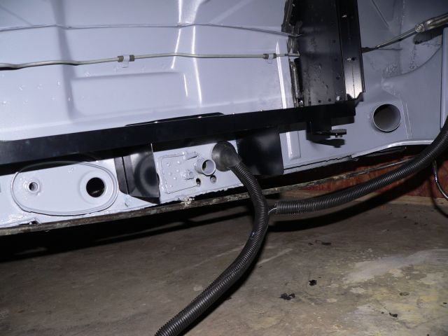
|
|
|
|
| TonyAKAVW |
May 29 2006, 10:15 PM
Post
#288
|
|
That's my ride. Group: Members Posts: 2,151 Joined: 17-January 03 From: Redondo Beach, CA Member No.: 166 Region Association: None |
,,
Attached image(s) 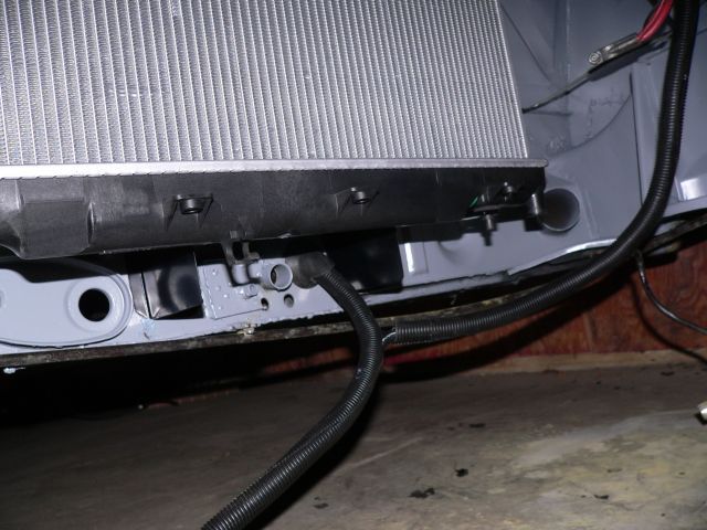 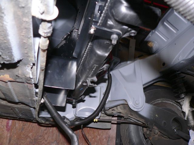
|
|
|
|
| KaptKaos |
May 29 2006, 10:24 PM
Post
#289
|
|
Family Group: Members Posts: 4,009 Joined: 23-April 03 From: Near Wausau Member No.: 607 Region Association: Upper MidWest |
Looks awesome Tony!
Whats the schedule for the rest? |
|
|
|
| TonyAKAVW |
May 29 2006, 10:34 PM
Post
#290
|
|
That's my ride. Group: Members Posts: 2,151 Joined: 17-January 03 From: Redondo Beach, CA Member No.: 166 Region Association: None |
Well, I've got a number of things in the works right now. The one thing that will definitely take some time is that I need to order a new flywheel from KEP and apparently there is a 5 week lead time on that part. In the meantime though I need to finish wiring, install the ECU, and get some serious work done on my cable shifter. So at least two months until its ready to roll.
-Tony |
|
|
|
| Aaron Cox |
May 29 2006, 10:36 PM
Post
#291
|
|
Professional Tinkerer Group: Retired Admin Posts: 24,548 Joined: 1-February 03 From: Corona, CA Member No.: 219 Region Association: Southern California |
looks so foreign... with a radiator in the engine bay...
this aint no front engine "i get air flow" car.... looks sick. hope your cooling works (IMG:style_emoticons/default/smile.gif) |
|
|
|
| KaptKaos |
May 29 2006, 10:41 PM
Post
#292
|
|
Family Group: Members Posts: 4,009 Joined: 23-April 03 From: Near Wausau Member No.: 607 Region Association: Upper MidWest |
QUOTE(TonyAKAVW @ May 29 2006, 09:34 PM)  Well, I've got a number of things in the works right now. The one thing that will definitely take some time is that I need to order a new flywheel from KEP and apparently there is a 5 week lead time on that part. In the meantime though I need to finish wiring, install the ECU, and get some serious work done on my cable shifter. So at least two months until its ready to roll. -Tony Bummer on that lead time. Just let me know when you need a hand. |
|
|
|
| redshift |
May 30 2006, 06:35 AM
Post
#293
|
|
Bless the Hell out of you! Group: Members Posts: 10,926 Joined: 29-June 03 Member No.: 869 |
Damn TONY! Your work is METICULOUS! WHAT A BLOWOUT! UNREAL!
I am.. I just can't believe it! M |
|
|
|
| jimkelly |
Jun 1 2006, 04:18 PM
Post
#294
|
|
Delaware USA Group: Members Posts: 4,969 Joined: 5-August 04 From: Delaware, USA Member No.: 2,460 Region Association: MidAtlantic Region |
Looks like the lower bracket/shifter box blocks about 33% of the potential inbound air flow? Any thoughts of cutting in some holes at the top? Ditto on the beautiful job and progress : )
|
|
|
|
| TonyAKAVW |
Jun 1 2006, 04:59 PM
Post
#295
|
|
That's my ride. Group: Members Posts: 2,151 Joined: 17-January 03 From: Redondo Beach, CA Member No.: 166 Region Association: None |
The aperature blockage is actually the exhaust aperature. This cooling system will operate from the top down. That is, I will have a small spoiler just past the trailing edge of the roof line which upon positioning into the airstream will divert lots of air down into the engine bay. Instead of the usual engine lid grill I am going to use a series of vanes to aid in directing the air down. These vanes will extend up into the area that is normally solid. In the end it will be a super-GT-style engine bay lid.
The spoiler will attach to the car using the bolt holes for a ski rack. I still haven't quite figured out the details of it, but at some speed it will rise up into the air stream and push air into the engine bay. As a further aide, I'm going to enclose the bottom of the car with a huge fiberglass sheet that will have an opening for the radiator exhaust, and a pair of venturi tunnels. By transitioning from a zone of high pressure (at the radiator exhaust) to a zone of low pressure (right behind the car) by means of an expanding tunnel, I ought to get a pretty decent pressure decrease under the car (in theory). Ideally this will benefit cooling by sucking air through the radiator, and at high speed may help to decrease lift. -Tony Attached image(s) 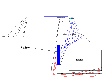
|
|
|
|
| Allan |
Jun 1 2006, 05:28 PM
Post
#296
|
|
Teenerless Weenie Group: Members Posts: 8,373 Joined: 5-July 04 From: Western Mesopotamia Member No.: 2,304 Region Association: Southern California |
QUOTE(Aaron Cox @ May 29 2006, 09:36 PM) looks so foreign... with a radiator in the engine bay... (IMG:style_emoticons/default/agree.gif) Can't wait to see it on the PV peninsula. |
|
|
|
| Dr Evil |
Jun 1 2006, 06:32 PM
Post
#297
|
|
Send me your transmission! Group: Members Posts: 23,041 Joined: 21-November 03 From: Loveland, OH 45140 Member No.: 1,372 Region Association: MidAtlantic Region |
Air flow proof (IMG:style_emoticons/default/biggrin.gif)
Attached image(s) 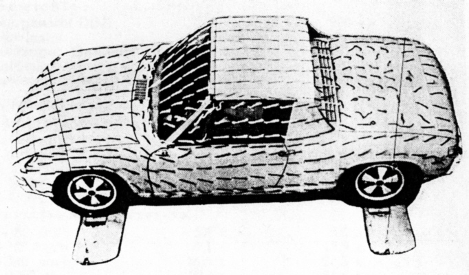
|
|
|
|
| Jes |
Jun 4 2006, 02:41 AM
Post
#298
|
|
Newbie Group: Members Posts: 26 Joined: 16-November 05 From: Redondo Beach, CA Member No.: 5,132 |
Attached image(s) 
|
|
|
|
| banksyinoz |
Jun 4 2006, 04:01 AM
Post
#299
|
|
finally getting back into it Group: Members Posts: 223 Joined: 17-June 05 From: queensland, aus Member No.: 4,293 Region Association: Australia and New Zealand |
great lookin work tony hope to see video of the end result as i wll never see the car in the flesh
(IMG:style_emoticons/default/clap56.gif) (IMG:style_emoticons/default/clap56.gif) (IMG:style_emoticons/default/clap56.gif) (IMG:style_emoticons/default/clap56.gif) |
|
|
|
| TonyAKAVW |
Jun 11 2006, 11:05 PM
Post
#300
|
|
That's my ride. Group: Members Posts: 2,151 Joined: 17-January 03 From: Redondo Beach, CA Member No.: 166 Region Association: None |
Got a few things done over the last week or two.
* Put carpet on the inside of the firewall. Doesn't look concourse, but its decent enough for me. * Took the Subaru ECU out of that silly wooden box from several pages back. Not sure exactly what I'll do in the end, but for now I am using a plate of aluminum with rubber vibration dampeners mounted to the center tunnel. Still working on this... * Ordered and took delivery of stainless steel lines for fuel. I bought 6 foot lengths of stainless tubing from Mcmaster Carr. Less than $20 for the two pieces and they come delivered in a cool packaging tube, useful for who knows. * Began installation of said fuel lines. Instead of Clay's method of using a die to thread the tubing, I made a beading tool. Basically I took a vice grip and ground down the tip as show in pictures below. it works pretty well, though I might make it differently if I did it again. The bead is not as high as I would like but I think its sufficient. * Made and installed a mount for the fuel pump and mounted the pump. I took a sheet of 1/8" aluminum plate and cut it to fit the engine mount. Used a couple Mcmaster Carr rubber isolation mounts and powder coated the whole thing. The gray doesn't match particularly well to the engine bay, but whatever. So thats about it. I'm guessing by the end of this week i'll have the gas tank back in, connected up to the new fuel lines, and have the lines held in place with some kind of bracket, etc. Note: cheapo tubing benders have a hard time with this tubing. Mine got bent out of shape bending the 3/8" stuff. -Tony Attached image(s) 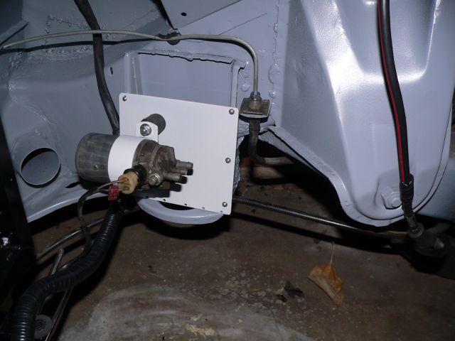 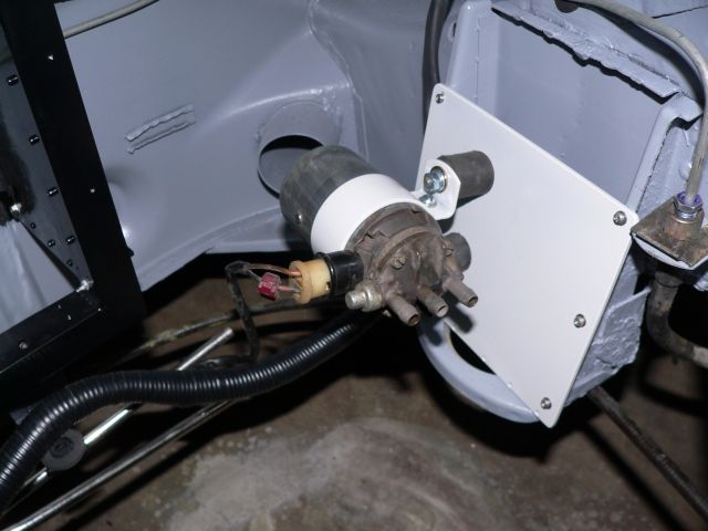 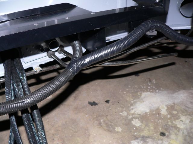 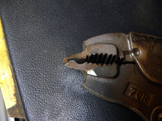
|
|
|
|
|
2 User(s) are reading this topic (2 Guests and 0 Anonymous Users)
0 Members:

|
Lo-Fi Version | Time is now: 25th November 2025 - 12:10 PM |
Invision Power Board
v9.1.4 © 2025 IPS, Inc.