|
|
|
Porsche, and the Porsche crest are registered trademarks of Dr. Ing. h.c. F. Porsche AG.
This site is not affiliated with Porsche in any way. Its only purpose is to provide an online forum for car enthusiasts. All other trademarks are property of their respective owners. |
|
|

  |

| nditiz1 |
 Sep 3 2017, 06:25 AM Sep 3 2017, 06:25 AM
Post
#1
|
|
Senior Member  Group: Members Posts: 1,188 Joined: 26-May 15 From: Mount Airy, Maryland Member No.: 18,763 Region Association: MidAtlantic Region |
I am trying to tie up some loose ends regarding the relays in the fuse panel. Let me first ask the question, is this the right functionality/description of each?
1st round relay ( closest to driver door) - buzzer, controls the door buzzer when the key is in and the door is open 2nd round relay - aux lights, Controls the fog lights 3rd round relay - fresh air box, controls wipers, fresh air box, horn? 4th square relay - headlight dimmer, controls high beam low beam? 5th round metal relay (behind square relay) - don't know I had been having an issue with my fresh air and wipers and believe that the relay was the cause. It would work intermittently and even keep the fresh air on after the car was turned off. I swapped in a used one I got off ebay, but it didn't seem to fix it. I then swapped it with one of the other 2. It worked and I was able to turn on the wipers and fresh air. When I turned off the car the fresh air would stop. I was not able to hit the horn button when the car was not on. Question 2 does your horn work if the car is off? I swapped in the supposed faulty relay into the fog light position and it worked. Question 3 can part of the relay fail to function, but in other spots it work? Question 4 how can you test a relay to ensure it works? Question 5 does anyone know which accessories work when the car is off besides the running lights and hazards? Thanks! |
   |

 
|
| 76-914 |
Sep 3 2017, 08:54 AM
Post
#2
|
|
Repeat Offender & Resident Subaru Antagonist Group: Members Posts: 13,504 Joined: 23-January 09 From: Temecula, CA Member No.: 9,964 Region Association: Southern California |
#2- NO
#3- Suppose that could be true w/ a 5 pin relay #4- I use a 9v battery to energize the relay while doing an ohm check on the supply side #5- Add R&L parking lamp to that list |
|
|
|
| oakdalecurtis |
Sep 3 2017, 09:48 AM
Post
#3
|
|
Oakdalecurtis Group: Members Posts: 1,327 Joined: 5-June 15 From: Oakdale, Ca Member No.: 18,802 Region Association: Central California |
;Begin to familiarize yourself with these electrical diagrams. The more you study and use them, the easier it gets. These diagrams can answer all your continuity questions and provide wire colors to get you pointed in the right directions, electrically speaking...
http://www.pelicanparts.com/914/914_electrical_diagrams.htm Here's a relay diagram: 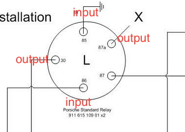 |
|
|
|
| nditiz1 |
Sep 3 2017, 07:01 PM
Post
#4
|
|
Senior Member Group: Members Posts: 1,188 Joined: 26-May 15 From: Mount Airy, Maryland Member No.: 18,763 Region Association: MidAtlantic Region |
Thanks guys. Can someone tell me what the 5th metal relay is and if my description of the others is correct? I see in the diagram there is a horn relay. Where is that located?
|
|
|
|
| Dave_Darling |
Sep 3 2017, 07:18 PM
Post
#5
|
|
914 Idiot Group: Members Posts: 14,990 Joined: 9-January 03 From: Silicon Valley / Kailua-Kona Member No.: 121 Region Association: Northern California |
The relays aren't exactly fixed in position. They could be swapped around during assembly, and sometimes were. The best way to tell which is which is to look at the colors of wires that go to the relay socket, and match that up with the wiring diagram.
The round relays are all the same. (With some exceptions that weren't used on 914s.) The two exceptions are the flasher relay, and the high-low relay. They aren't round, and they don't work like the others. The high-low relay is square, and changes which of two outputs it connects its input to when the signal pin gets grounded. The flasher relay is a taller box, and it intermittently connects its input to its output when there is power on the input and none on the output. It actually has two outputs and both get power at the same time, and it has a ground, but that's basically what it is doing. The round metal relay doesn't sound familiar. It might be a buzzer. What wires go to it? And what year is your car? --DD |
|
|
|
| nditiz1 |
Sep 3 2017, 07:49 PM
Post
#6
|
|
Senior Member Group: Members Posts: 1,188 Joined: 26-May 15 From: Mount Airy, Maryland Member No.: 18,763 Region Association: MidAtlantic Region |
Thanks Dave. Car is a 73.
I will pull the panel, trace the colored wires and get back to you |
|
|
|
| raynekat |
Sep 3 2017, 08:43 PM
Post
#7
|
|
Advanced Member Group: Members Posts: 2,159 Joined: 30-December 14 From: Coeur d'Alene, Idaho Member No.: 18,263 Region Association: Pacific Northwest |
QUOTE(oakdalecurtis @ Sep 3 2017, 08:48 AM)  ;Begin to familiarize yourself with these electrical diagrams. The more you study and use them, the easier it gets. These diagrams can answer all your continuity questions and provide wire colors to get you pointed in the right directions, electrically speaking... http://www.pelicanparts.com/914/914_electrical_diagrams.htm Here's a relay diagram: This diagram is not labeled totally correct in my mind. The 30 terminal is the power in. If there is no signal, then it is connected to the "deadhead" terminal 87a. In the relay socket, there is no wire going to 87a. This is also how you test these relays. With the relay in your hand, place a volt meter across terminals 30 and 87a. There should be continuity. If not, the relay is bad. Often times the 85 terminal goes to ground, but not always directly. The 86 terminal is where the signal comes in. With power to this terminal, a magnetic coil is activated that moves the direct connection for terminal 30 from 87 to 87a. In other words, when the relay gets it's signal through the 86 terminal, the power in at terminal 30 gets passed through to terminal 87, the output of this relay. PS... the round relay that only has 2 wires going to it is the buzzer for when you leave your keys in the ignition and the doors are open. |
|
|
|
| Tom_T |
Sep 4 2017, 07:43 PM
Post
#8
|
|
TMI.... Group: Members Posts: 8,318 Joined: 19-March 09 From: Orange, CA Member No.: 10,181 Region Association: Southern California |
Take a look at the diagrams on Jeff Bowlsby's 2 websites - under tach documents at the main classic 914 one + at the subsections of his 914 electrical harness rebuilding site.
|
|
|
|
|
1 User(s) are reading this topic (1 Guests and 0 Anonymous Users)
0 Members:

|
Lo-Fi Version | Time is now: 22nd May 2024 - 11:29 AM |
Invision Power Board
v9.1.4 © 2024 IPS, Inc.