|
|
|
Porsche, and the Porsche crest are registered trademarks of Dr. Ing. h.c. F. Porsche AG.
This site is not affiliated with Porsche in any way. Its only purpose is to provide an online forum for car enthusiasts. All other trademarks are property of their respective owners. |
|
|


| Larry.Hubby |
 Sep 22 2017, 12:17 AM Sep 22 2017, 12:17 AM
Post
#1
|
|
Member who doesn't post much, but has a long time in 914s  Group: Members Posts: 191 Joined: 24-November 04 From: Palo Alto, CA Member No.: 3,172 Region Association: Northern California |
One of the things I’ve always liked about the 914 is that it has plenty of space for its two intended occupants, especially a comfortable amount of leg room. Consequently, I’ve always disliked anything that infringes on this space, the factory center console and the under-dash evaporator unit of the dealer-installed A/C systems being prime examples. I have an early car, and I even disliked the change in ’72 to the fixed, rather than movable passenger’s foot rest because it made the leg room in the car seem less spacious. So, getting rid of the under-dash evaporator was a prime goal for my A/C system.
Not mounting the evaporator under the dash seems straightforward, just put it where the stock fresh air box is. That, after all, is where most cars with factory A/C locate their evaporators. Like many other things, however, this is much more easily said than done. The space the air box occupies turns out to be smaller than you might expect, particularly in the front to back direction. This by itself is not necessarily fatal, but it does restrict the choice of evaporator coils to very few existing ones from other cars, or to a custom-built one. For the one-off unit I was building for myself, a custom coil was pretty much out of the question. I don’t have the engineering expertise to specify such a coil that I could be confident would work without the design being iterated, perhaps several times, and the cost of having even one version made would probably be more than I’m willing to put out. Finding the design information one needs, particularly the external dimensions, of coils from other cars is difficult, since most all catalog information is organized by the car model that the replacement units fit, and dimensions and other engineering data are not necessary when dealing with exact replacements. So, I looked at after-market complete evaporator units designed for behind- rather than under-dash mounting, such as those from Vintage Air, and found them all to be too big. Next, I considered the evaporator units from other Porsche models that had/have A/C, starting with the 911 since the other models are water, rather than air, cooled, and this would mean that they incorporate a heater core, which would be useless in my case. The evaporator box from the 911 is also too large to fit, but the evaporator coil itself is very close to small enough. Looking at this further, I found that there are at least three versions of the 911 evaporator coil available on the replacement market, as shown below: 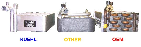 After some digging, I managed to obtain physical dimensions on these three units, and found that the Griffiths Kuehl coil is the smallest of the three, and that the difference is critical in that it is the only one that will fit between the gas tank and the wiper motor in a horizontal orientation with even a tiny amount of width left over for a box to enclose it. The Griffiths unit is also the most modern and efficient design, but also (one almost says ‘of course’) the most expensive at ~$500. Still, considering the potential for things not fitting or performing poorly after a lot of work to design and build a workable package around it, in my situation, the Griffiths unit is probably a bargain, and so that’s what I used. Even with an evaporator coil that will fit, designing a package that will fit, hook up to the stock air distribution system, and deliver acceptable air flow was not a trivial task. Once I had the size and shape of the evaporator coil determined, it was still a matter of juggling it, a blower with enough flow capability, air ducts to connect everything properly, and a means of reliably handling and eliminating condensation and rainwater that might enter the system and then fitting it all into the space available in such a way that the whole thing can physically be installed and removed when necessary. It rapidly became apparent that the main problem was the bulk of a centrifugal blower large enough to do the job. In the course of looking for an alternative, I finally found the unusually powerful Spal tube-axial fans (their P/N VA31-A101-46S), which, because of their compact size and straight-through air flow, seemed to offer a solution. That solution was to use the same basic air flow as the stock design, with outside air brought down from the openings in the cowl, through the fans, and into the air distribution boxes. In order to insert the evaporator coil in series with this stack, something had to shrink to provide room, and that something in this case was the air/water separation part of the inlet air box. The danger in doing this would be that there would be less of a slope to the floor of this upper part of the box, and so the rate at which water would run off under gravity would be reduced. This could be a problem if a deluge of water from heavy rain, or more likely a car wash, floods into the cowl air intake. If the rate of arrival of water is high enough and persists for long enough, water will overflow into the air intake and be forced through the fans and the evaporator coil. It would then land in the condensate collection space of the box and be ducted out to the same drain hose as the water separated by the upper part of the box. The only potential damage would be to the fans and/or the electronics that drive them, which, as you will see later, are mounted on the same platform as the fans. I live in California, and it doesn’t really rain here, for the last several years before this one, almost literally. Consequently, I have very little fear that my car will ever encounter such a deluge. I did attempt to measure the maximum safe runoff rate by pouring a pint of water into the upper section of the box, what I call the ‘shorty’ air box, and timing how quickly I could do that without causing the water level to continuously rise. The answer was about ten seconds. This would represent an incoming rate through the air intake of ¾ of a gallon/minute – probably safe even for a serious rain storm in a part of the country where it really rains or a commercial car wash. So, I envisioned my evaporator box to have three sections arranged like this: 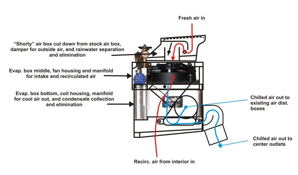 By cutting down the stock air box instead of building something new from scratch, I preserved the interface between it and the cowl and the stock gasket that seals this opening. However, since I was going to need absolutely all of the vertical room available, and since the air box is recessed into a cavity below the air intake openings, there was no way this entire package was going to slide into or out of position in one piece. The box would therefore need to be installed as two pieces. The shorty air box could be bolted into position via the stock mounting points, and the remainder of the assembly would be slid in horizontally below it. Fabricating the shorty air box involved cutting down the stock box, removing and re-mounting higher up the baffle that covers the air intake to the fan, fabricating a new sloped floor and air intake channel, and introducing a damper that can be operated from the outside and can close the intake when desired (like when you happen to be stopped at a light behind a roofer’s truck with a hot tar trailer in tow). The following photos show some of these steps: Air box jigged up for cutting on the band saw: 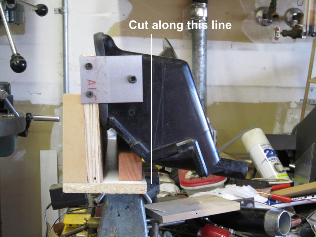 The cut part, with hole added on lower right for the rainwater drain: 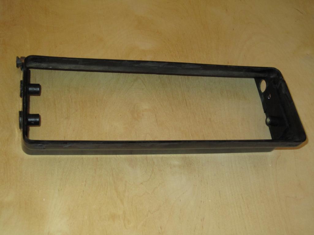 The same part with the central air duct and sloped floor added, damper (shown closed) in place with actuator rod exiting at one of mounting hole locations on passenger side, and the top baffle shown beside it cut from lower part of the original box for re-mounting above the air duct: 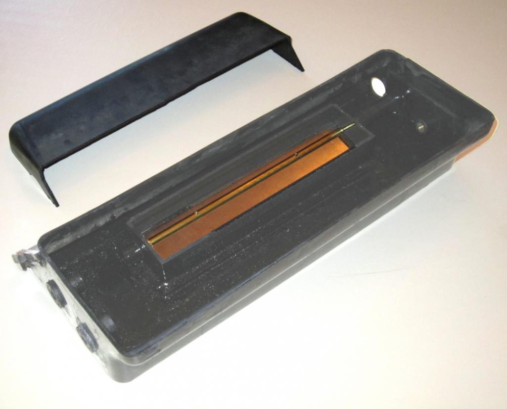 Top baffle added: 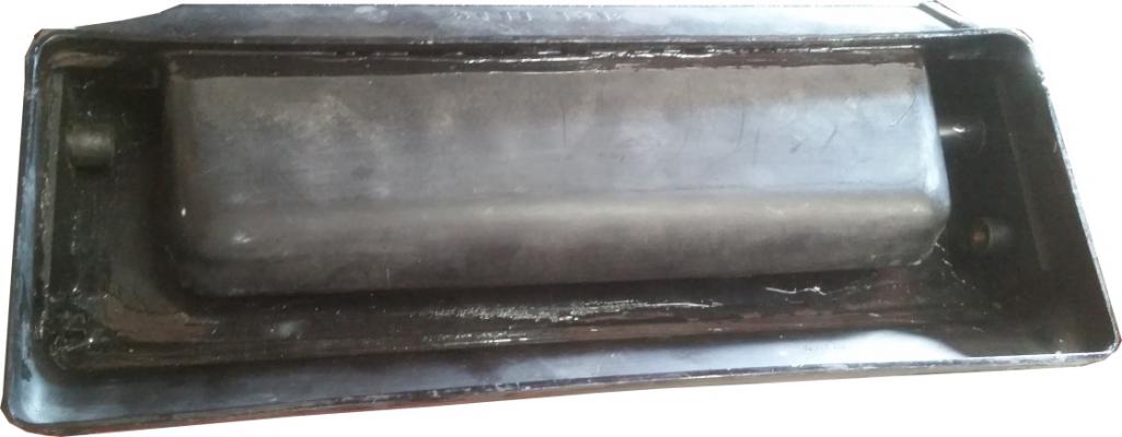 The whole shorty box completed: 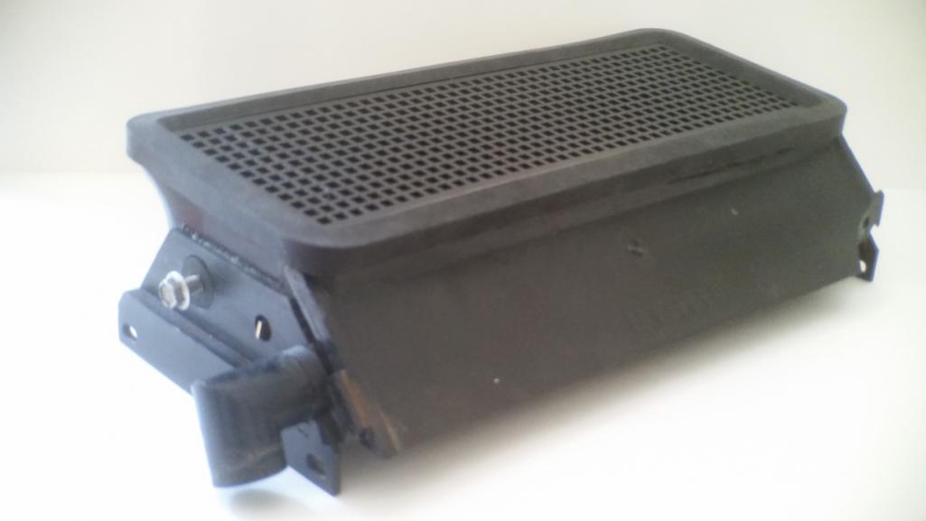 The factory air box is made from ABS plastic, so vacuum-formed ABS is an obvious candidate for constructing the other two sections of the evaporator box. However, space is so tight that deep, vertical sides are called for, and consequently there isn’t room to build a reasonable taper into the parts to make them easy to separate from the mold. Also, deep enough draws are required that it will be difficult to eliminate webbing at the corners unless one uses a female mold. Although I have access to a vacuum forming machine, my skill level with it is not high, and after several unsuccessful attempts to produce a female mold for the bottom part of the box, and in consideration that I was building after all only one unit, I gave up and decided to build the box sections from flat pieces simply glued together, heavily reinforcing the corners with square or triangular cross-section rods and taking the attitude that ABS glue is my friend – there is no such thing as too much. The photo below is of the bottom section of the box, looking down into the interior. It’s a bit difficult to see because everything is black, but there is a shelf on either end to support the coil above the central space for condensate collection. The floor of this part is sloped toward the upper right corner in the picture, where there is a drain hole that feeds into the same hose that ducts rainwater out from the top section. The white and black air ducts on either end are 3D printed transitions that duct the cooled air from oval outlets in the walls of the box just below the coil shelves and above the floor of the condensate collection area to the stock air distribution boxes. The shiny metal parts are baffles of thin stainless sheet metal at each cool air outlet that are intended to block any condensate from sloshing into the outlets under hard braking or cornering. 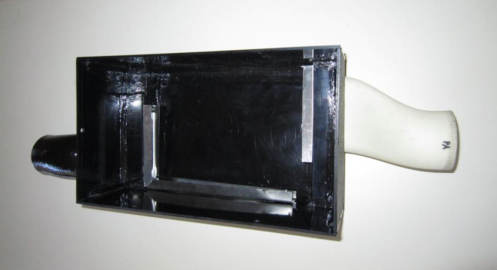 The evaporator coil then fits into the box like this: 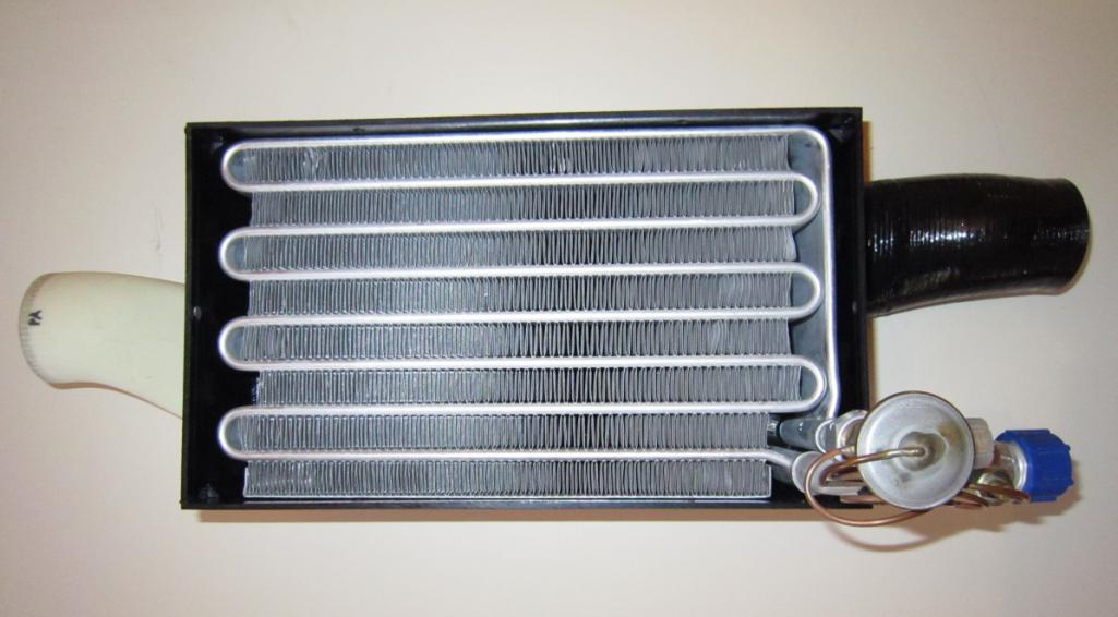 The fans and their electronics are mounted on an aluminum deck that fits immediately above the coil: 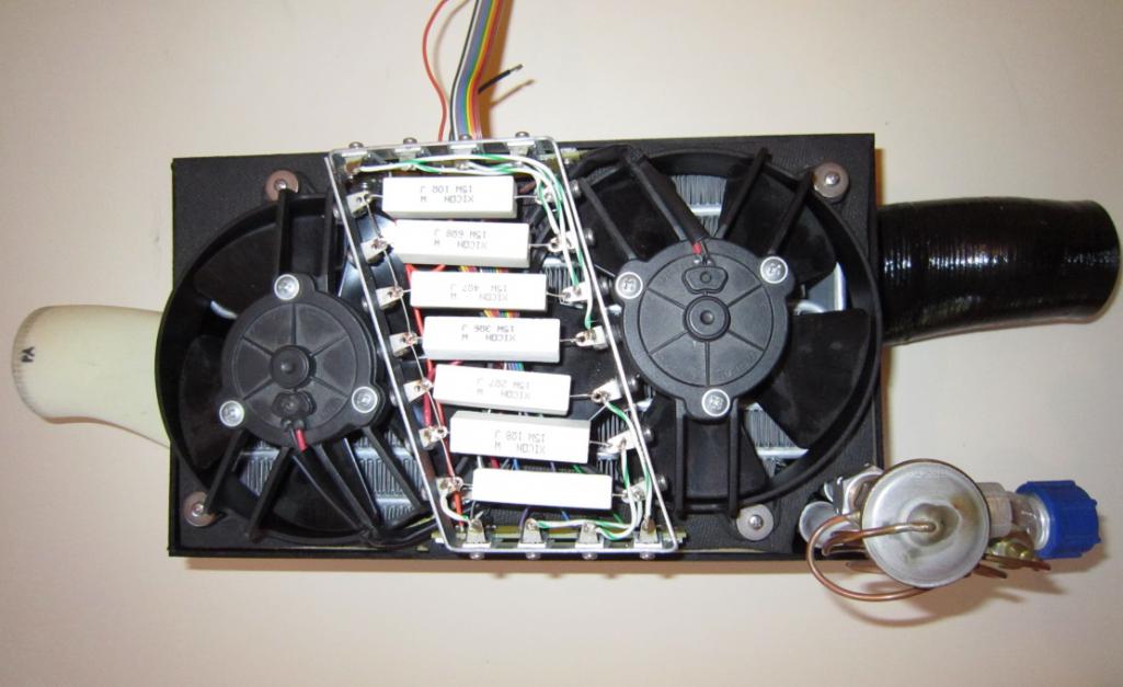 The middle section is the simplest, being just an enclosure for the fans and a manifold of sorts for the incoming air. This photo shows the assembled top and middle box sections from the bottom. The large rectangular opening in the middle is the fresh air inlet from the shorty air box, the 3” round duct at the right is the recirculation air inlet, and the quarter circular notch out of the upper right corner is to clear the inlet/outlet fittings and the expansion valve of the coil. 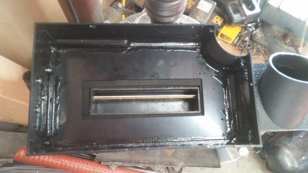 Here is a view of the assembled box on my mock-up prior to installation in the car: 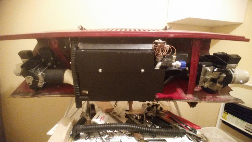 Once everything’s back in the car, very little that’s non-stock is visible: 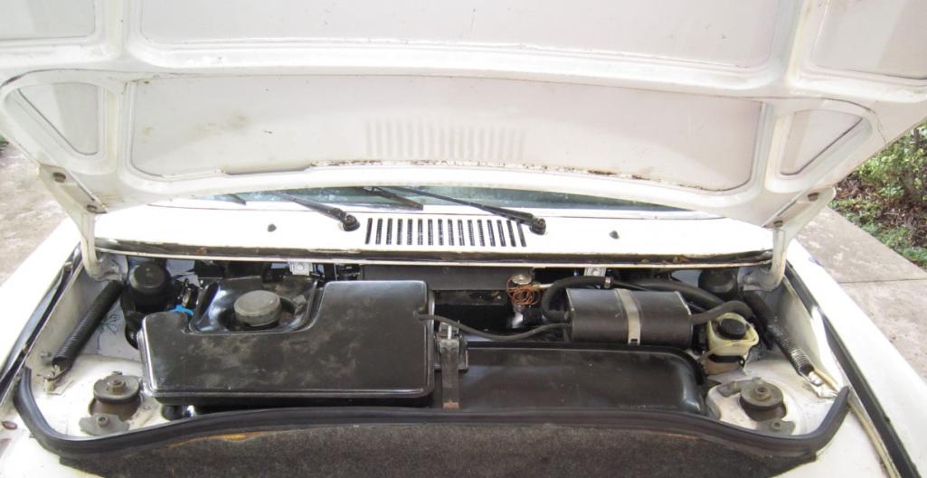 I did run air flow tests to compare what my system was going to put out to what the AC in my 2010 Honda Accord sedan provides and came up with the following numbers for total air flow with the blower set to maximum in each case: Honda air flow = 119.2cfm, cabin volume = 94cf; 914 air flow = 92.4cfm, cabin volume = 46cf. So, with about 80% of the air flow, but about half the cabin volume, the 914 should actually deliver better effective cooling to its occupants than does the Honda. After living with the car with the system working for a few weeks, I can say that this does indeed seem to be true. |
   |

 
|
Posts in this topic
 Larry Hubby AC for My Six Conversion Sep 22 2017, 12:17 AM
 Beebo Kanelle Brilliant! Sep 22 2017, 04:35 AM
 amfab
Brilliant!
:agree: Sep 22 2017, 08:56 PM mepstein Once your done, this should be added to the classi... Sep 22 2017, 05:46 AM Philip W. so cool someone is finally putting this together -... Sep 22 2017, 07:19 AM GeorgeRud Amazing work! I applaud your design and fabri... Sep 22 2017, 09:03 AM Andyrew Thats awesome! Many of us have dreamed of doin... Sep 22 2017, 09:33 AM Steve Larry,
Are you going to put together a parts list ... Sep 22 2017, 07:18 PM 914forme :agree:
Or do a kit
:Qarl: Sep 22 2017, 08:13 PM Larry Hubby Thanks for the positive response everyone. I... Sep 22 2017, 08:47 PM djway What size refrigerant lines did you use in the var... Nov 18 2017, 02:52 AM larryM NICE!
now let's see your engine mount ... Nov 18 2017, 12:20 PM Larry Hubby djway, I used the fairly standard -6 hose for the ... Nov 19 2017, 01:34 AM djway
djway, I used the fairly standard -6 hose for the... Nov 19 2017, 01:16 PM Larry Hubby djway,
Have you looked at Cold Hose in Florida,
... Nov 19 2017, 09:57 PM djway
djway,
Have you looked at Cold Hose in Florida,
... Nov 19 2017, 10:18 PM Mowog4 This is beyond awesome, I can't wait to try it... Nov 29 2017, 06:32 PM
amfab
Brilliant!
:agree: Sep 22 2017, 08:56 PM mepstein Once your done, this should be added to the classi... Sep 22 2017, 05:46 AM Philip W. so cool someone is finally putting this together -... Sep 22 2017, 07:19 AM GeorgeRud Amazing work! I applaud your design and fabri... Sep 22 2017, 09:03 AM Andyrew Thats awesome! Many of us have dreamed of doin... Sep 22 2017, 09:33 AM Steve Larry,
Are you going to put together a parts list ... Sep 22 2017, 07:18 PM 914forme :agree:
Or do a kit
:Qarl: Sep 22 2017, 08:13 PM Larry Hubby Thanks for the positive response everyone. I... Sep 22 2017, 08:47 PM djway What size refrigerant lines did you use in the var... Nov 18 2017, 02:52 AM larryM NICE!
now let's see your engine mount ... Nov 18 2017, 12:20 PM Larry Hubby djway, I used the fairly standard -6 hose for the ... Nov 19 2017, 01:34 AM djway
djway, I used the fairly standard -6 hose for the... Nov 19 2017, 01:16 PM Larry Hubby djway,
Have you looked at Cold Hose in Florida,
... Nov 19 2017, 09:57 PM djway
djway,
Have you looked at Cold Hose in Florida,
... Nov 19 2017, 10:18 PM Mowog4 This is beyond awesome, I can't wait to try it... Nov 29 2017, 06:32 PM  |
1 User(s) are reading this topic (1 Guests and 0 Anonymous Users)
0 Members:

|
Lo-Fi Version | Time is now: 2nd April 2026 - 10:00 AM |
Invision Power Board
v9.1.4 © 2026 IPS, Inc.