|
|
|
Porsche, and the Porsche crest are registered trademarks of Dr. Ing. h.c. F. Porsche AG.
This site is not affiliated with Porsche in any way. Its only purpose is to provide an online forum for car enthusiasts. All other trademarks are property of their respective owners. |
|
|


| doug_b_928 |
 Jan 31 2018, 03:55 PM Jan 31 2018, 03:55 PM
Post
#41
|
|
Senior Member  Group: Members Posts: 714 Joined: 17-January 13 From: Winnipeg Member No.: 15,382 Region Association: Canada |
My main Winter project is to 'restore' the wiring harness on my 73. I admit that of all the jobs involved in restoring this car, this is the one that creates the most anxiety in me. I took it out of it's container last winter, spread it out on the floor, and promptly proceeded to put it back in the container. But, the time has come to conquer this thing. I have 4 rolls of wire tape that cost more to ship to me than the tape itself, and I think everything I need to do the job. I have pieces of a 74 harness (which I'm aware is not the same) and have already used one of the correct connectors from it for one of the license plate light connectors. Overall, I think the harness could be a lot worse, but there are some areas where POs have made some modifications/fixes and I'm not sure what they've done and why. I'll be asking for assistance from the wiring gurus in the thread as I work my way through. I have the wiring diagram from Jeff Bowlsby's website, a multimeter, PowerProbe3, and cleaning supplies. I'm removing all the tape, inspecting, cleaning, and then installing new tape. I'm just going to clean and inspect the rubber covered sheaths as they seem to be tight around the wires and it seems unlikely that there is anything wrong underneath them (on the upside, everything that ever worked on the car during my ownership, which wasn't everything that was supposed to, still did right before I removed the harness).
Okay, so with that introduction, my first questions. Starting at the back, I've worked my way through the license plate wires, to the trunk light wires, and I'm currently looking at the fuel pump wires. My car had vapor lock, so the fuel pump was relocated to the front of the car. The mechanic just cut the wires, left the ground wire dangling, and spliced in a positive wire which he ran through the firewall (poking a hole; no grommet), under the carpet and through a hole in the front firewall, where he then spliced in the connector and grounded to a screw he added to the front firewall. Here's a pic of the wires: 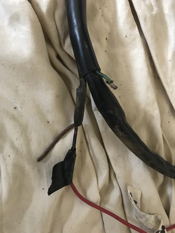 Because of the vapor lock issue, I'm thinking I should put my new pump in the front where the old one was (by the steering rack). I'm thinking of getting the NAPA Bosch fuel pump (N69133). From what I can tell looking at the wiring diagram, and I could be reading it wrong, the power wire goes to the 'regulator/relay plate). If it's source was at the fuse box under the dash I'd splice into the wire up there and put the original connector back on the wires in the engine bay (in case I ever wanted to put an original style in its original spot. If I'm correct about the wiring diagram, then, with my limited knowledge, I guess I have to run the power wire on the outside of the sheath (but at least it will be inside the new 914 rubber snorkel) and up to the fuel pump in the front? Is there any point in running the ground wire that way too, or would you just ground it to a screw on the car as it was before? Also, in the pic above there is a green wire that looks like it had a connector on it at one time. Does anyone know what that was for? When I look at the 73 diagram it only shows the black with red dots and the ground for the fuel pump. On the diagram it shows the, IIRC, 'fan blower motor' having a green wire. However, if that's referring to the blower motor for the heater, I think the wires and connector below were for that (note no green wire). 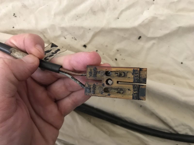 So, to summarize, what's the best approach for the fuel pump wiring, and what is that green wire for? |
   |

 
|
Posts in this topic
 doug_b_928 Assistance with Restoring 73 Wiring Harness Jan 31 2018, 03:55 PM
 dr914@autoatlanta.com cannot tell much from the pics but if it is a gree... Jan 31 2018, 05:11 PM simonjb As an aside, you can buy those connectors from Bug... Jan 31 2018, 05:45 PM bbrock
cannot tell much from the pics but if it is a gre... Jan 31 2018, 05:55 PM earossi There is a guy over on the Pelican Engine Rebuildi... Jan 31 2018, 06:15 PM
dr914@autoatlanta.com cannot tell much from the pics but if it is a gree... Jan 31 2018, 05:11 PM simonjb As an aside, you can buy those connectors from Bug... Jan 31 2018, 05:45 PM bbrock
cannot tell much from the pics but if it is a gre... Jan 31 2018, 05:55 PM earossi There is a guy over on the Pelican Engine Rebuildi... Jan 31 2018, 06:15 PM
 mepstein
There is a guy over on the Pelican Engine Rebuild... Jan 31 2018, 06:21 PM earossi
There is a guy over on the Pelican Engine Rebuil... Jan 31 2018, 08:23 PM mepstein
[quote name='mepstein' post='2573750' date='Jan 3... Jan 31 2018, 08:49 PM earossi
[quote name='mepstein' post='2573750' date='Jan ... Feb 3 2018, 04:03 PM porschetub Dennis isn't doing full 914 looms or he told m... Feb 3 2018, 11:54 PM Jeff Bowlsby When relocating the FP to the front note that the ... Jan 31 2018, 06:20 PM malcolm2 Hope I am not too late. But I bought one of these... Jan 31 2018, 06:27 PM doug_b_928 Wow! Thank you to all of you for your helpful... Jan 31 2018, 06:49 PM bbrock
Brent, I think I'll have to study your postin... Jan 31 2018, 06:59 PM gothspeed I am just about completed bringing my 73' harn... Jan 31 2018, 06:59 PM doug_b_928 So, using my spare harness pieces, I found the mat... Feb 3 2018, 12:47 PM Dave_Darling A coat-hanger will poke through the snorkel. If y... Feb 3 2018, 01:29 PM bbrock
A coat-hanger will poke through the snorkel. If ... Feb 3 2018, 02:27 PM Jeff Bowlsby Umm...
The 1975-76 schematic indicates that the F... Feb 3 2018, 02:47 PM doug_b_928 Hmmm...So you're suggesting to pull the FP wir... Feb 3 2018, 03:17 PM bbrock
Hmmm...So you're suggesting to pull the FP wi... Feb 3 2018, 03:22 PM doug_b_928 Awesome Brent, thanks! Feb 3 2018, 03:24 PM doug_b_928 Until today I haven't had any time for this pr... Feb 11 2018, 12:38 PM bbrock I haven't had to remove that one yet, but I be... Feb 11 2018, 02:04 PM Jeff Bowlsby Its a female hollow tube terminal extractor. I ha... Feb 11 2018, 02:29 PM doug_b_928 Thanks guys. I was able to clean the connectors w... Feb 11 2018, 04:39 PM doug_b_928 @ Brent...Yes, they are from a label maker. I bou... Feb 11 2018, 04:43 PM doug_b_928 update: I see the unknown ground goes to the grou... Feb 11 2018, 05:05 PM Jeff Bowlsby See wire 63 on the second page of the schematic. ... Feb 11 2018, 07:01 PM doug_b_928 Got it. Thanks Jeff!
Looks like I'm th... Feb 11 2018, 07:17 PM 914_teener
Got it. Thanks Jeff!
Looks like I'm t... Feb 11 2018, 11:06 PM Dave_Darling Black to the single terminal on the left. Brown t... Feb 11 2018, 10:35 PM doug_b_928 Thanks guys. Now I just need to find some of thos... Feb 12 2018, 08:30 AM bbrock
Thanks guys. Now I just need to find some of tho... Feb 12 2018, 09:38 AM doug_b_928 Thanks very much Brent. Do you know how to identi... Feb 12 2018, 09:44 AM bbrock
Thanks very much Brent. Do you know how to ident... Feb 12 2018, 10:04 AM gothspeed The white striped ground wire comes from the drive... Feb 12 2018, 10:04 AM doug_b_928 Awesome, thanks! Feb 12 2018, 01:16 PM doug_b_928 Thanks to Brent I'll be ordering new connector... Feb 13 2018, 09:25 PM doug_b_928 Another quicker question: I think my car has the ... Feb 13 2018, 09:54 PM bbrock IIRC, there is only a positive wire to the heater ... Feb 14 2018, 12:05 AM doug_b_928 Thanks as always, Brent. I appreciate you checkin... Feb 14 2018, 09:05 AM bbrock Just looked at my harness and confirmed only one w... Feb 14 2018, 09:30 AM doug_b_928 Thanks, Brent. That also gives me a sense of how ... Feb 14 2018, 09:53 AM bbrock
Thanks, Brent. That also gives me a sense of how... Feb 14 2018, 10:05 AM bbrock Ah! I just looked at the schematic and it loo... Feb 14 2018, 12:50 PM doug_b_928 Exactly, so I figure I'll just make up a singl... Feb 14 2018, 01:19 PM bbrock
Exactly, so I figure I'll just make up a sing... Feb 14 2018, 06:12 PM doug_b_928 Brent, that was an awesome tip re digikey and than... Feb 17 2018, 09:29 AM doug_b_928 Upon further investigation, things make a bit more... Feb 17 2018, 12:27 PM doug_b_928 Today's question: I think I've figured out... Feb 18 2018, 10:59 AM bbrock
Today's question: I think I've figured ou... Feb 18 2018, 01:35 PM gothspeed
Today's question: I think I've figured ou... Feb 21 2018, 06:53 PM Jeff Bowlsby Fellas, its a circuit. From the power wire, throu... Feb 18 2018, 04:06 PM doug_b_928 Makes sense, thanks Jeff!
PS. Does the mystery... Feb 18 2018, 04:12 PM Jeff Bowlsby Don't know about the mystery harness. It may ... Feb 18 2018, 04:18 PM doug_b_928 Perfect, thanks Jeff! Feb 18 2018, 04:21 PM doug_b_928 My extremely limited knowledge of electronics cont... Feb 21 2018, 08:06 AM doug_b_928 Hoping someone will chime in about my previous pos... Feb 21 2018, 06:36 PM doug_b_928 I just searched some old pictures and it appears t... Feb 21 2018, 06:46 PM bbrock
I just searched some old pictures and it appears ... Feb 21 2018, 07:45 PM doug_b_928 Thanks very much Brent. Yeah, after all of this I... Feb 23 2018, 07:44 PM Jeff Bowlsby If my memory is right the radio clips to Fuse #7 b... Feb 23 2018, 08:05 PM bbrock
3. A PO had installed an electric motor for the W... Feb 23 2018, 11:49 PM doug_b_928 Did a little searching and see that there was not ... Feb 23 2018, 07:58 PM doug_b_928 Thanks very much as always Jeff. I'll await y... Feb 23 2018, 08:41 PM Jeff Bowlsby I know I have seen a harness with the radio at fus... Feb 23 2018, 08:56 PM doug_b_928 Thanks again Jeff!
As an update, here's a... Feb 23 2018, 09:01 PM Jeff Bowlsby Looks good. Hope you see now why I don't reco... Feb 23 2018, 09:44 PM doug_b_928 Thanks Jeff. So to make sure, no fire issues with... Feb 23 2018, 09:49 PM Jeff Bowlsby I would not label them permanently, but I see no h... Feb 23 2018, 10:10 PM doug_b_928 Excellent, thanks Jeff. I'm leaving them for ... Feb 23 2018, 10:16 PM doug_b_928 Thanks for WW fluid system explanation, Brent. Do... Feb 24 2018, 05:46 AM doug_b_928 Update: I’ve added a couple pieces of wire (loo... Feb 24 2018, 10:05 AM doug_b_928 Technical question: the small black with blue wir... Feb 24 2018, 02:35 PM doug_b_928 Winter job done (with the exceptions of needing to... Feb 25 2018, 10:19 PM bbrock :trophy: :cheer: Feb 25 2018, 11:18 PM doug_b_928 Thanks Brent. There are two questions that I forg... Feb 26 2018, 08:47 AM doug_b_928 Update re testing a diode: I found this youtube v... Feb 26 2018, 10:19 AM
mepstein
There is a guy over on the Pelican Engine Rebuild... Jan 31 2018, 06:21 PM earossi
There is a guy over on the Pelican Engine Rebuil... Jan 31 2018, 08:23 PM mepstein
[quote name='mepstein' post='2573750' date='Jan 3... Jan 31 2018, 08:49 PM earossi
[quote name='mepstein' post='2573750' date='Jan ... Feb 3 2018, 04:03 PM porschetub Dennis isn't doing full 914 looms or he told m... Feb 3 2018, 11:54 PM Jeff Bowlsby When relocating the FP to the front note that the ... Jan 31 2018, 06:20 PM malcolm2 Hope I am not too late. But I bought one of these... Jan 31 2018, 06:27 PM doug_b_928 Wow! Thank you to all of you for your helpful... Jan 31 2018, 06:49 PM bbrock
Brent, I think I'll have to study your postin... Jan 31 2018, 06:59 PM gothspeed I am just about completed bringing my 73' harn... Jan 31 2018, 06:59 PM doug_b_928 So, using my spare harness pieces, I found the mat... Feb 3 2018, 12:47 PM Dave_Darling A coat-hanger will poke through the snorkel. If y... Feb 3 2018, 01:29 PM bbrock
A coat-hanger will poke through the snorkel. If ... Feb 3 2018, 02:27 PM Jeff Bowlsby Umm...
The 1975-76 schematic indicates that the F... Feb 3 2018, 02:47 PM doug_b_928 Hmmm...So you're suggesting to pull the FP wir... Feb 3 2018, 03:17 PM bbrock
Hmmm...So you're suggesting to pull the FP wi... Feb 3 2018, 03:22 PM doug_b_928 Awesome Brent, thanks! Feb 3 2018, 03:24 PM doug_b_928 Until today I haven't had any time for this pr... Feb 11 2018, 12:38 PM bbrock I haven't had to remove that one yet, but I be... Feb 11 2018, 02:04 PM Jeff Bowlsby Its a female hollow tube terminal extractor. I ha... Feb 11 2018, 02:29 PM doug_b_928 Thanks guys. I was able to clean the connectors w... Feb 11 2018, 04:39 PM doug_b_928 @ Brent...Yes, they are from a label maker. I bou... Feb 11 2018, 04:43 PM doug_b_928 update: I see the unknown ground goes to the grou... Feb 11 2018, 05:05 PM Jeff Bowlsby See wire 63 on the second page of the schematic. ... Feb 11 2018, 07:01 PM doug_b_928 Got it. Thanks Jeff!
Looks like I'm th... Feb 11 2018, 07:17 PM 914_teener
Got it. Thanks Jeff!
Looks like I'm t... Feb 11 2018, 11:06 PM Dave_Darling Black to the single terminal on the left. Brown t... Feb 11 2018, 10:35 PM doug_b_928 Thanks guys. Now I just need to find some of thos... Feb 12 2018, 08:30 AM bbrock
Thanks guys. Now I just need to find some of tho... Feb 12 2018, 09:38 AM doug_b_928 Thanks very much Brent. Do you know how to identi... Feb 12 2018, 09:44 AM bbrock
Thanks very much Brent. Do you know how to ident... Feb 12 2018, 10:04 AM gothspeed The white striped ground wire comes from the drive... Feb 12 2018, 10:04 AM doug_b_928 Awesome, thanks! Feb 12 2018, 01:16 PM doug_b_928 Thanks to Brent I'll be ordering new connector... Feb 13 2018, 09:25 PM doug_b_928 Another quicker question: I think my car has the ... Feb 13 2018, 09:54 PM bbrock IIRC, there is only a positive wire to the heater ... Feb 14 2018, 12:05 AM doug_b_928 Thanks as always, Brent. I appreciate you checkin... Feb 14 2018, 09:05 AM bbrock Just looked at my harness and confirmed only one w... Feb 14 2018, 09:30 AM doug_b_928 Thanks, Brent. That also gives me a sense of how ... Feb 14 2018, 09:53 AM bbrock
Thanks, Brent. That also gives me a sense of how... Feb 14 2018, 10:05 AM bbrock Ah! I just looked at the schematic and it loo... Feb 14 2018, 12:50 PM doug_b_928 Exactly, so I figure I'll just make up a singl... Feb 14 2018, 01:19 PM bbrock
Exactly, so I figure I'll just make up a sing... Feb 14 2018, 06:12 PM doug_b_928 Brent, that was an awesome tip re digikey and than... Feb 17 2018, 09:29 AM doug_b_928 Upon further investigation, things make a bit more... Feb 17 2018, 12:27 PM doug_b_928 Today's question: I think I've figured out... Feb 18 2018, 10:59 AM bbrock
Today's question: I think I've figured ou... Feb 18 2018, 01:35 PM gothspeed
Today's question: I think I've figured ou... Feb 21 2018, 06:53 PM Jeff Bowlsby Fellas, its a circuit. From the power wire, throu... Feb 18 2018, 04:06 PM doug_b_928 Makes sense, thanks Jeff!
PS. Does the mystery... Feb 18 2018, 04:12 PM Jeff Bowlsby Don't know about the mystery harness. It may ... Feb 18 2018, 04:18 PM doug_b_928 Perfect, thanks Jeff! Feb 18 2018, 04:21 PM doug_b_928 My extremely limited knowledge of electronics cont... Feb 21 2018, 08:06 AM doug_b_928 Hoping someone will chime in about my previous pos... Feb 21 2018, 06:36 PM doug_b_928 I just searched some old pictures and it appears t... Feb 21 2018, 06:46 PM bbrock
I just searched some old pictures and it appears ... Feb 21 2018, 07:45 PM doug_b_928 Thanks very much Brent. Yeah, after all of this I... Feb 23 2018, 07:44 PM Jeff Bowlsby If my memory is right the radio clips to Fuse #7 b... Feb 23 2018, 08:05 PM bbrock
3. A PO had installed an electric motor for the W... Feb 23 2018, 11:49 PM doug_b_928 Did a little searching and see that there was not ... Feb 23 2018, 07:58 PM doug_b_928 Thanks very much as always Jeff. I'll await y... Feb 23 2018, 08:41 PM Jeff Bowlsby I know I have seen a harness with the radio at fus... Feb 23 2018, 08:56 PM doug_b_928 Thanks again Jeff!
As an update, here's a... Feb 23 2018, 09:01 PM Jeff Bowlsby Looks good. Hope you see now why I don't reco... Feb 23 2018, 09:44 PM doug_b_928 Thanks Jeff. So to make sure, no fire issues with... Feb 23 2018, 09:49 PM Jeff Bowlsby I would not label them permanently, but I see no h... Feb 23 2018, 10:10 PM doug_b_928 Excellent, thanks Jeff. I'm leaving them for ... Feb 23 2018, 10:16 PM doug_b_928 Thanks for WW fluid system explanation, Brent. Do... Feb 24 2018, 05:46 AM doug_b_928 Update: I’ve added a couple pieces of wire (loo... Feb 24 2018, 10:05 AM doug_b_928 Technical question: the small black with blue wir... Feb 24 2018, 02:35 PM doug_b_928 Winter job done (with the exceptions of needing to... Feb 25 2018, 10:19 PM bbrock :trophy: :cheer: Feb 25 2018, 11:18 PM doug_b_928 Thanks Brent. There are two questions that I forg... Feb 26 2018, 08:47 AM doug_b_928 Update re testing a diode: I found this youtube v... Feb 26 2018, 10:19 AM  |
1 User(s) are reading this topic (1 Guests and 0 Anonymous Users)
0 Members:

|
Lo-Fi Version | Time is now: 16th July 2025 - 07:12 PM |
Invision Power Board
v9.1.4 © 2025 IPS, Inc.