|
|
|
Porsche, and the Porsche crest are registered trademarks of Dr. Ing. h.c. F. Porsche AG.
This site is not affiliated with Porsche in any way. Its only purpose is to provide an online forum for car enthusiasts. All other trademarks are property of their respective owners. |
|
|

  |

| TravisNeff |
 Jan 29 2019, 08:32 AM Jan 29 2019, 08:32 AM
Post
#41
|
|
914 Guru  Group: Members Posts: 5,082 Joined: 20-March 03 From: Mesa, AZ Member No.: 447 Region Association: Southwest Region |
How did you get the car up onto the rotisserie? I always wonder how this is done without a lift.
|
   |

 
|
| Joemo5 |
Jan 29 2019, 07:13 PM
Post
#42
|
|
Member Group: Members Posts: 54 Joined: 1-April 18 From: Charlotte, North Carolina Member No.: 22,011 Region Association: South East States |
|
|
|
|
| Joemo5 |
Jan 29 2019, 07:36 PM
Post
#43
|
|
Member Group: Members Posts: 54 Joined: 1-April 18 From: Charlotte, North Carolina Member No.: 22,011 Region Association: South East States |
QUOTE(TravisNeff @ Jan 29 2019, 09:32 AM)  How did you get the car up onto the rotisserie? I always wonder how this is done without a lift. A few buddies lifted and another pushed the stand onto the pivot. Once stripped, these cars don't weigh much at all. |
|
|
|
| ConeDodger |
Jan 30 2019, 10:59 AM
Post
#44
|
|
Apex killer! Group: Members Posts: 24,100 Joined: 31-December 04 From: Tahoe Area Member No.: 3,380 Region Association: Northern California |
@pete000 needs to get involved here I think...
|
|
|
|
| Joemo5 |
Mar 3 2019, 11:37 PM
Post
#45
|
|
Member Group: Members Posts: 54 Joined: 1-April 18 From: Charlotte, North Carolina Member No.: 22,011 Region Association: South East States |
I've spent a day drilling out spot welds and got part of the floor pan removed. I didn't want to remove all of the front portion until I knew how far up the replacement went. A rather large order to Restoration Design is in my future.
Here's the removed section. "Rust bucket" is an appropriate description. 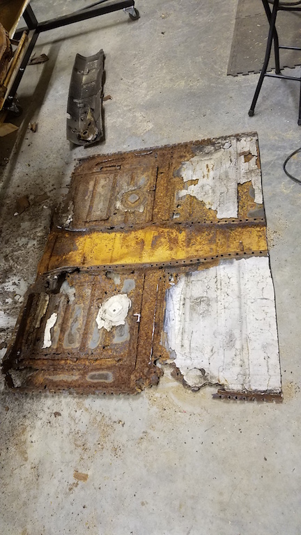 Here's the car 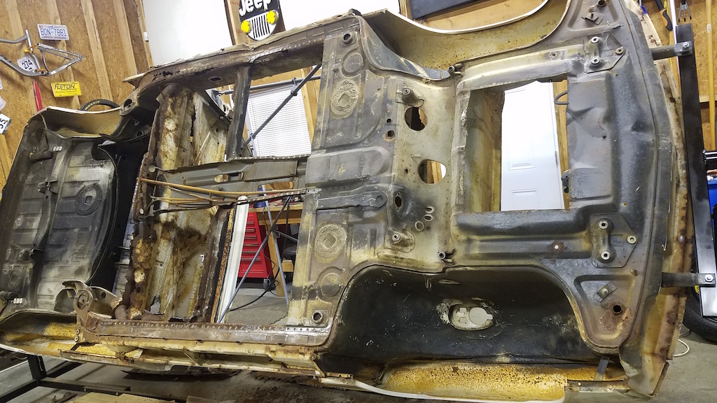 As I mentioned before, the most concerning portion of the car is the passenger longitudinal. Looking at this, I'm not sure how the car didn't sag or have misaligned door gaps. 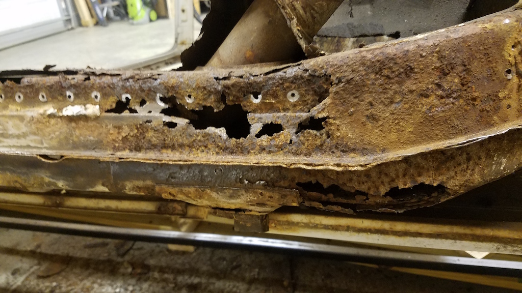 The rotisserie has been extremely convienent but I still worry about the two halves moving or becoming misaligned since both the inner and outer portion of the longitudinal have to be replaced. I'm thinking about tying the front suspension points to the rear suspension console via a brace of some sort. "Temporary frame rails" if you will. Of course, if either suspension console needs to be replaced this idea is useless. Here's a look into that hole in the passenger longitudinal, looking back at the suspension console. The rust doesn't look nearly as bad as I had imagined near the suspension console. 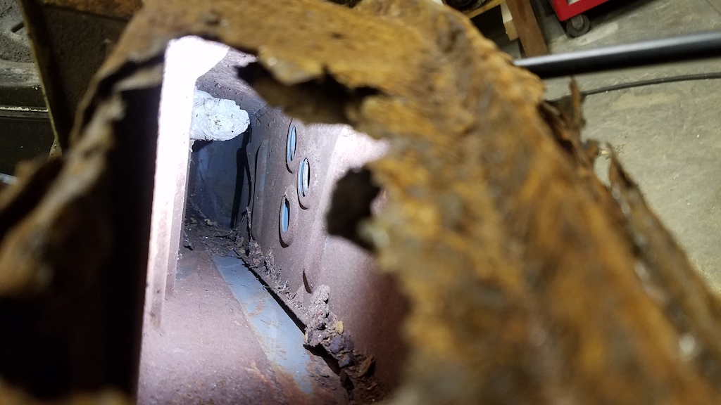 |
|
|
|
| Joemo5 |
May 20 2019, 06:35 PM
Post
#46
|
|
Member Group: Members Posts: 54 Joined: 1-April 18 From: Charlotte, North Carolina Member No.: 22,011 Region Association: South East States |
Several updates: Bought the major frame rail components from Restoration Design.
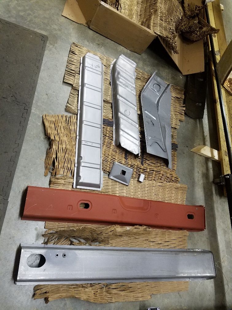 Built a lower support structure that ties the front and rear suspension points together. 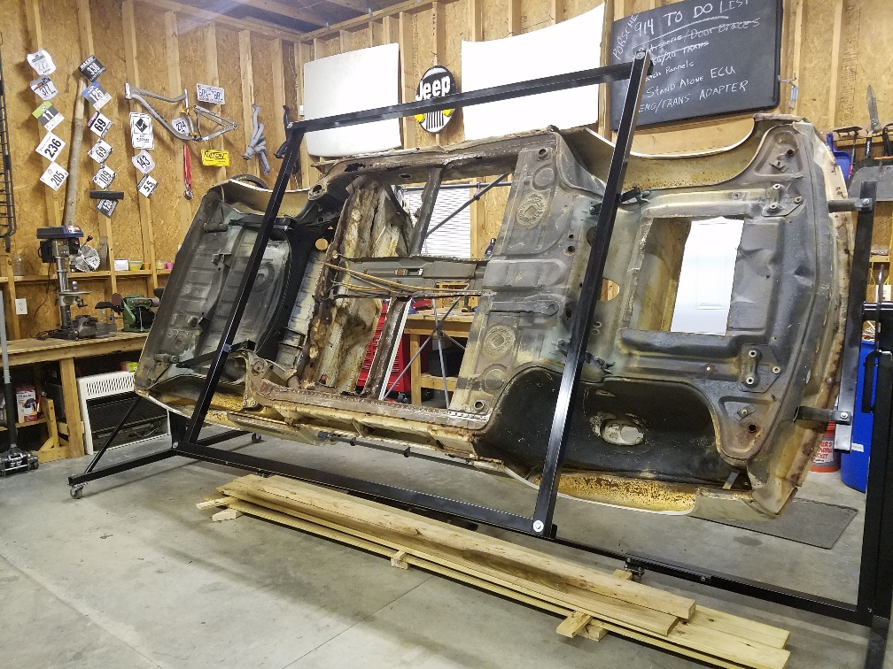 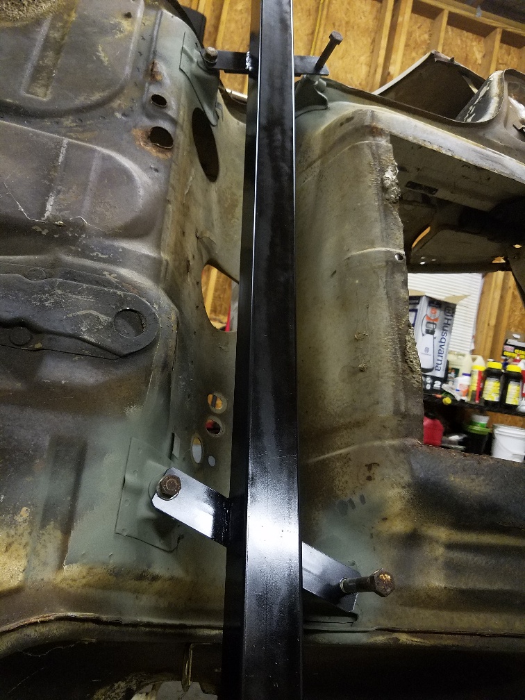 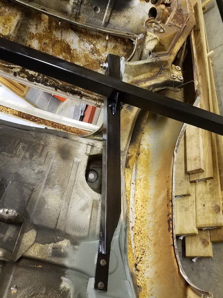 The idea here is to add additional support when the frame rails are cut out, and be able to test the torsional rigidity of the chassis as modifications are made. The rails that are parallel to the longs can be removed. Using the remaining rails should allow me to twist the car and measure the deflection. I really want to know what I'm getting when I make mods. Of course I wont do any of this testing until the rotten longs are repaired so that the chassis isnt permanently twisted out of wack. Stiffening mods planned: Seam welding, roll cage, structural foam? and longitudinal stiffening. Here's where I want input: Has anyone done any sort of internal stiffening for the longs on the 914? My primary goal is safety. Think side impact with a SUV. Second goal is minimal weight added and third is improved handling from a stiffer chassis. I want to thank those who have shared the kits that weld on the outside or inner of longs. Those are still on the table. I found some really interesting stuff about structural foams used on Infinity brand cars but I'm not at that point yet. I'm planning on running the water lines down the inside of the frame rails and wondered if a metal tube liner that was welded at each end along with cross sections could add some stiffness. |
|
|
|
| Joemo5 |
Aug 24 2019, 06:55 PM
Post
#47
|
|
Member Group: Members Posts: 54 Joined: 1-April 18 From: Charlotte, North Carolina Member No.: 22,011 Region Association: South East States |
I really need to update more frequently..
So I took the plunge and just cut out a large section of the rotten frame rail. (IMG:style_emoticons/default/sawzall-smiley.gif) The idea here is that I can look back at it in one piece to see how the replacements should fit. Here's some pics that show the process with before and after. Looking at the outside: 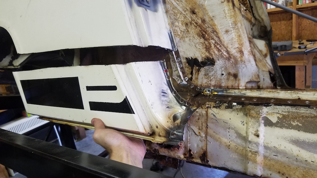 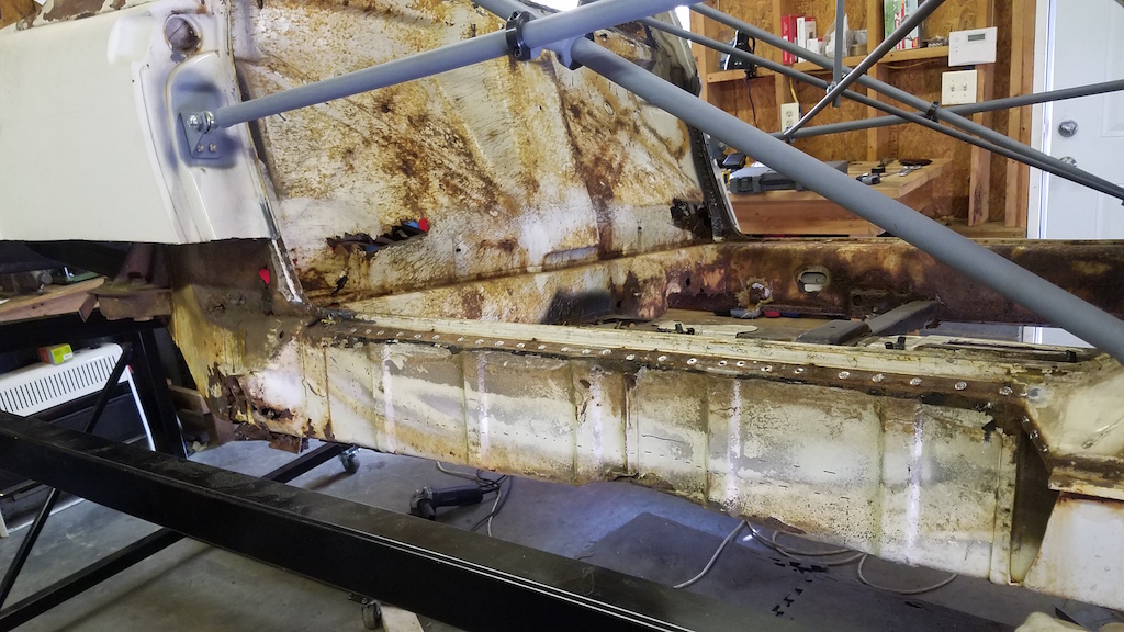 I didn't cut the entire long off so that I had a reference point for the new panels. It's going to mean lots of welding. Warpage is something I'm concerned about. 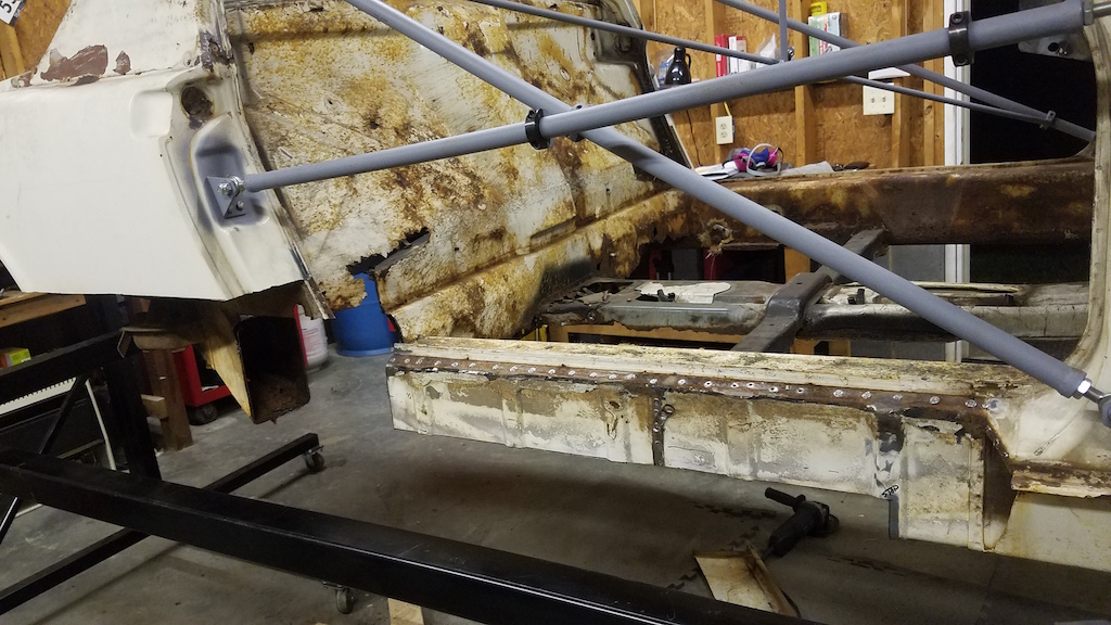 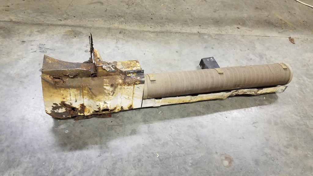 Looking from the inside: 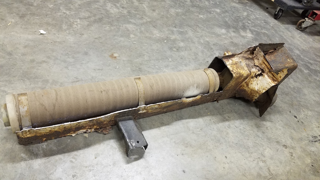 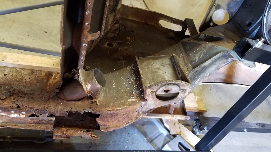 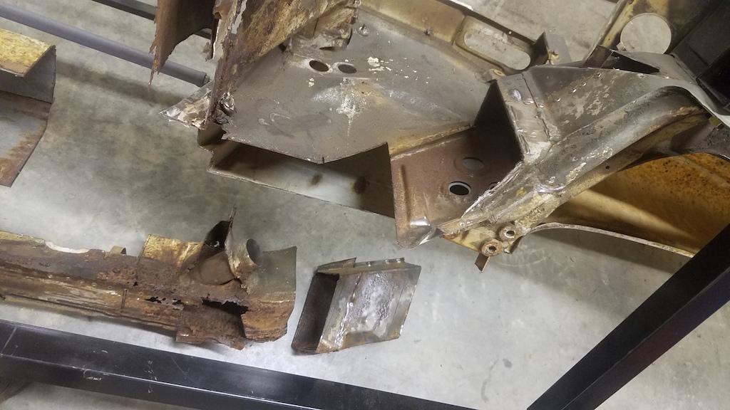 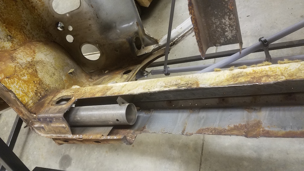 That last picture shows something interesting. There is an internal plate that is sandwiched between longitudinal panels. I'm betting that plate is there to help distribute the load into the long. Extending that plate the length of the long would probably improve chassis stiffness. I've got a new computer on the way that will handle Solidworks FEA so I will give a shot at testing some of my ideas prior to building it. That new computer will also handle Flow Sim stuff quite well and I've got some wild idea's to try out.. |
|
|
|
| 914forme |
Aug 25 2019, 08:37 AM
Post
#48
|
|
Times a wastin', get wrenchin'! Group: Members Posts: 3,896 Joined: 24-July 04 From: Dayton, Ohio Member No.: 2,388 Region Association: None |
If you are not going to use the heater duct for anything take it out, and run a piece front to back up the log as far as you can, out of 16 ro 14 ga. You can get it plasma cut for easy fitment. Makes part of the engmann kit with additional support all the way back.
This is open the inside (cabin side) up to the -4 mount. If you where using a bulk head mount, I would go all the way up the inside to the console. Great progress way to jump in there, and get it done right! Match that with the 914ltd kit, on the outside all new metal. That chassis would be strong. Picture worth a thousand words here. Red is the new piece take all the way up the inner log in to the cabin - to the front. Black ex is the heater tube too be removed. If you are using them for cooling lines or something else, just use an elbow and come out straight in the flat section of the log. 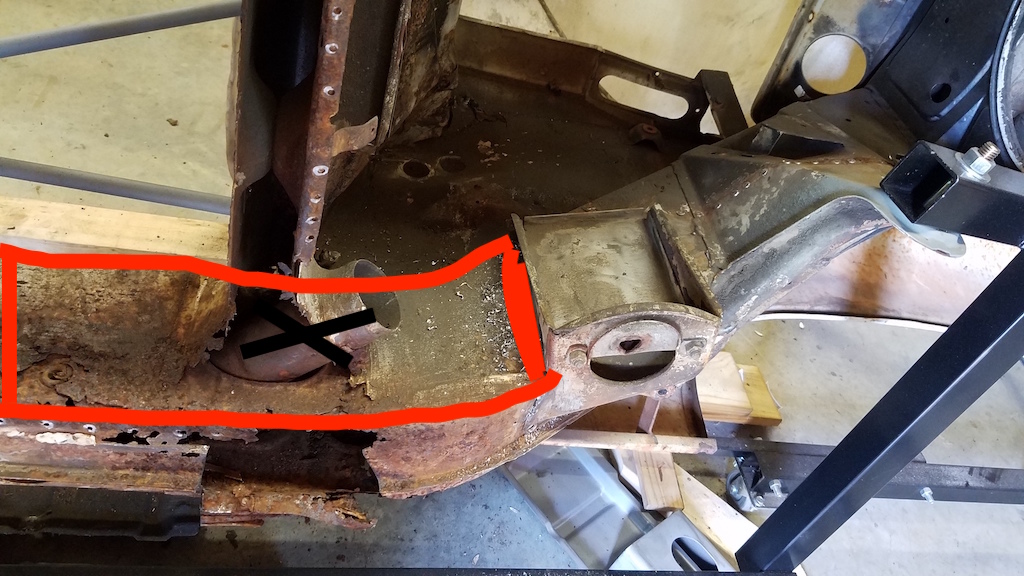 |
|
|
|
| 914forme |
Aug 25 2019, 08:48 AM
Post
#49
|
|
Times a wastin', get wrenchin'! Group: Members Posts: 3,896 Joined: 24-July 04 From: Dayton, Ohio Member No.: 2,388 Region Association: None |
Of course you come this far, Tangerine makes a nice kit that while your fender is off would help stiffest the consoles both inner and outer side.
Inner Console Reinforcements ,and Rear Pickup PointsReinforcing Kit. Both excellent products like all of Chris' stuff is |
|
|
|
| Joemo5 |
Sep 15 2019, 10:25 PM
Post
#50
|
|
Member Group: Members Posts: 54 Joined: 1-April 18 From: Charlotte, North Carolina Member No.: 22,011 Region Association: South East States |
@914forme Thanks for the suggestions! I will likely experiment with various versions of stiffening with the new computer and stress analysis (FEA). It will likely be over engineered but it makes me happy. (IMG:style_emoticons/default/piratenanner.gif) Still waiting on the computer to come in.. Lenovo needs to get their act together.
Since the rust extends all the way back to the suspension console and I'm working in the area, I started looking into the raised suspension console option. After some research on the 914 simi trailing arms, I can't convince myself that's the way to go. So.. I'm looking into a 996 suspension swap. The rear has a multi-link setup that looks promising. I'm picking up Boxster front suspension components tomorrow from the junk yard. Basically whats in the following pic, except for the struts and rack/pinion (IMG:style_emoticons/default/idea.gif) 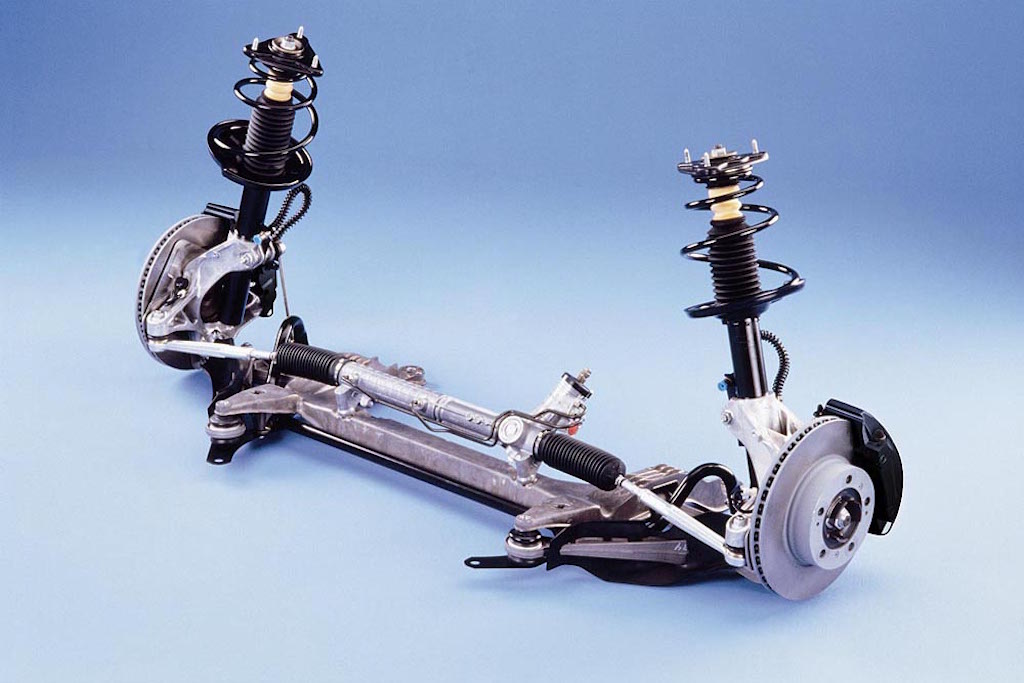 Lots of head scratching ahead of me. Bought some of the best suspension books known to man and will use Optimum K suspension software. 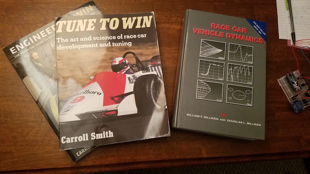 http://www.optimumg.com/software/optimumkinematics/ |
|
|
|
| Chris914n6 |
Sep 16 2019, 12:19 AM
Post
#51
|
|
Jackstands are my life. Group: Members Posts: 3,492 Joined: 14-March 03 From: Las Vegas, NV Member No.: 431 Region Association: Southwest Region |
Kool project.
Just wanted to touch base with a few things.... Your board mentions Stand alone ECU, it will need to be able to run Direct Injection. DI injectors are individually tested for flow and resistance and marked. These 2 numbers will need to be entered into the ECU to get the fueling accurate. Variable output pumps have been around since the 90s. Back then it was 2 stage, normal driving and reduced voltage for quietness at idle. DI has been around in German cars for a decade, but they used normal feed pumps with a pressure regulator built into the assembly to feed a mechanical HP pump. Thus, I think the tightness of PWM is solely for emissions requirements and you should be able to do without as long as it's near the factory specs. The Stand alone can be programmed as needed. |
|
|
|
| jd74914 |
Sep 16 2019, 05:21 AM
Post
#52
|
|
Its alive Group: Members Posts: 4,852 Joined: 16-February 04 From: CT Member No.: 1,659 Region Association: North East States |
Why OptimumK? Not sure how different the prices are, but if you can get your hands on a copy of Lotus Shark I would definitely recommend going that route. OK isn't super computationally stable (at least the versions that I've used) and sometimes give some really wacky outputs. Just something to watch out for.
I'd also recommend picking up Gilespie's vehicle dynamics book. I've found it to be a bit more feasible than RCVD and it goes into some stuff very applicable to passenger vehicles like suspension loading due to angled axles, etc. which RCVD misses. |
|
|
|
| 914forme |
Sep 16 2019, 06:10 AM
Post
#53
|
|
Times a wastin', get wrenchin'! Group: Members Posts: 3,896 Joined: 24-July 04 From: Dayton, Ohio Member No.: 2,388 Region Association: None |
(IMG:style_emoticons/default/lol-2.gif) Lenovo needs to get their act together (IMG:style_emoticons/default/agree.gif) 100%.
We are now a Dell shop, orders come in on time, I have a dedicated rep, not a rep to my rep. End of October I am going to the Dell logistic center in Nashville to get the final details on our roll out plans done. Zero touch system configuration, we will just hand all new hires and new students a shrink wrapped laptop. Just like you get at the box stores. We touch it for no reason, except for DOA, very small number - normally due to the shipping company running a fork lift thru it. (IMG:style_emoticons/default/wacko.gif) Our Dell service rates are at 0.33% across the entire fleet. We are a school, so that number is very low. Our Lenovo fleet was much higher repair rate. One year we had a failure rate of 33% - which meets Critical Situation Levels, nothing from Lenovo for the fix. We ended up fixing them with SSDs retrofitted. Following model from Lenovo only came with SSD or M2 Flash. We are a Lenovo repair center so, we got the money for all the hard drives we replaced. I had boxes of drives in our warehouse waiting to be chipped. This year we ordered Lenovo Tiny - All - In - Ones, shipments have been back ordered so many times, promised ship dates revised three times now. And they are supposed to be here today, we will see, not holding my breath. We have watched a steady decline in Lenovo over the last 4-5 years. YMMV Neat project, love the idea of Boxster / 996 suspension. In reality I would go double wishbones up front if I was changing the entire thing out, and spending the time to do all the engineering. But then if using the trailing arms out back it is still a compromise. |
|
|
|
| Joemo5 |
Sep 16 2019, 08:15 PM
Post
#54
|
|
Member Group: Members Posts: 54 Joined: 1-April 18 From: Charlotte, North Carolina Member No.: 22,011 Region Association: South East States |
@Chris914n6 I'm hoping that by the time I get to setting up the fuel system, Gen V LT chevy swaps are as popular as the LS swaps and there will be lots of info out there on topic if there isn't already. i'm not there yet but you guys are probably right, the PWM fuel pump won't be that hard to get figured out.
@jd74914 I'd like to use Optimum K because I have experience with it and know that when working with it to design the SAE Baja car, we barely scratched the surface of what's available. The only downfall is that the free version only lasts 2 weeks and a yearly subscription is like $700. I haven't heard of Lotus Shark but will look into it. Thanks for the Gillespie recommendation. @914forme I've had a Lenovo at work for the past 5 years with only one hiccup with a graphics card. Swapped it out for a Quadro P4000 and problem solved. So when looking for computer's I naturally leaned towards what I'm used to. Lenovo also seamed to have the best pricing/spec. I didn't look around too much though.. I did almost choke when I looked up what those BOXX computer's cost. (IMG:style_emoticons/default/WTF.gif) Ended up with a P320 with an i9-9900, 512g SSD, 16GB DDR4 RAM, and an RTX4000. Should blaze through simulations and run Solidworks with ease (IMG:style_emoticons/default/aktion035.gif) Double A-arm? I like the sounds of that (IMG:style_emoticons/default/biggrin.gif) |
|
|
|
| Joemo5 |
Sep 16 2019, 09:54 PM
Post
#55
|
|
Member Group: Members Posts: 54 Joined: 1-April 18 From: Charlotte, North Carolina Member No.: 22,011 Region Association: South East States |
Pics of the afore mentioned boxster suspension that I brought home today (IMG:style_emoticons/default/piratenanner.gif)
   Heres the current idea: Use all of what's pictured but instead of a macpherson strut, convert it to a double A-arm suspension. The top mount for the strut is nothing but a clamping diameter. Fabrication wise, it shouldn't be too hard create an upper ball joint mount out of a chunk of aluminum that fits into that clamping diameter. Extending said chunk of aluminum out the bottom of the clamping diameter should allow attachment of a steering arm that sticks out rearwards and allows the use of the 914 steering rack. Maybe a little far fetched but i think it's feasible. Since I have both the 914 and boxster suspension sitting in my garage, I weighted them both to get a comparison. I used a bathroom scale so these aren't all that accurate. 914 Suspension including: cross member, control arms, torsion bars, struts, rotors, calipers, hubs, and sway bar 113 lbs Boxster Suspension including: Everything listed above EXCEPT struts 98lbs The boxster rotors are really heavy.. like 16.5 lbs heavy. While we're on this suspension topic.. here's my current plan for the rear suspension. I would like to swap in a suspension that will play well with the front suspension that I have chosen. The boxster, cayman and 996 all have front suspensions that are very similar. The 996 however, has a multilink rear suspension that looks like it would fit very well into the rear of a 914. Here's a google pic for reference: 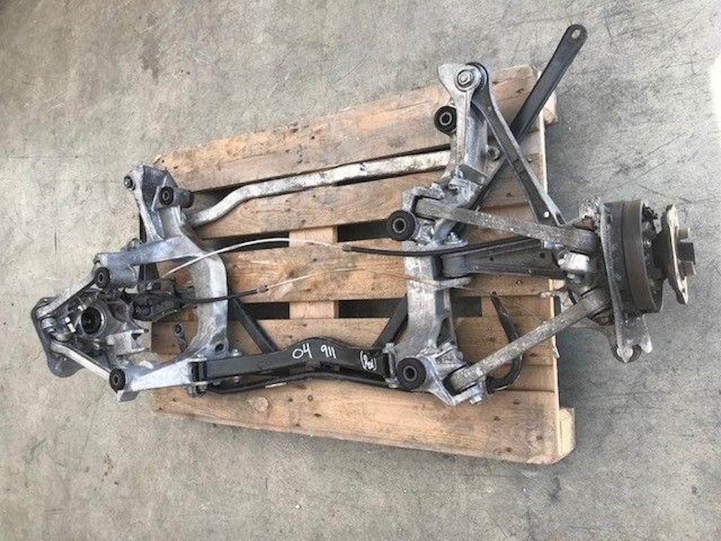 Use your imagination here.. take the above components, build a rear subframe that houses the engine and transmission. Wouldn't look identical but heres another picture for reference. 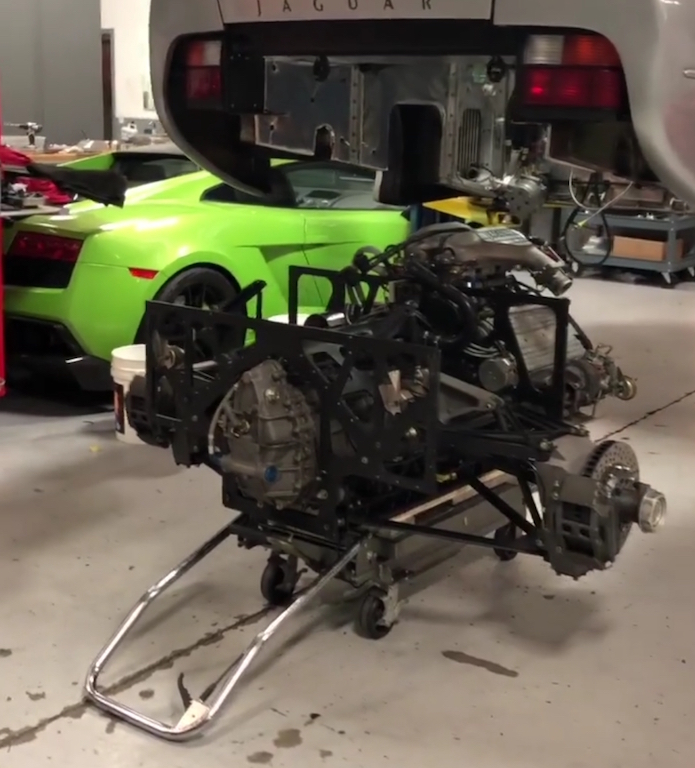 I'm definitely headed down a path of unknowns. it will be hard to put my thumbs on exactly what modifications need to be done before taking accurate measurements and putting it in optimum K. Ideally the rear would be a direct swap in and then alter the front double A-arm's until there's an acceptable roll axis and camber curves. The 996 rear suspension is likely catered for the rear engine and higher polar moment of inertia so there's that to deal with.. Why do I want to go down this path? - My boxster S calipers are a direct fit to the boxster knuckles and should be to the 996 knuckles - No compromised trailing arm geometry - 4 corner wheel speed sensors (lots of options: ABS, traction control, etc) - An off the shelf axle may work with my G86.20 trans: more research needed - Off the shelf boxster/996 rotors and pads - Use of this: https://www.jrishocks.com/shop/specialty/hy...ic-ride-height/ |
|
|
|
| dakotaewing |
Sep 16 2019, 09:55 PM
Post
#56
|
|
Senior Member Group: Members Posts: 1,163 Joined: 8-July 03 From: DeSoto, Tx Member No.: 897 Region Association: Southwest Region |
Great project! I'm kind of in a similar spot in my project, but it has been that way for years.
My only suggestion looking at your chassis would be to go ahead and get it soda blasted, and epoxy primer'd now. It will expose anything hidden that you might not see other wise, and will also save you the time of mechanically removing paint otherwise. |
|
|
|
| Joemo5 |
Oct 5 2019, 07:39 PM
Post
#57
|
|
Member Group: Members Posts: 54 Joined: 1-April 18 From: Charlotte, North Carolina Member No.: 22,011 Region Association: South East States |
QUOTE(dakotaewing @ Sep 16 2019, 11:55 PM) Great project! I'm kind of in a similar spot in my project, but it has been that way for years. My only suggestion looking at your chassis would be to go ahead and get it soda blasted, and epoxy primer'd now. It will expose anything hidden that you might not see other wise, and will also save you the time of mechanically removing paint otherwise. Yeahh, I would like to get it blasted. However every different option seams to have it's draw backs. Soda has to be neutralized, sand stays in cracks forever, dips remove paint in between pinch welds.. I haven't decided yet. My plan is to fix to replace the worst sections, then move on to the smaller rust issues, including blasting. |
|
|
|
| mepstein |
Oct 5 2019, 07:51 PM
Post
#58
|
|
914-6 GT in waiting Group: Members Posts: 19,970 Joined: 19-September 09 From: Landenberg, PA/Wilmington, DE Member No.: 10,825 Region Association: MidAtlantic Region |
Plastic bead blasting with garnet on the rusty spots.
|
|
|
|
| Joemo5 |
Oct 5 2019, 09:24 PM
Post
#59
|
|
Member Group: Members Posts: 54 Joined: 1-April 18 From: Charlotte, North Carolina Member No.: 22,011 Region Association: South East States |
So I've been having some fun. I started breaking down the boxster suspension. Here's a pic pressing out the bearing. Those things were in there!
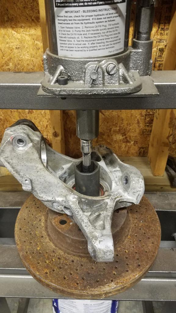 I was going to start attempting to model some of the important points in Solidworks and then remembered reading an article about photogrammetry and how it's possible to obtain 3D data from pictures. So I gave it a whirl and I am freaking mind blown. I used my samsung S7 camera (cell phone) on the auto settings and a really basic setup to suspend the knuckle from strings. Here's the physical setup. 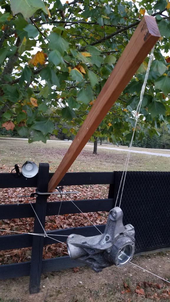 I took 219 picture at a multitude of angles. I did no editing of the pictures and uploaded them into RealityCapture. A few clicks later, about 10 minutes of processing time and NO cleanup this is what it generated. 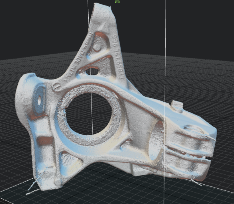 Here's a video flipping the mesh around https://www.youtube.com/watch?v=SJXa_tz24t4 i am beyond stoked! (IMG:style_emoticons/default/piratenanner.gif) This is more than good enough to cleanup and retain a reasonable accuracy for modeling purposes. I'm still learning how to cleanup the mesh and manage the file size. However, this took maybe 4 hours, including learning everything for the first time. I could likely repeat this process in less than an hour for a new part. The idea here is that this will vastly speed up my process to design a custom front dual A-arm suspension. What a time to be alive.. |
|
|
|
| Joemo5 |
Oct 7 2019, 08:22 PM
Post
#60
|
|
Member Group: Members Posts: 54 Joined: 1-April 18 From: Charlotte, North Carolina Member No.: 22,011 Region Association: South East States |
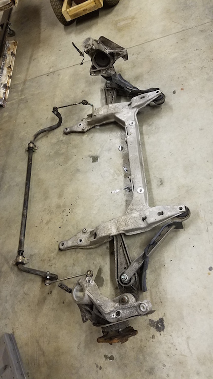
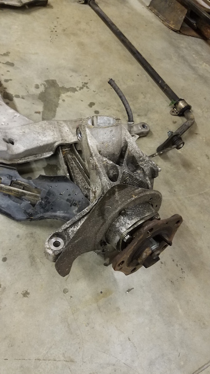
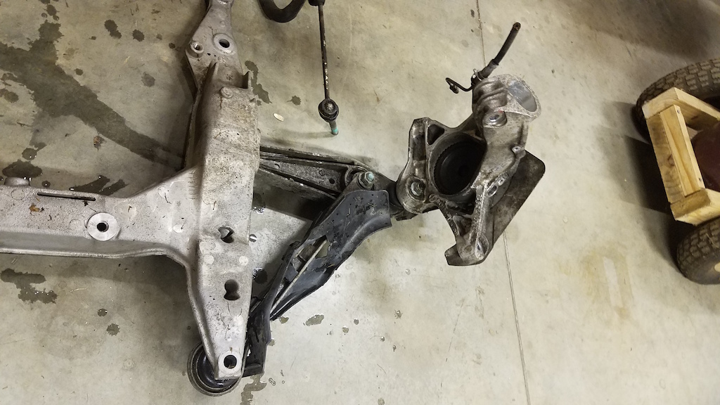
Dad and I drove to Tennessee yesterday and picked up the rear suspension out of a 996 C2. Made for about 12 hours of driving in one day but it was a killer deal. Here's what we brought home.
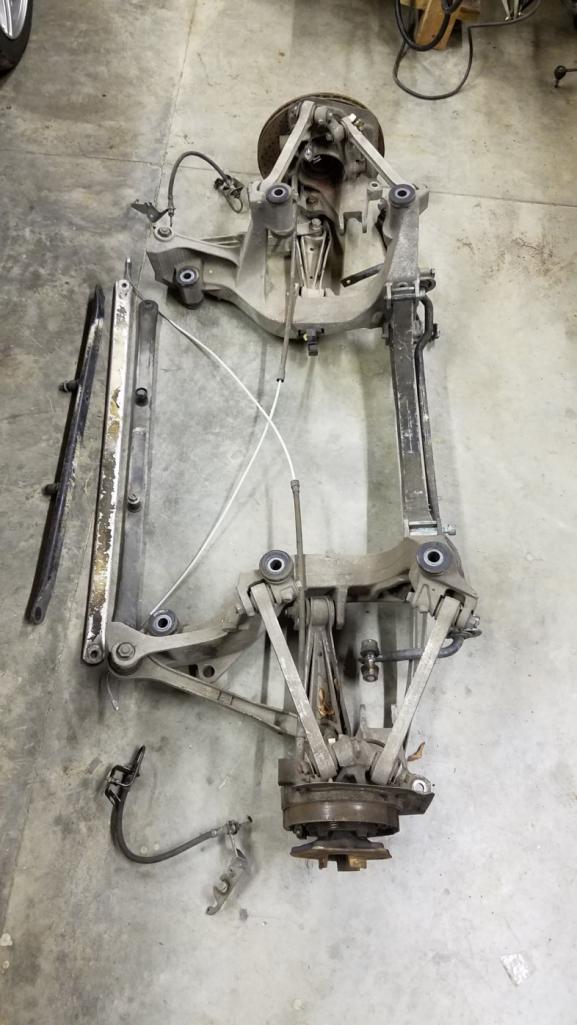 I took a few pictures of the mounting points on the 996 and was pondering the best way to mount it to the 914. The 996 has studs that stick down. I'm thinking the mounting points will be inboard of the 914 frame rails. 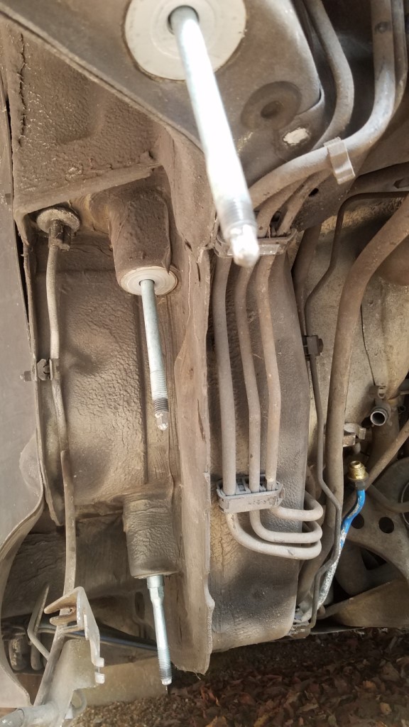 Along the same lines, I tossed the Boxster K-member on the bottom of the car to get an idea of where the mounting points fell. 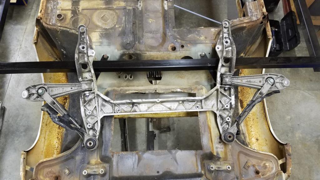 |
|
|
|
|
1 User(s) are reading this topic (1 Guests and 0 Anonymous Users)
0 Members:

|
Lo-Fi Version | Time is now: 15th July 2025 - 04:31 AM |
Invision Power Board
v9.1.4 © 2025 IPS, Inc.