|
|
|
Porsche, and the Porsche crest are registered trademarks of Dr. Ing. h.c. F. Porsche AG.
This site is not affiliated with Porsche in any way. Its only purpose is to provide an online forum for car enthusiasts. All other trademarks are property of their respective owners. |
|
|

  |

| Montreal914 |
 May 27 2018, 03:35 PM May 27 2018, 03:35 PM
Post
#1
|
|
Senior Member  Group: Members Posts: 1,543 Joined: 8-August 10 From: Claremont, CA Member No.: 12,023 Region Association: Southern California |
When I first saw the JWest shift linkage upgrade (NLA), I though it was a very elegant way to handle the support of the ball sleeve mechanism in the side shift gearbox console. I assume cost was the reason Porsche didn't do it that way.
I've always wanted to do something similar (IMG:style_emoticons/default/stirthepot.gif) . Being on a budget, I decided to modify/fabricated all of the components myself but pretty much all of this upgrade can be done with parts available through our member vendors here in one form or another. Here we go! (IMG:style_emoticons/default/sawzall-smiley.gif) (IMG:style_emoticons/default/smash.gif) (IMG:style_emoticons/default/welder.gif) (IMG:style_emoticons/default/driving.gif) Shift Console Preparation All of this started when I got a spare gearbox with a broken shift console. I though this was the perfect candidate to play with since it can't be used in its current form. I cut the remaining part of the bushing tab and file the casting flush. 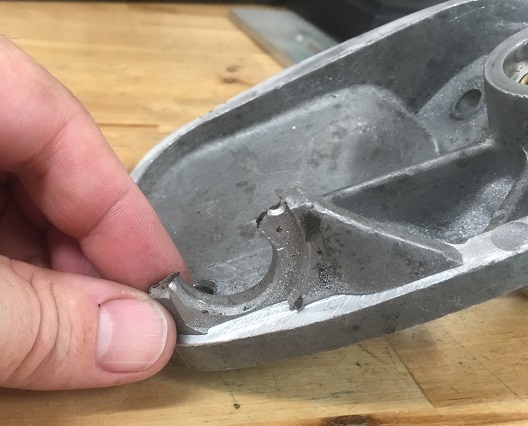 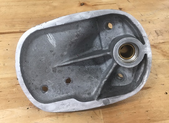 Then I prepared what would be the two new supporting tabs in which there would be oil impregnated bronze bushings. These tabs are made from a 1 1/4" x 3/8" aluminum flat bar. The 7/8" hole was machined in the right location (center 15mm from the console reference surface) to maintain the stock position of the shift rod. 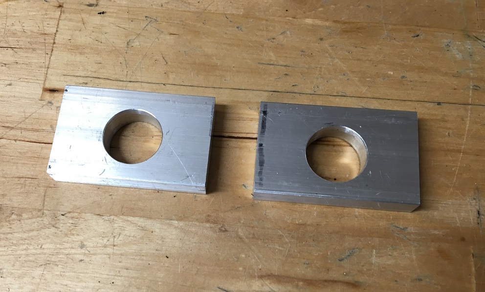 The bronze bushings (McMaster Carr 6338K426) were grooved to accept a snap ring (McMaster Carr 98585A115) to secure them to the tabs. 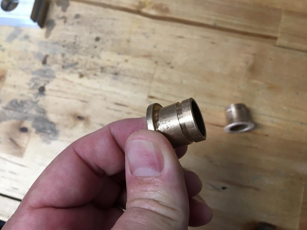 Using a piece of 5/8" shaft, I do the first layout of the assembly. 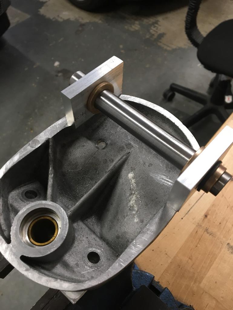 Then, with a file (aluminum is a beautiful material), I did the weld preparation of the various surfaces as per recommendations from my welder. 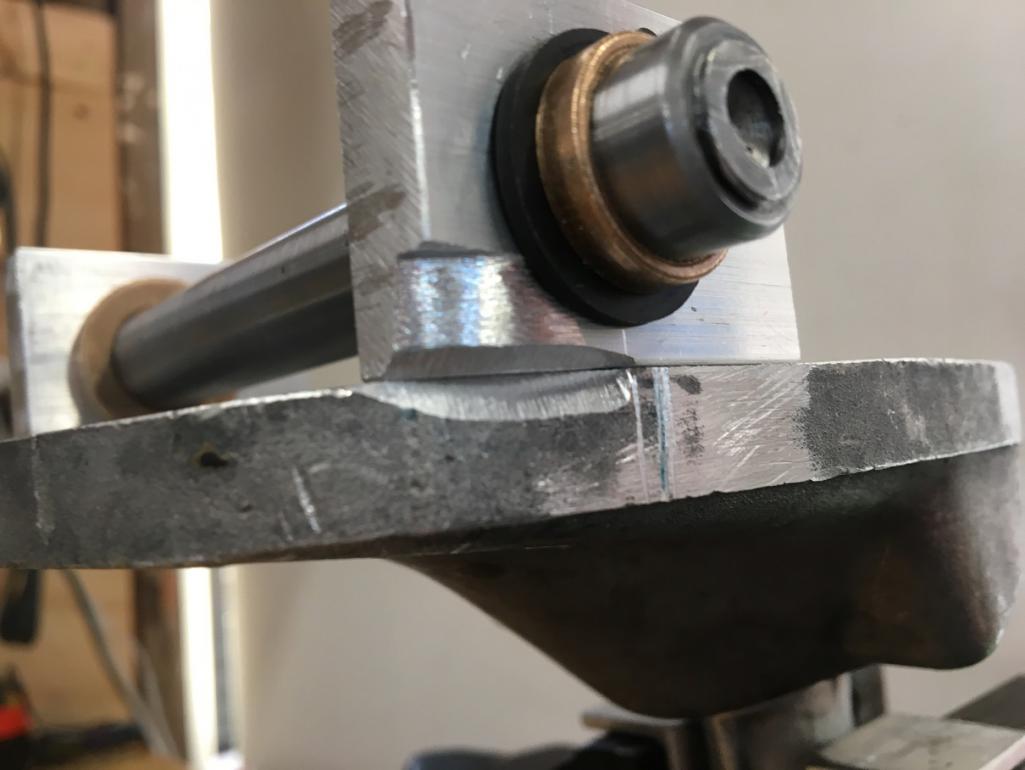 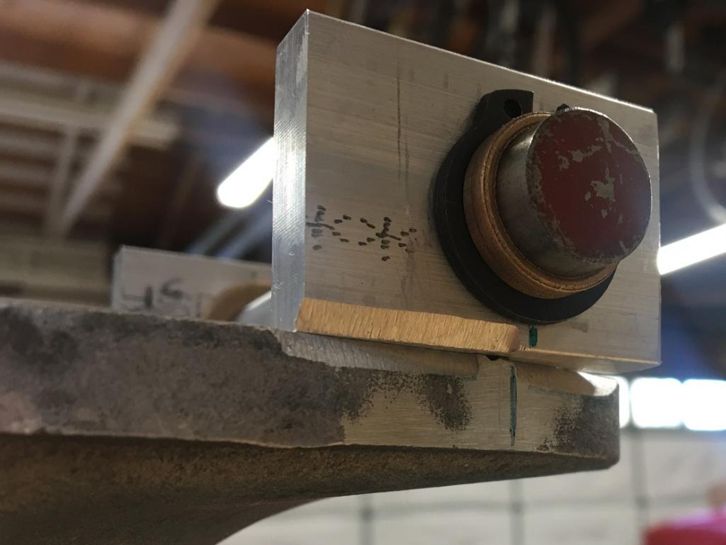 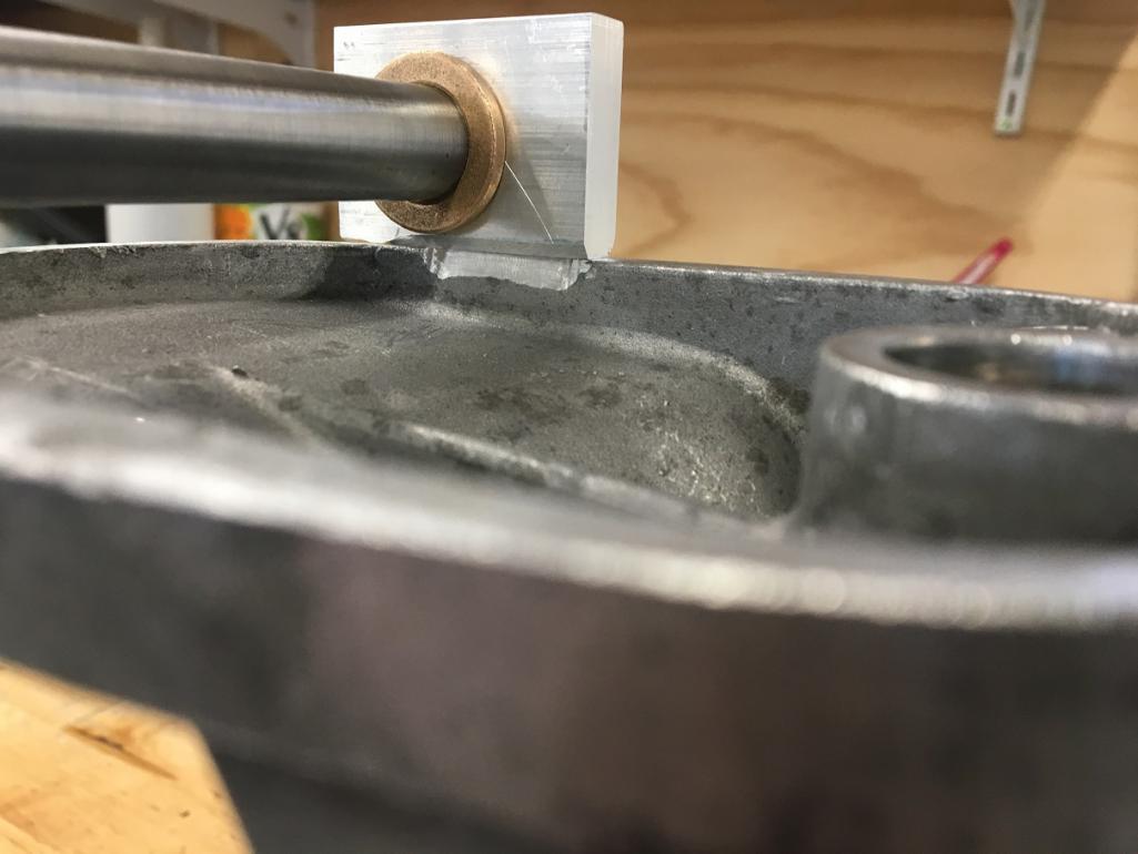 Then my welder did his magic while taking his time and extra care to make sure the material didn't pull which would have resulted with bent tabs where bushings wouldn't have lined up and ruined the whole thing. Yes the preferred way of doing this would have been to weld first and machine after but that would have made the machining of the tabs more expensive due to an elaborate setup to hold the console. I would probably do it this way if I was doing it again, but since I had a good welder, he pulled it off nicely (IMG:style_emoticons/default/sunglasses.gif) 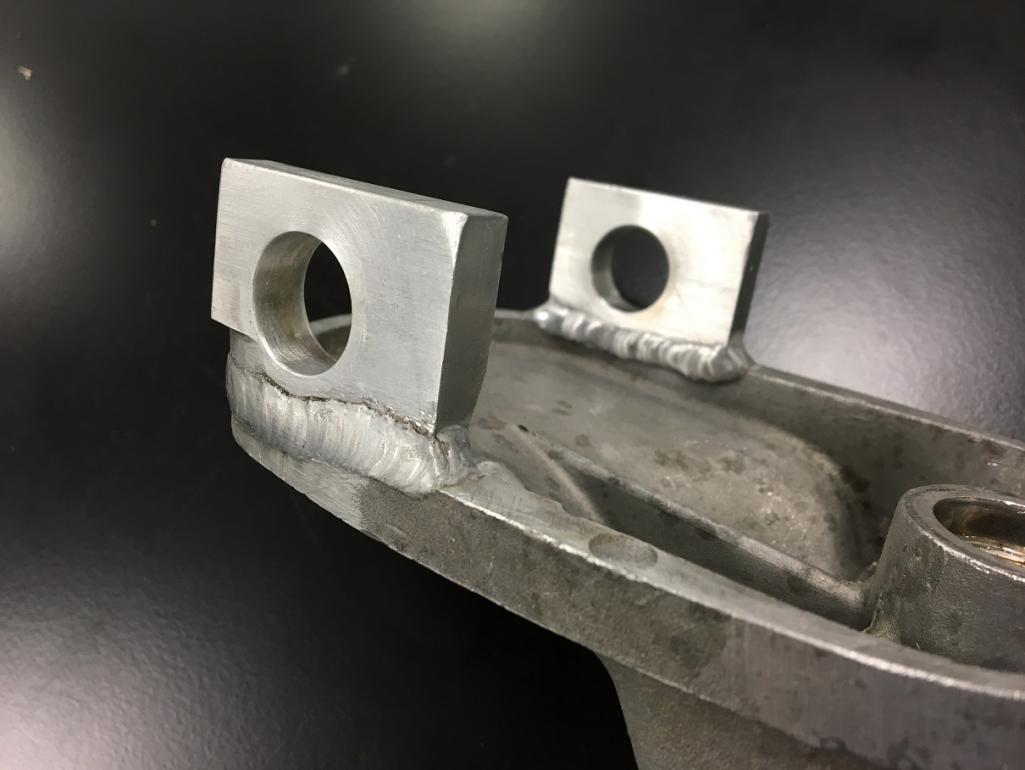 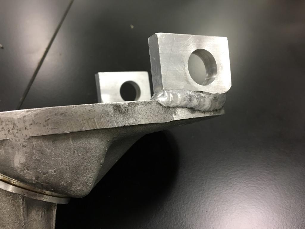 Then I used my trusted hack saw and files to smooth it out and bring it to a shape that could ressemble somewhat a stock casting form. (IMG:style_emoticons/default/w00t.gif) 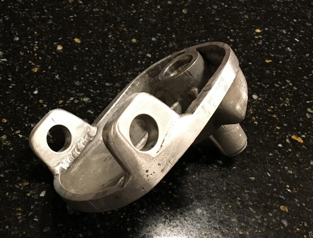 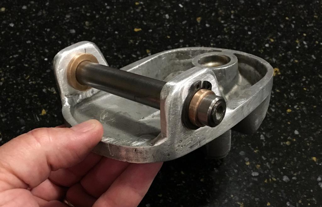 Last, I reassembled the rest of the components with a fresh seal and the console assembly was ready to be installed on the gearbox. (IMG:style_emoticons/default/beer3.gif) 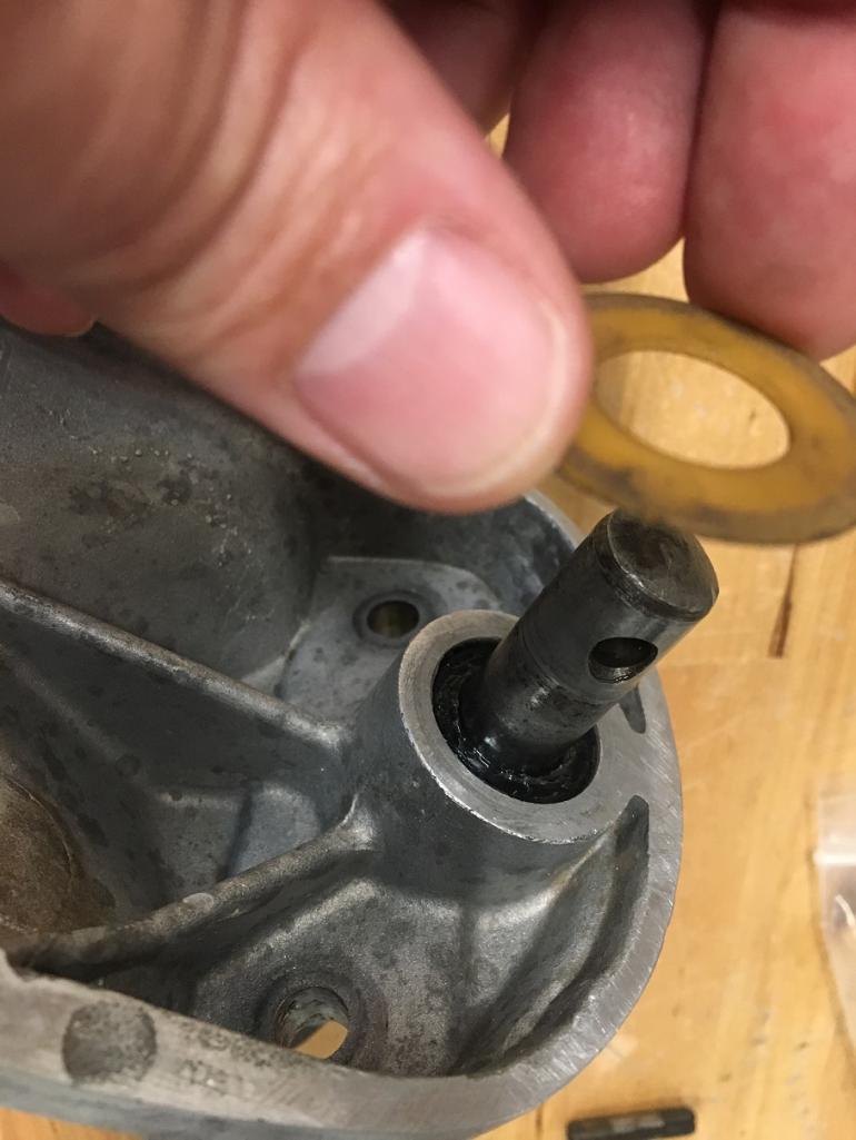 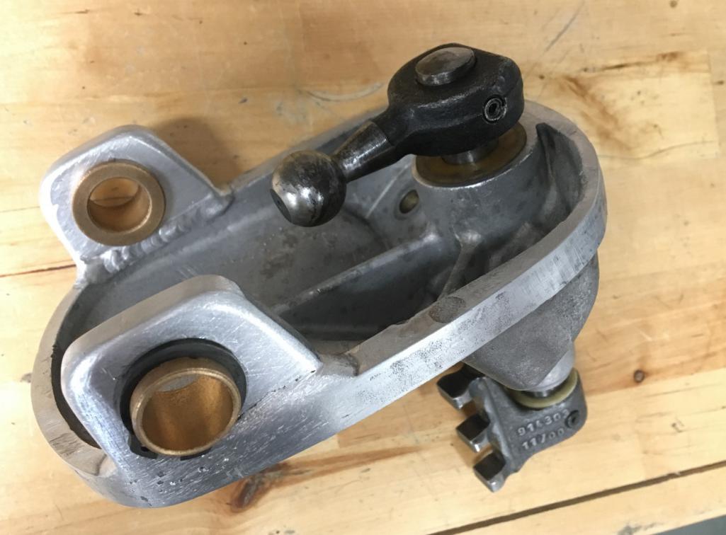 |
   |

 
|
| Montreal914 |
May 27 2018, 03:54 PM
Post
#2
|
|
Senior Member Group: Members Posts: 1,543 Joined: 8-August 10 From: Claremont, CA Member No.: 12,023 Region Association: Southern California |
Next step was to start working on the front rod of the shift linkage, the one hidden in the tunnel.
My plan was to use two steering shaft U-joint which requires 4 spline stub shafts to connect to each side of both joint. So two joints and two shaft were needed for this project. Front shift Rod Modification The first thing I did was to take some measurement on the car to make sure I was keeping the same overall geometry. Then I drilled the four plug welds that are holding the rod end that connects to the stock joint by the firewall in the engine bay. 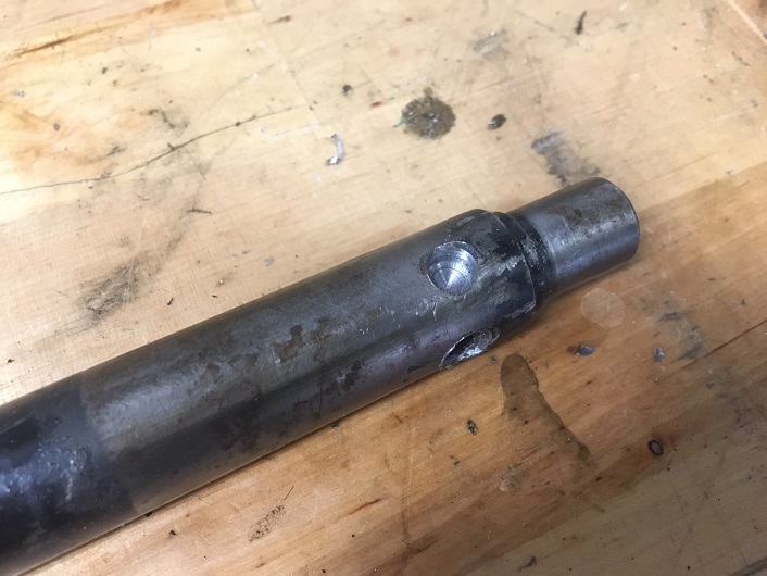 I ended up cutting the tube leaving four little tabs for the new rod end installation. 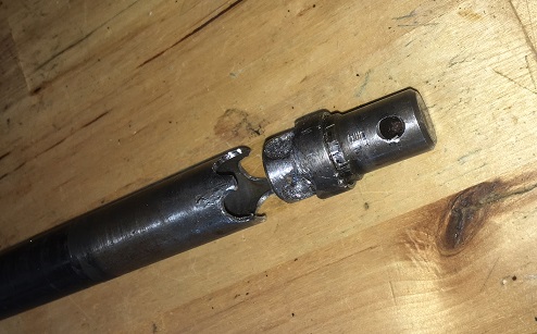 Then I cut the first steering shaft to get the splined end that would go at the end of the shift rod. 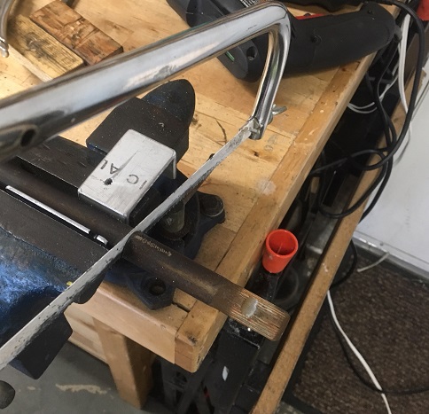 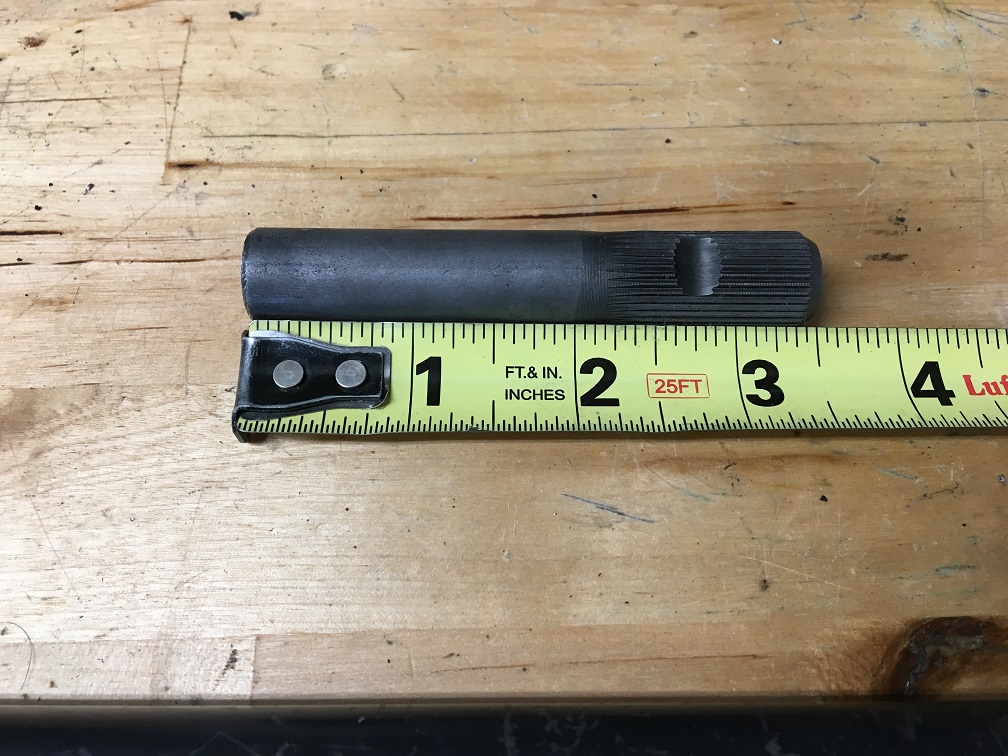 Measure twice for proper location. You can see where the four tabs were pinched a little to close the little gap between the tube ID and the steering shaft OD. 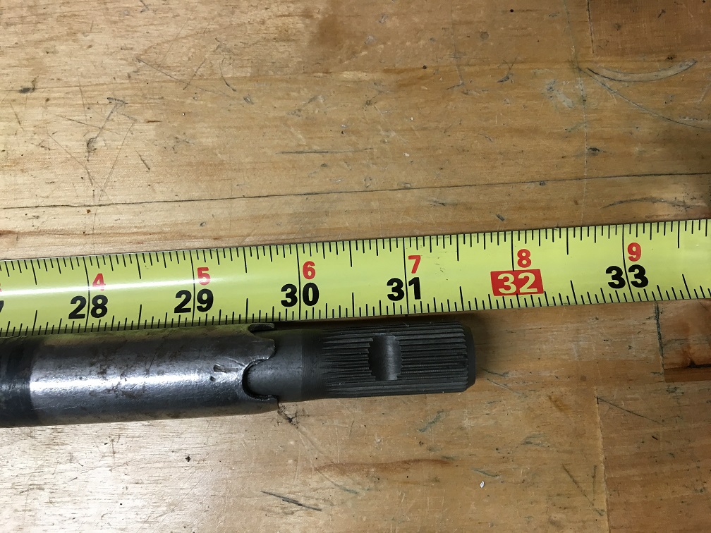 Welding... 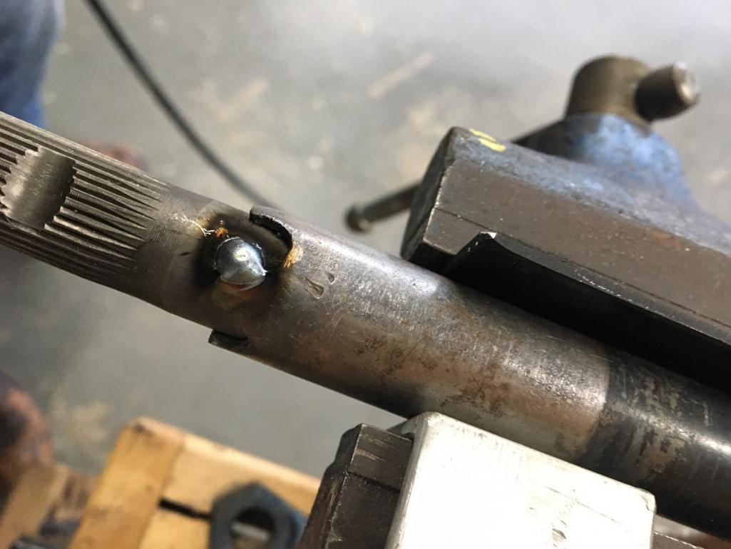 File the welds and sand smooth. Verification of the new 20mm firewall spherical bushing fit. That completes the preparation of the front shifter rod. (IMG:style_emoticons/default/beer3.gif) 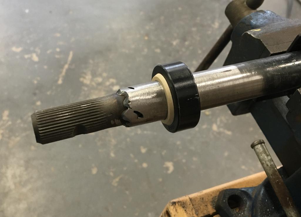 |
|
|
|
| Montreal914 |
May 27 2018, 04:06 PM
Post
#3
|
|
Senior Member Group: Members Posts: 1,543 Joined: 8-August 10 From: Claremont, CA Member No.: 12,023 Region Association: Southern California |
Firewall Bushing
I lucked out on this one as I had aluminum rings that I had designed in metric for another project and were left over. They happened to be a perfect match for the installation of the 20mm Igus spherical bushing. The only thing I needed was a thin spacer which I 3D printed at work. Done. The real thing can be purchased from Tangerine Racing, but since I already had parts, I just used them. 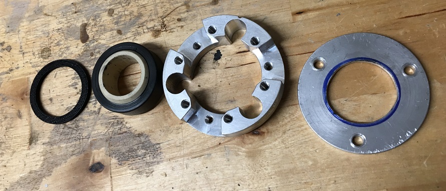 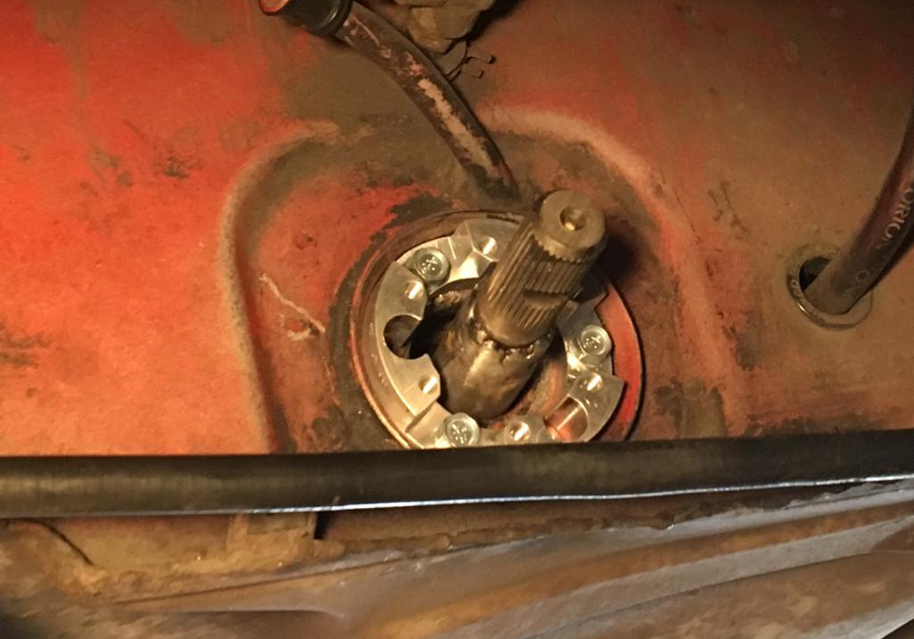 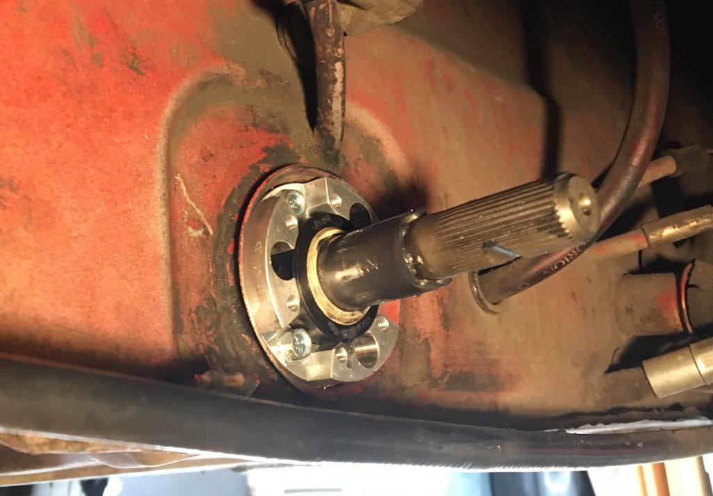 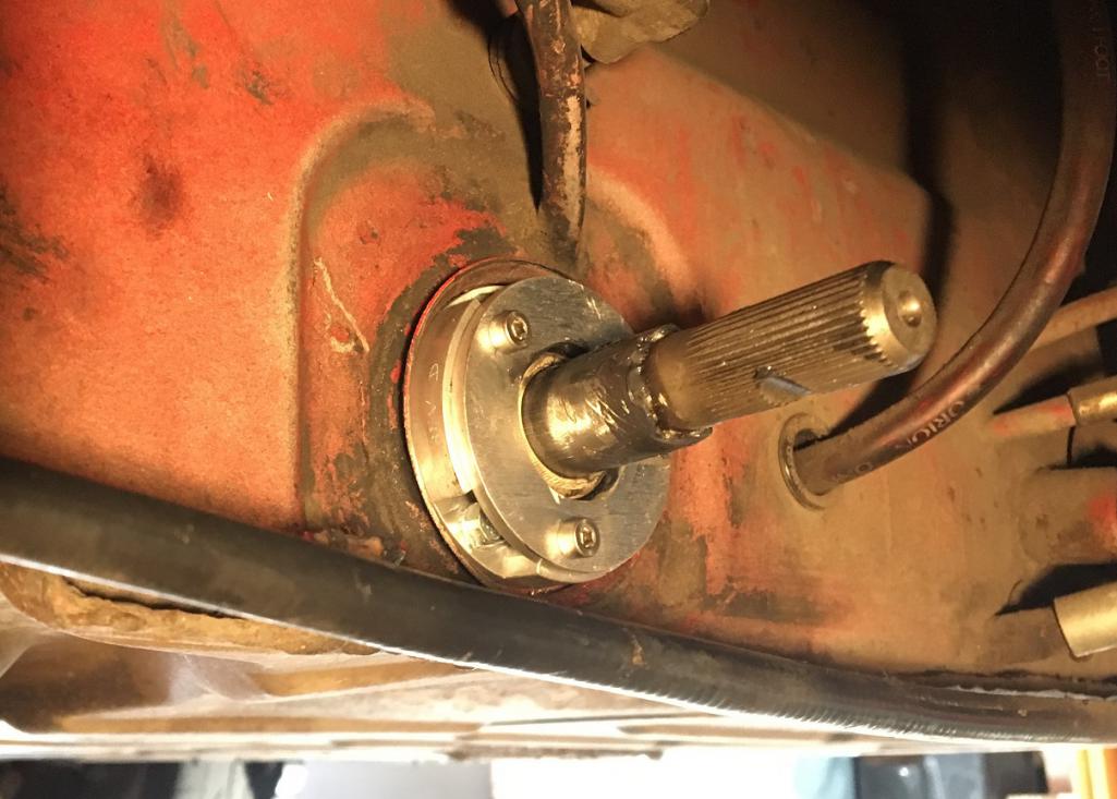 |
|
|
|
| Montreal914 |
May 27 2018, 04:21 PM
Post
#4
|
|
Senior Member Group: Members Posts: 1,543 Joined: 8-August 10 From: Claremont, CA Member No.: 12,023 Region Association: Southern California |
Shift Console Installation
Before installing the shift console onto the gearbox, I prepared the console shaft. The stock shaft is 15mm diameter. After thinking about the various parts and machining steps to be done, I had established that I would use the steering shaft as the shaft that would be in the console. The steering shaft is 16mm diameter, so the pivoting sleeve in the console had to be bored out from 15mm to 16mm which a nearby machine shop easily did for me. 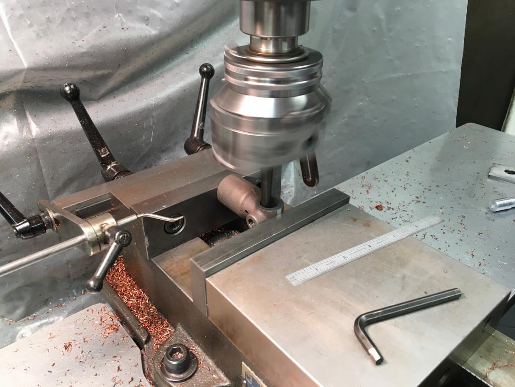 Then, the bronze bushings in the tabs were 5/8" diameter which is just under 16mm so a quick run on the lathe and they were matching with the shaft. The last thing left was the hole for the cone screw which was easily handled on the milling. Now the console is really completed and ready to be installed on the gearbox (provided it has been emptied from its oil...) 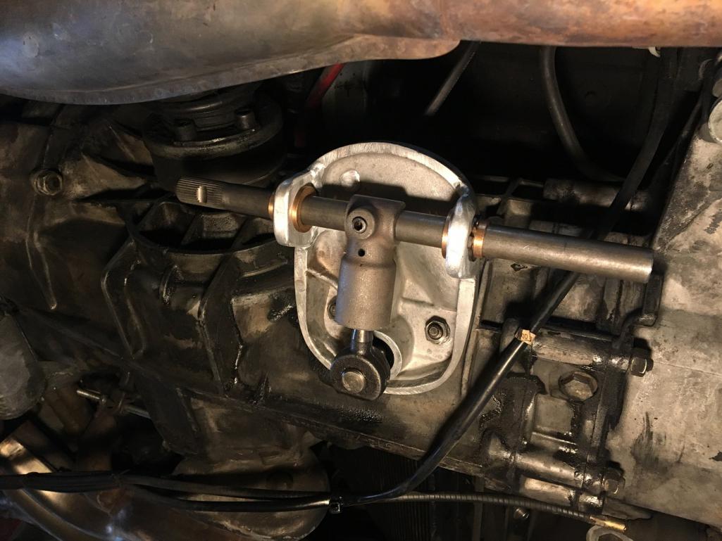 Console Cover For the cover, I used a couple of hole saws and made a hole for the rear end of the shaft, and another one to have access to the cone screw. With the rear bushing tab protruding a little, the cover fits tight and is locked so it doesn't need the strap anymore. 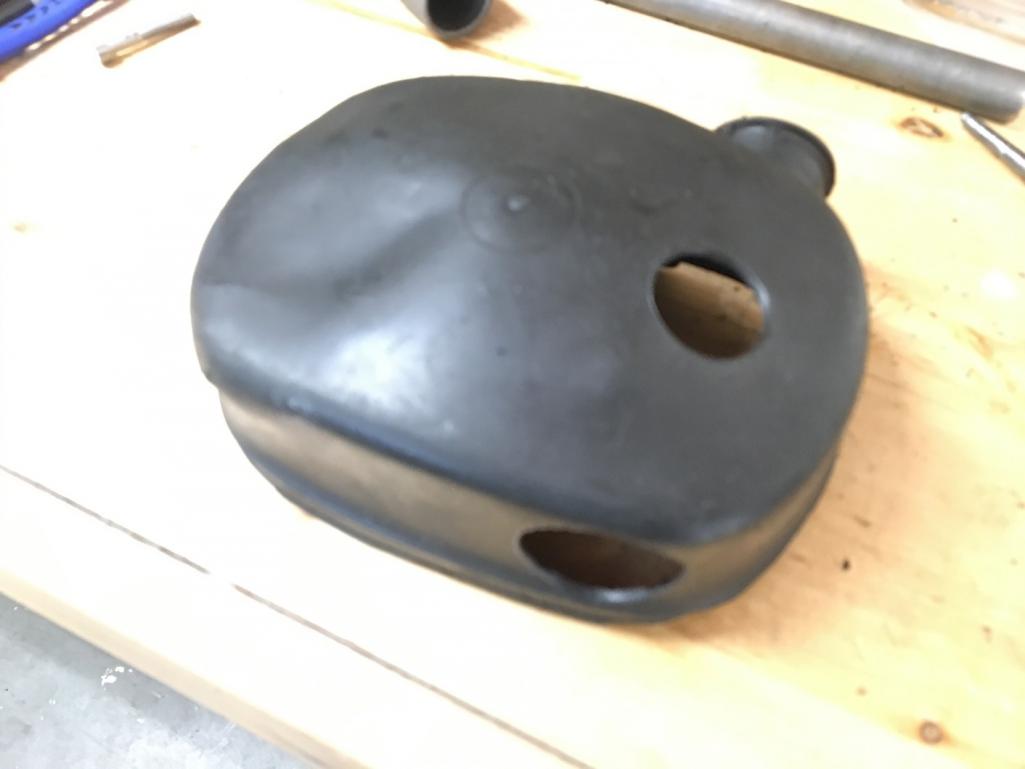 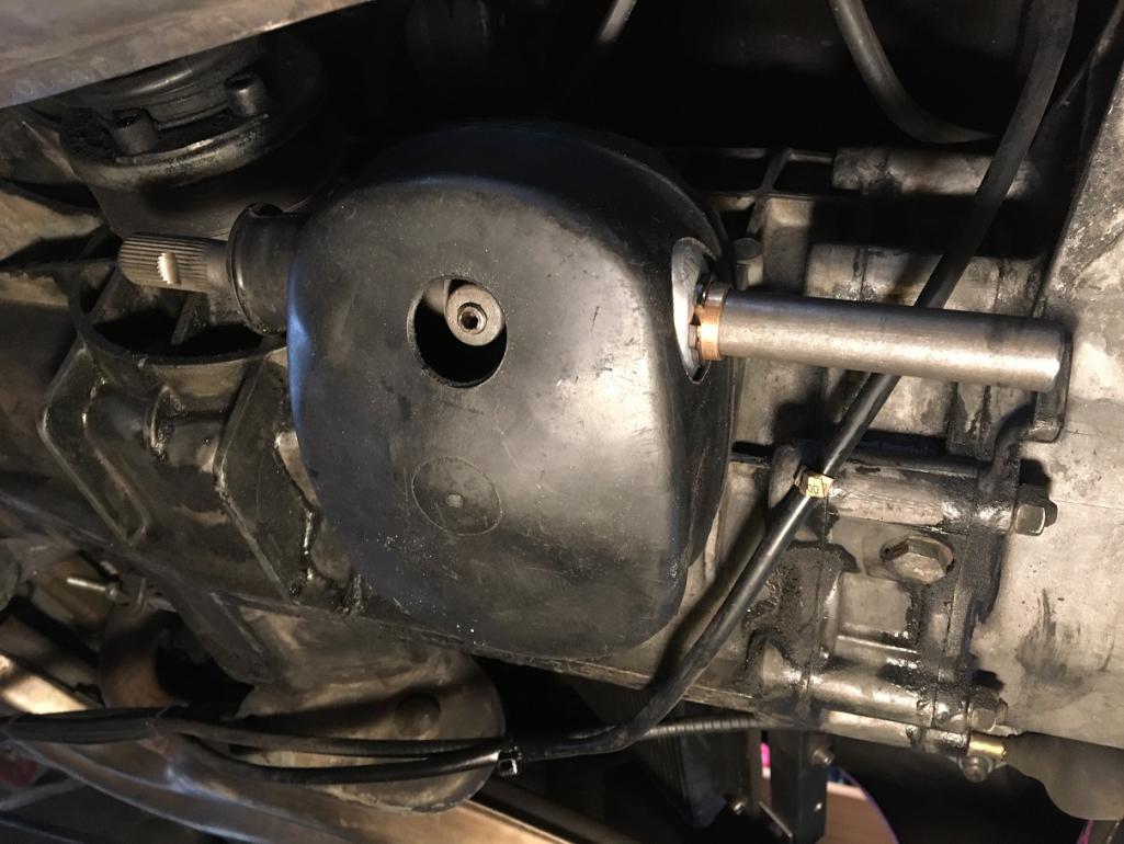 |
|
|
|
| porschetub |
May 27 2018, 04:26 PM
Post
#5
|
|
Advanced Member Group: Members Posts: 4,697 Joined: 25-July 15 From: New Zealand Member No.: 18,995 Region Association: None |
[quote name='Montreal914' date='May 28 2018, 09:35 AM' post='2613230']
When I first saw the JWest shift linkage upgrade (NLA), I though it was a very elegant way to handle the support of the ball sleeve mechanism in the side shift gearbox console. I assume cost was the reason Porsche didn't do it that way. I've always wanted to do something similar (IMG:style_emoticons/default/stirthepot.gif) . Being on a budget, I decided to modify/fabricated all of the components myself but pretty much all of this upgrade can be done with parts available through our member vendors here in one form or another. Here we go! (IMG:style_emoticons/default/sawzall-smiley.gif) (IMG:style_emoticons/default/smash.gif) (IMG:style_emoticons/default/welder.gif) (IMG:style_emoticons/default/driving.gif) Shift Console Preparation All of this started when I got a spare gearbox with a broken shift console. I though this was the perfect candidate to play with since it can't be used in its current form. I cut the remaining part of the bushing tab and file the casting flush. Nice job,how did you work out the placement off the weld on tabs ?,when I did mine I found it was rather critical so you get full engagement of all gears. I placed uni-joints 1 @ the console and another near the firewall ,I purchased these from a buggy parts supply vender and choose non splined ones so I had the ease of fine adjustment,once setup I cut grooves in the shafts for the correct 8mm clamp bolts. 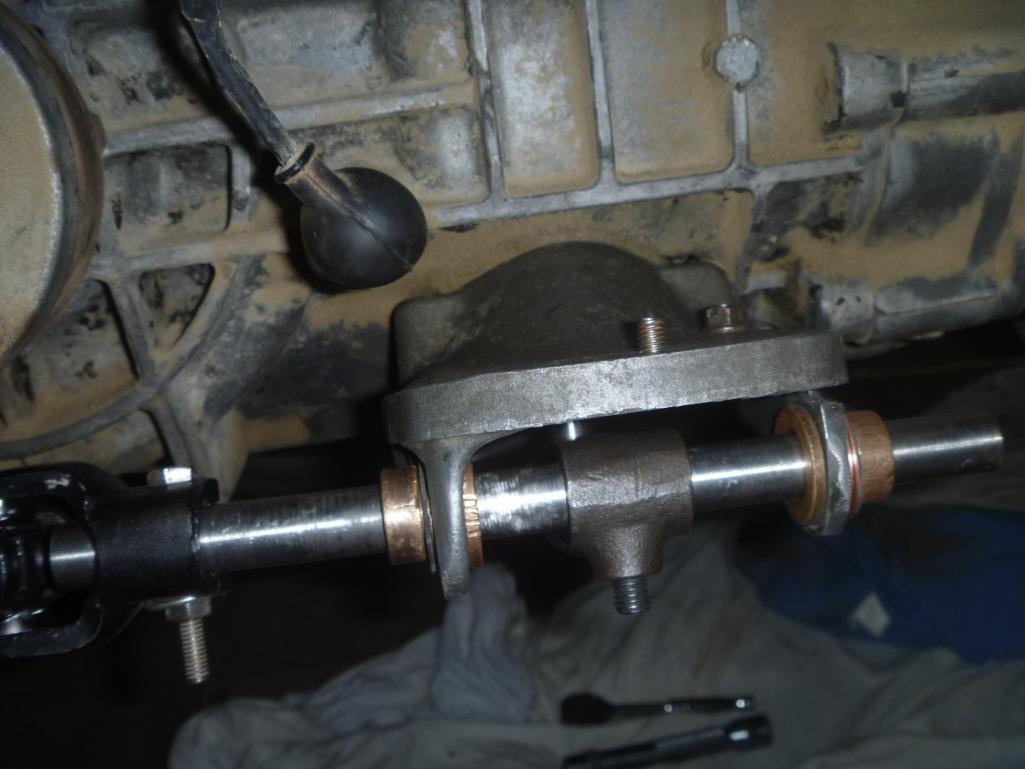 The above pic was while I was setting up placement of the rod. 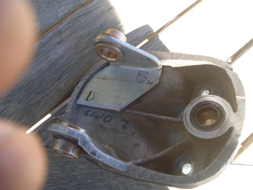 You will like how this setup works,with everything else correct this makes shifting very positive and much more accurate,interested to here your results and good luck. |
 |
|
| Montreal914 |
May 27 2018, 04:51 PM
Post
#6
|
|
Senior Member Group: Members Posts: 1,543 Joined: 8-August 10 From: Claremont, CA Member No.: 12,023 Region Association: Southern California |
Rear Shift Rod
Again, before cutting anything, I took a lot of reference dimensions as I wanted to ensure the bend in the rear rod was exactly in the same location to prevent any interference with the engine cross bar port. I first cut out the stock joint off the rod and established where the steering shaft end should be located to keep the geometry. 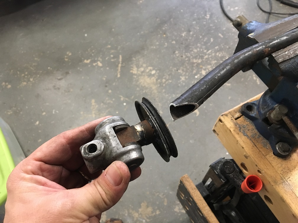 Then I prepared the tube to properly align the steering shaft spline 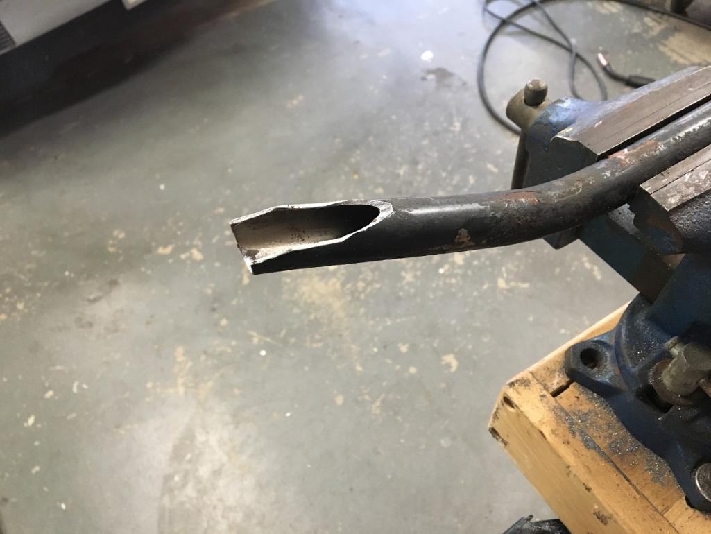 Final check of position, axis, and length of the spline. 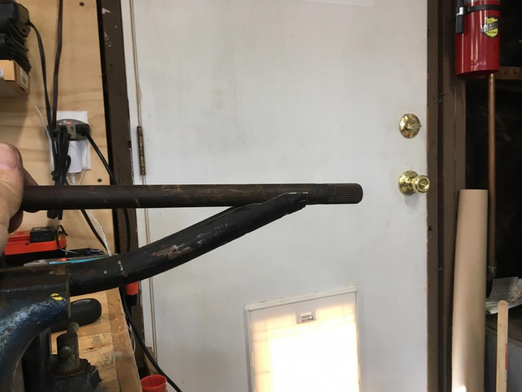 With the stub cut and held with only a couple of tacks, I began to assemble the rear part of the linkage onto the car. 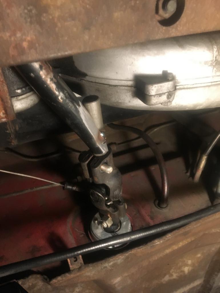 As we can see the position of the rear rod is the same as stock as the cone screw hole is lining up. That confirmed that the front part of the rod was good. It also allowed me to now establish how to cut the rear part of the rod to properly fit into the rear steering U-joint. 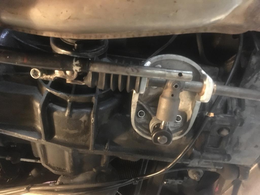 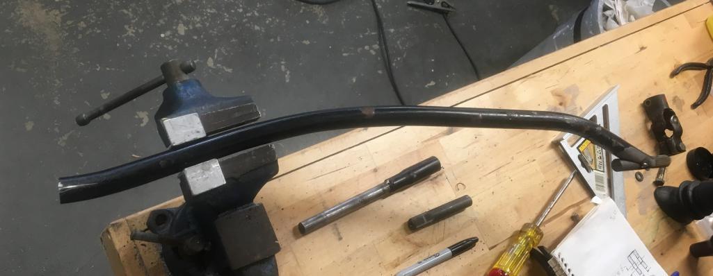 Detail of the rear cut of the tube and the steering shaft spline. Ready for tack welding and final check on the car. 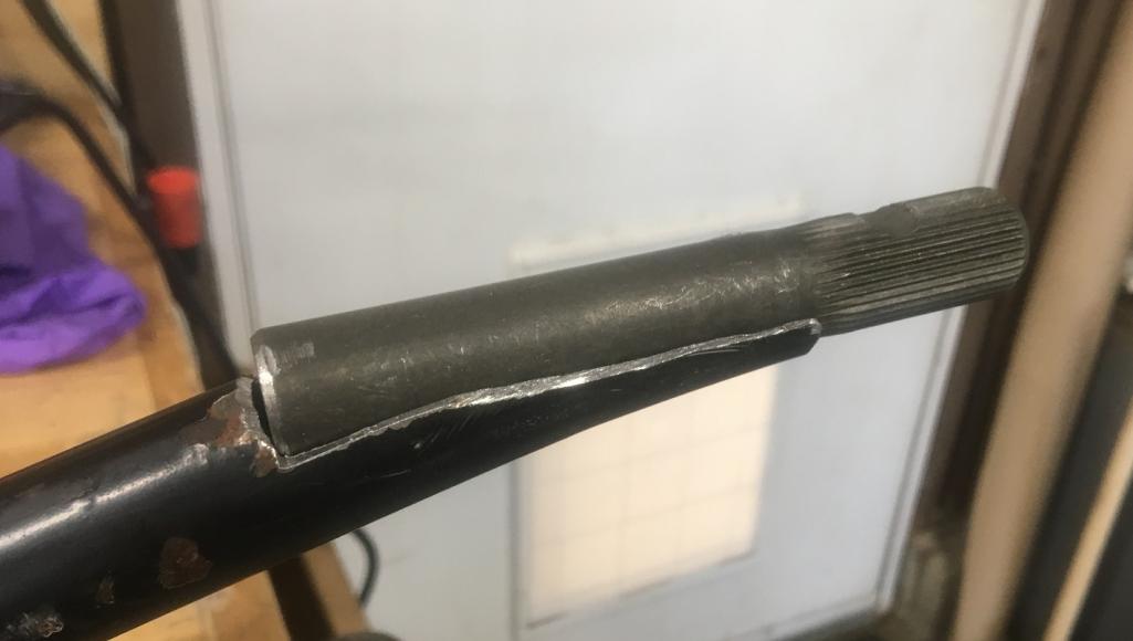 After welding grinding and paint, the rear rod is ready to be installed on the car. 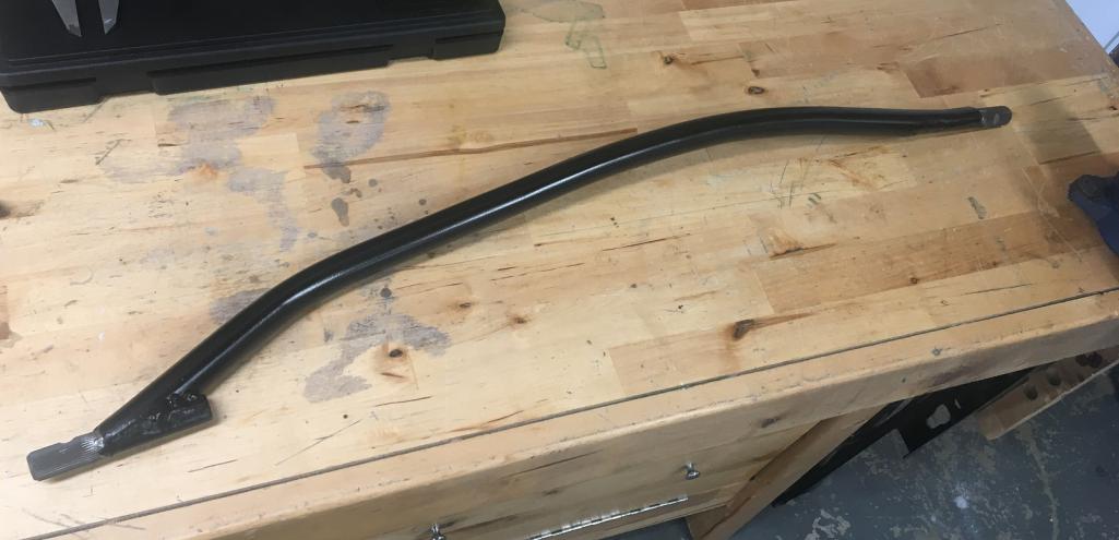 And the finished result of the shifter linkage. 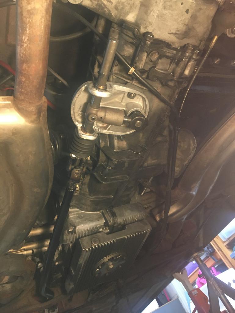 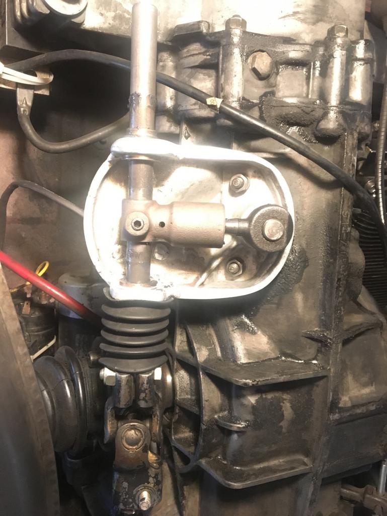 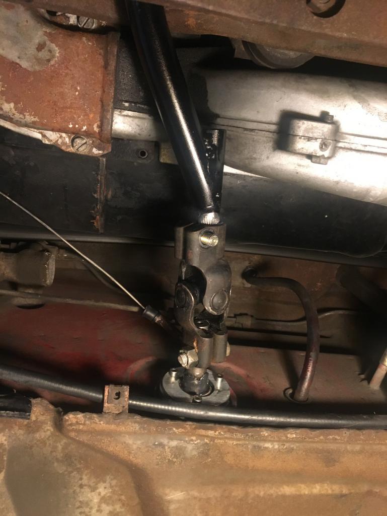 What I want to do next is to improve the protection of the U-joint. (IMG:style_emoticons/default/idea.gif) I was thinking about steering rack boot but I don't have any handy to check measurement. It would be great to find one that can snap onto the firewall like the original one. I was also thinking about printing a split part that could mount on the front of the rear shifter rod and connect to the stock boot attached to the firewall. Different ways to tackle this issue but I'm not too concerned for now, just happy with the result and shift feel. Now I need to work on the last part, the shifter itself... (IMG:style_emoticons/default/rolleyes.gif) Thank you for reading. (IMG:style_emoticons/default/beerchug.gif) |
|
|
|
| Montreal914 |
May 27 2018, 05:03 PM
Post
#7
|
|
Senior Member Group: Members Posts: 1,543 Joined: 8-August 10 From: Claremont, CA Member No.: 12,023 Region Association: Southern California |
Porschetub; I measured everything before modifying the console to make sure I was duplicating the original positioning of the shaft.
The only adjustment I have is at the shifter just like stock. The whole linkage can only go in one position due to the splines and grooves for the bolts in the U-joint. That's why I constantly double checked as I was building to keep the original positioning of the shift rods, or what's left of them to ensure no interference. It's now fully welded and works accordingly. Can completely be taken apart and rebuilt only one way without adjustment except final at the shifter (IMG:style_emoticons/default/driving.gif) |
|
|
|
| troth |
May 27 2018, 08:58 PM
Post
#8
|
|
Member Group: Members Posts: 151 Joined: 17-August 16 From: CT/WA Member No.: 20,305 Region Association: None |
I remember seeing something similar on Chris foley’s site.
http://www.tangerineracing.com/shiftlinkage.htm Your solution looks similar, but probably a bit less pricy. |
|
|
|
| Blue6 |
May 27 2018, 09:07 PM
Post
#9
|
|
Senior Member Group: Members Posts: 1,034 Joined: 3-October 13 From: SoCal Member No.: 16,470 Region Association: Southern California |
Nice work. Thank you for documenting and posting (IMG:style_emoticons/default/cheer.gif)
|
|
|
|
| mepstein |
May 27 2018, 09:42 PM
Post
#10
|
|
914-6 GT in waiting Group: Members Posts: 19,245 Joined: 19-September 09 From: Landenberg, PA/Wilmington, DE Member No.: 10,825 Region Association: MidAtlantic Region |
QUOTE(troth @ May 27 2018, 10:58 PM)  I remember seeing something similar on Chris foley’s site. http://www.tangerineracing.com/shiftlinkage.htm Your solution looks similar, but probably a bit less pricy. Just depends on how you value your time and what are your abilities. Montreal obviously put some hours into this and made a really nice set up. I was lucky enough to get the whole enchilada from JWest before they stopped production. |
|
|
|
| Montreal914 |
May 28 2018, 11:11 AM
Post
#11
|
|
Senior Member Group: Members Posts: 1,543 Joined: 8-August 10 From: Claremont, CA Member No.: 12,023 Region Association: Southern California |
Yep, didn't invent anything here, just made my own version of this setup while on a budget.
What I wanted was a welded rear console vs the bolt on conversion. I was inspired by Brant and Bigkat 83 who have also done it that way. Big thank to them for sharing of info. (IMG:style_emoticons/default/beerchug.gif) Next I would like to improve the shifter (use a cheap Mustang ?) and move it backward à la 914-8! (IMG:style_emoticons/default/chowtime.gif) Screenshot from PBase website: 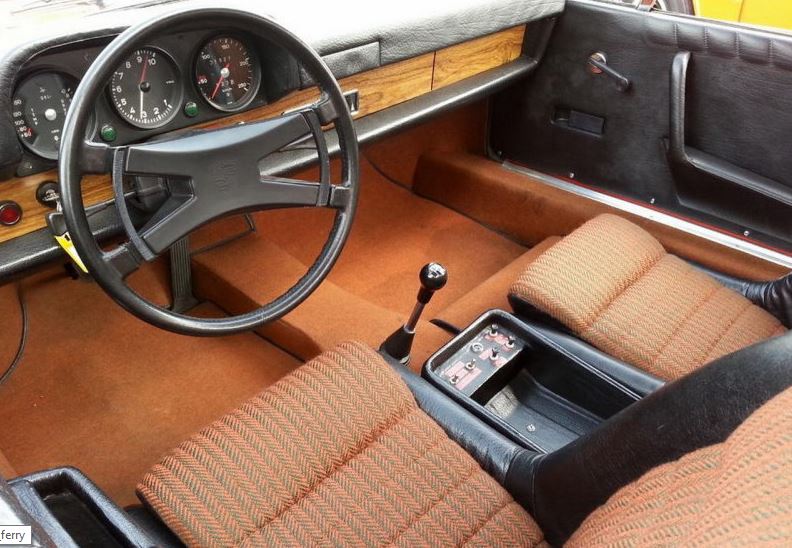 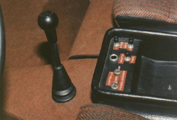 |
|
|
|
| stugray |
May 28 2018, 12:22 PM
Post
#12
|
|
Advanced Member Group: Members Posts: 3,824 Joined: 17-September 09 From: Longmont, CO Member No.: 10,819 Region Association: None |
QUOTE(troth @ May 27 2018, 08:58 PM) I remember seeing something similar on Chris foley’s site. http://www.tangerineracing.com/shiftlinkage.htm Your solution looks similar, but probably a bit less pricy. I can attest to the quality and operation of the unit above (TangerineRacing). My car has never shifted so cleanly - ever. But I have a Renn-shifter, TR firewall bushing, & TR shift linkage all fitted to a 71 chassis. The OPs solution looks perfectly executed and should be equivalent to the TR solution if not superior in the end (no chance for the console to shift, ever) But I also agree with the OP that welding those bushings perfectly without distorting the alignment of the bushings is to be left to only the most skiilled welders and even THEN requires some luck. Now welding the tabs and having a shop punch both holes all the way through is the perfect solution. Otherwise - Very well done! You will be happy with the effort. |
|
|
|
| Mark Henry |
May 28 2018, 12:31 PM
Post
#13
|
|
that's what I do! Group: Members Posts: 20,065 Joined: 27-December 02 From: Port Hope, Ontario Member No.: 26 Region Association: Canada |
QUOTE(mepstein @ May 27 2018, 11:42 PM) QUOTE(troth @ May 27 2018, 10:58 PM) I remember seeing something similar on Chris foley’s site. http://www.tangerineracing.com/shiftlinkage.htm Your solution looks similar, but probably a bit less pricy. Just depends on how you value your time and what are your abilities. Montreal obviously put some hours into this and made a really nice set up. (IMG:style_emoticons/default/agree.gif) Chris' setup is cheaper than the hours I have into mine, I did simular out of mild steel and made it bolt on for my /6 conversion. |
|
|
|
| jim_hoyland |
May 28 2018, 07:07 PM
Post
#14
|
|
Get that VIN ? Group: Members Posts: 9,265 Joined: 1-May 03 From: Sunset Beach, CA Member No.: 643 Region Association: Southern California |
Fantastic DIY project , Thanks for sharing the pics (IMG:style_emoticons/default/smile.gif)
|
|
|
|
| GregAmy |
May 29 2018, 06:41 AM
Post
#15
|
|
Advanced Member Group: Members Posts: 2,273 Joined: 22-February 13 From: Middletown CT Member No.: 15,565 Region Association: North East States |
You are clearly a man of fab talent and motivation!
Me, I did Chris' complete setup, soup to nuts. With beer. (I avoid power and machine tools that way...) |
|
|
|
| maf914 |
May 29 2018, 07:15 AM
Post
#16
|
|
Not a Guru! Group: Members Posts: 3,049 Joined: 30-April 03 From: Central Florida Member No.: 632 Region Association: None |
Excellent thread, Montreal914. Thanks for posting.
How are the results? How does it shift? We need details! (IMG:style_emoticons/default/laugh.gif) |
|
|
|
| UROpartsman |
May 29 2018, 11:00 AM
Post
#17
|
|
Member Group: Members Posts: 291 Joined: 22-October 15 From: Simi Valley, CA Member No.: 19,288 Region Association: None |
QUOTE(Montreal914 @ May 27 2018, 02:35 PM) Then my welder did his magic while taking his time and extra care to make sure the material didn't pull which would have resulted with bent tabs where bushings wouldn't have lined up and ruined the whole thing. Yes the preferred way of doing this would have been to weld first and machine after but that would have made the machining of the tabs more expensive due to an elaborate setup to hold the console. I would probably do it this way if I was doing it again, but since I had a good welder, he pulled it off nicely (IMG:style_emoticons/default/sunglasses.gif) Nicely done! Another way would be to use bushings with a slightly undersized ID, and then ream to final ID through both bushings at once to ensure bore alignment. King pin reamer Or with an adjustable reamer: King pin bushes reamed to a perfect fit |
|
|
|
| Montreal914 |
May 29 2018, 01:35 PM
Post
#18
|
|
Senior Member Group: Members Posts: 1,543 Joined: 8-August 10 From: Claremont, CA Member No.: 12,023 Region Association: Southern California |
QUOTE(maf914 @ May 29 2018, 06:15 AM) Excellent thread, Montreal914. Thanks for posting. How are the results? How does it shift? We need details! (IMG:style_emoticons/default/laugh.gif) It shifts very nice and smooth. (IMG:style_emoticons/default/piratenanner.gif) (IMG:style_emoticons/default/driving.gif) I'm very happy with it. Actually, it's so easy to move that the spring plate in the stock shifter that you press to be in the R-1 plane actually pushes the lever to the 4-5 plane when disengaging from 1st. I have to "catch it" to place it in the 2-3 plane when going from 1st to 2nd. This means I need something spring loaded on both sides like the Rennshift to keep the lever nominal in the 2-3 plane. More thinking ahead (IMG:style_emoticons/default/stirthepot.gif) |
|
|
|
| porschetub |
May 29 2018, 11:50 PM
Post
#19
|
|
Advanced Member Group: Members Posts: 4,697 Joined: 25-July 15 From: New Zealand Member No.: 18,995 Region Association: None |
QUOTE(Montreal914 @ May 30 2018, 07:35 AM) QUOTE(maf914 @ May 29 2018, 06:15 AM) Excellent thread, Montreal914. Thanks for posting. How are the results? How does it shift? We need details! (IMG:style_emoticons/default/laugh.gif) It shifts very nice and smooth. (IMG:style_emoticons/default/piratenanner.gif) (IMG:style_emoticons/default/driving.gif) I'm very happy with it. Actually, it's so easy to move that the spring plate in the stock shifter that you press to be in the R-1 plane actually pushes the lever to the 4-5 plane when disengaging from 1st. I have to "catch it" to place it in the 2-3 plane when going from 1st to 2nd. This means I need something spring loaded on both sides like the Rennshift to keep the lever nominal in the 2-3 plane. More thinking ahead (IMG:style_emoticons/default/stirthepot.gif) Wow great skills,love to have all that machinery so envious,hope it all works for out well .....should be cause you have done a great job (IMG:style_emoticons/default/beerchug.gif) (IMG:style_emoticons/default/beerchug.gif) . |
|
|
|
| Dr Evil |
Jun 1 2018, 01:47 PM
Post
#20
|
|
Send me your transmission! Group: Members Posts: 22,995 Joined: 21-November 03 From: Loveland, OH 45140 Member No.: 1,372 Region Association: MidAtlantic Region |
Very nice. Thanks for the pics and write up.
|
|
|
|
|
2 User(s) are reading this topic (1 Guests and 0 Anonymous Users)
1 Members: Montreal914

|
Lo-Fi Version | Time is now: 30th April 2024 - 08:50 AM |
Invision Power Board
v9.1.4 © 2024 IPS, Inc.