|
|
|
Porsche, and the Porsche crest are registered trademarks of Dr. Ing. h.c. F. Porsche AG.
This site is not affiliated with Porsche in any way. Its only purpose is to provide an online forum for car enthusiasts. All other trademarks are property of their respective owners. |
|
|

  |

| ChrisFoley |
 Aug 8 2018, 07:57 AM Aug 8 2018, 07:57 AM
Post
#141
|
|
I am Tangerine Racing  Group: Members Posts: 8,031 Joined: 29-January 03 From: Bolton, CT Member No.: 209 Region Association: None |
Some pics of the attachment points on my frame table (Slutty Bench).
Each pair is connected with a heavy crossmember bolted to the main frame. (spot welds holding crossmember to frame were removed after construction) The main frame is bolted together so it can be disassembled for long term storage. I currently have the table anchored to the floor with large turnbuckles so some chassis pulling can be done without the frame twisting. 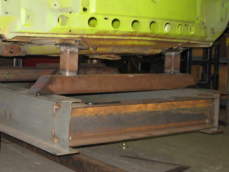 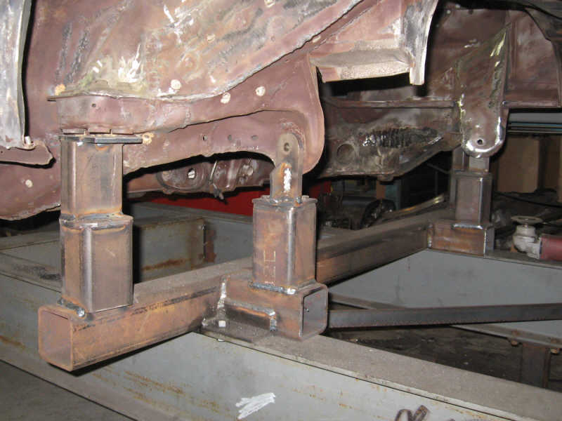 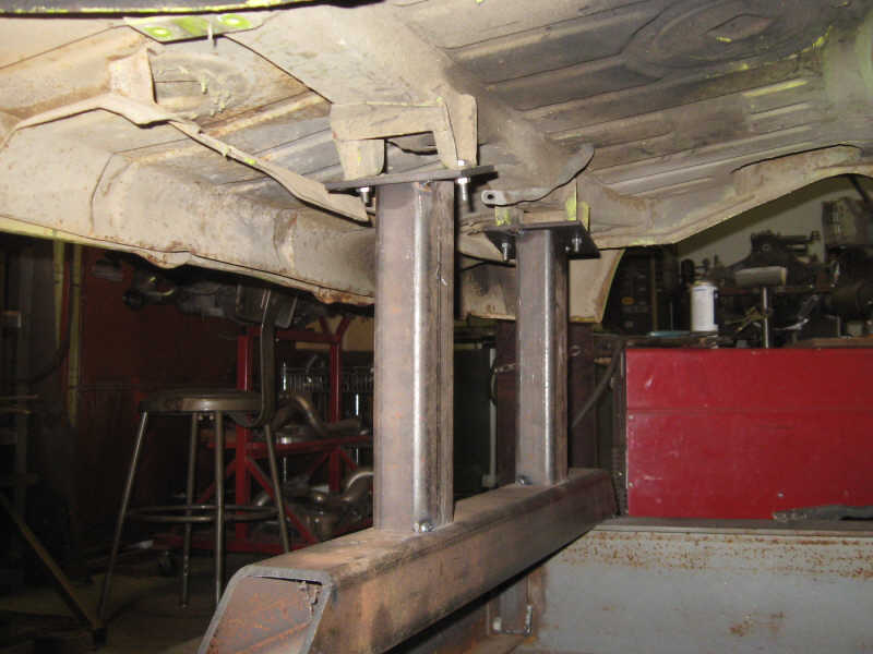 |
   |

 
|
| dan10101 |
Aug 8 2018, 08:42 AM
Post
#142
|
|
TORQUE-o-holic Group: Members Posts: 1,140 Joined: 29-April 03 From: Eagle Point, Or Member No.: 626 Region Association: Pacific Northwest |
Thanks Chris.
I forgot about your front swaybar when I was rationalizing on keeping the chassis. It would be an easy swap, but another thing to do. I really like your frame pictures. Especially mounting both pickup points together then attaching to the main frame. I'm going to do some more research before I start making arms. That way seems to be as solid as it gets. Do you have any pictures of pulling in action? I'm curious how you attach on jig side. I'm assuming you bolt to the pickup points on the car side to pull. I'm hoping not to need that, but I'm realistic. |
|
|
|
| ChrisFoley |
Aug 8 2018, 11:43 AM
Post
#143
|
|
I am Tangerine Racing Group: Members Posts: 8,031 Joined: 29-January 03 From: Bolton, CT Member No.: 209 Region Association: None |
QUOTE(dan10101 @ Aug 8 2018, 10:42 AM)  Do you have any pictures of pulling in action? I'm curious how you attach on jig side. I'm assuming you bolt to the pickup points on the car side to pull. Haven't done any hard pulls yet, but the chassis on the table is in need. We're too busy with other work to invest the time right now. I'll need to make anchor points on the floor to do the pulling since the table isn't built to attach heavy duty cantilever structures. Many years ago when I had to straighten my race car I took it to a shop that had a proper frame table. They let me do the work myself and just charged a small fee for the "rental". |
|
|
|
| ChrisFoley |
Aug 8 2018, 11:47 AM
Post
#144
|
|
I am Tangerine Racing Group: Members Posts: 8,031 Joined: 29-January 03 From: Bolton, CT Member No.: 209 Region Association: None |
QUOTE(dan10101 @ Aug 8 2018, 10:42 AM) I forgot about your front swaybar when I was rationalizing on keeping the chassis. It would be an easy swap, but another thing to do. I don't remember installing one of my anti-swaybars but it makes sense. The car previously had a 911 non-adjustable underbody bar. I did find pics from when we installed the de-cambered ball joints though. |
|
|
|
| dan10101 |
Aug 8 2018, 09:50 PM
Post
#145
|
|
TORQUE-o-holic Group: Members Posts: 1,140 Joined: 29-April 03 From: Eagle Point, Or Member No.: 626 Region Association: Pacific Northwest |
Chris, (or anyone) I would love to see any pictures you find of the Screamcicle.
One of my decisions is whether to repair the drivers side lower control arm or replace it. I know you made some changes to the ball joints and there are also elephant bushings I would like to save. I see the bottom cover is off the passenger lower ball joint and can't tell if it's bad or just missing the cover. I'll have a better idea once I pull it apart. The update for today is that I was able to mount the legs to the jig frame structure. Working upside down, I mounted the fixed legs on the inside of the laterals. then it was obvious that I should put the wheeled legs on the outer side of the laterals. Then later I'll add a bracing between the 2 legs which should be plenty strong for whichever leg is in use. 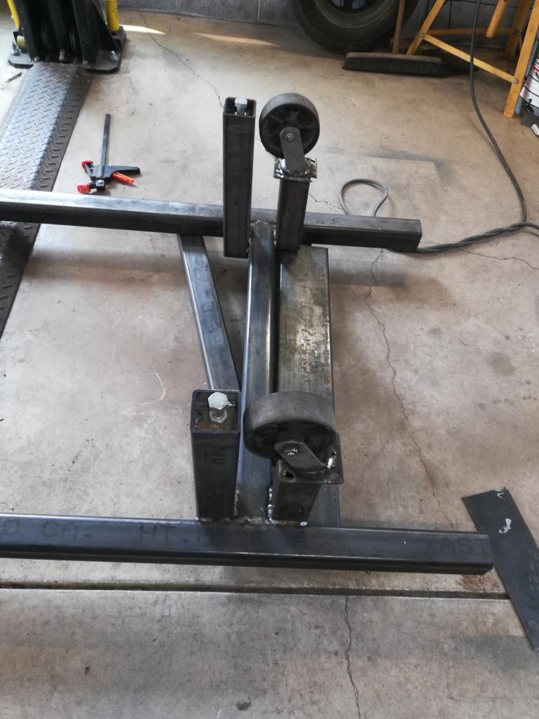 I also need to add some welds to the topside, now that it's flipped over and on it's feet. That was a challenge with to guys with bad backs. We were able to make it happen with jacks and leverage. 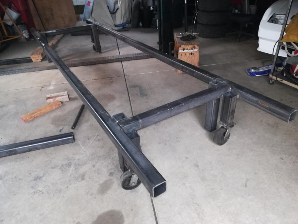 My cheap jig wheels from the metal scrap yard work excellent, All I had to do is cut the welds that kept them from turning 360 degrees. They even have zert fittings and do roll very smoothly. Well, reducing the size fixed the picture upload. They were less than 4mb, but smaller fixed it. |
|
|
|
| Andyrew |
Aug 8 2018, 10:02 PM
Post
#146
|
|
Spooling.... Please wait Group: Members Posts: 13,381 Joined: 20-January 03 From: Riverbank, Ca Member No.: 172 Region Association: Northern California |
Photos have to be under 4mb. you'll need to resize them. I use Ifranview.
Resize to 1920x.... |
|
|
|
| dan10101 |
Aug 8 2018, 11:18 PM
Post
#147
|
|
TORQUE-o-holic Group: Members Posts: 1,140 Joined: 29-April 03 From: Eagle Point, Or Member No.: 626 Region Association: Pacific Northwest |
QUOTE(Andyrew @ Aug 8 2018, 09:02 PM) Photos have to be under 4mb. you'll need to resize them. I use Ifranview. Resize to 1920x.... Well, smaller fixed it. I was less than 4mb, but oh well, I'll resize. Thanks |
|
|
|
| Andyrew |
Aug 9 2018, 07:24 AM
Post
#148
|
|
Spooling.... Please wait Group: Members Posts: 13,381 Joined: 20-January 03 From: Riverbank, Ca Member No.: 172 Region Association: Northern California |
With the bracing you mentioned I think it'll be good. I do think that maybe a 1"square tube as a diagnal brace along the jig might help.
Also what about doing two more feet in the middle of the jig? I know it's heavy duty 1/4", but I still worry about sagging. |
|
|
|
| Andyrew |
Aug 9 2018, 07:28 AM
Post
#149
|
|
Spooling.... Please wait Group: Members Posts: 13,381 Joined: 20-January 03 From: Riverbank, Ca Member No.: 172 Region Association: Northern California |
Also how about a sliding "L" bracket that bolts to the leg and allows for the jig to be more stable? It could also be boolted to the floor. I worry about it toppling with the chassis on it or at least not being perfectly stable.
With this you could still level the jig with the feet, but then attach these L brackets after all is said and positioned. |
|
|
|
| dan10101 |
Aug 9 2018, 09:13 AM
Post
#150
|
|
TORQUE-o-holic Group: Members Posts: 1,140 Joined: 29-April 03 From: Eagle Point, Or Member No.: 626 Region Association: Pacific Northwest |
QUOTE(Andyrew @ Aug 9 2018, 06:24 AM) With the bracing you mentioned I think it'll be good. I do think that maybe a 1"square tube as a diagnal brace along the jig might help. Also what about doing two more feet in the middle of the jig? I know it's heavy duty 1/4", but I still worry about sagging. I'll think about the diag.. Another leg will be a problem when I roll it out of the shop. i may have to to drag it up the hill and 4 legs would make it much easier. Most of the attachment points will be right where the legs are, so the weight in the middle will be minimal. |
|
|
|
| dan10101 |
Aug 9 2018, 09:20 AM
Post
#151
|
|
TORQUE-o-holic Group: Members Posts: 1,140 Joined: 29-April 03 From: Eagle Point, Or Member No.: 626 Region Association: Pacific Northwest |
QUOTE(Andyrew @ Aug 9 2018, 06:28 AM) Also how about a sliding "L" bracket that bolts to the leg and allows for the jig to be more stable? It could also be bolted to the floor. I worry about it toppling with the chassis on it or at least not being perfectly stable. With this you could still level the jig with the feet, but then attach these L brackets after all is said and positioned. This is a good idea. Chris mentioned attaching it to the floor for pulling. I may just wait to see if I have to pull something. I could put stabilizers on it to prevent rolling over, but we'll see if that's even necessary. I found this one that someone made. I wish mine was this light. it looks like good bracing to make it strong enough to stay in shape. 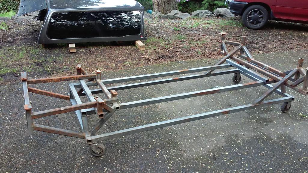 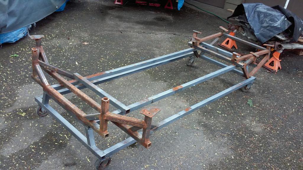 |
|
|
|
| Andyrew |
Aug 9 2018, 01:47 PM
Post
#152
|
|
Spooling.... Please wait Group: Members Posts: 13,381 Joined: 20-January 03 From: Riverbank, Ca Member No.: 172 Region Association: Northern California |
You could test deflection of the jig... Measure bottom of jig to bottom of floor. Place as much weight on the center of the jig as you can (Like 300lbs) and remeasure. That would give you an accurate deflection of your jig so you can determine if it needs extra help (IMG:style_emoticons/default/smile.gif)
|
|
|
|
| dan10101 |
Aug 9 2018, 05:13 PM
Post
#153
|
|
TORQUE-o-holic Group: Members Posts: 1,140 Joined: 29-April 03 From: Eagle Point, Or Member No.: 626 Region Association: Pacific Northwest |
Today was a day of making templates for the mounting plates.
Making the templates was easy. Cutting them out not so much. 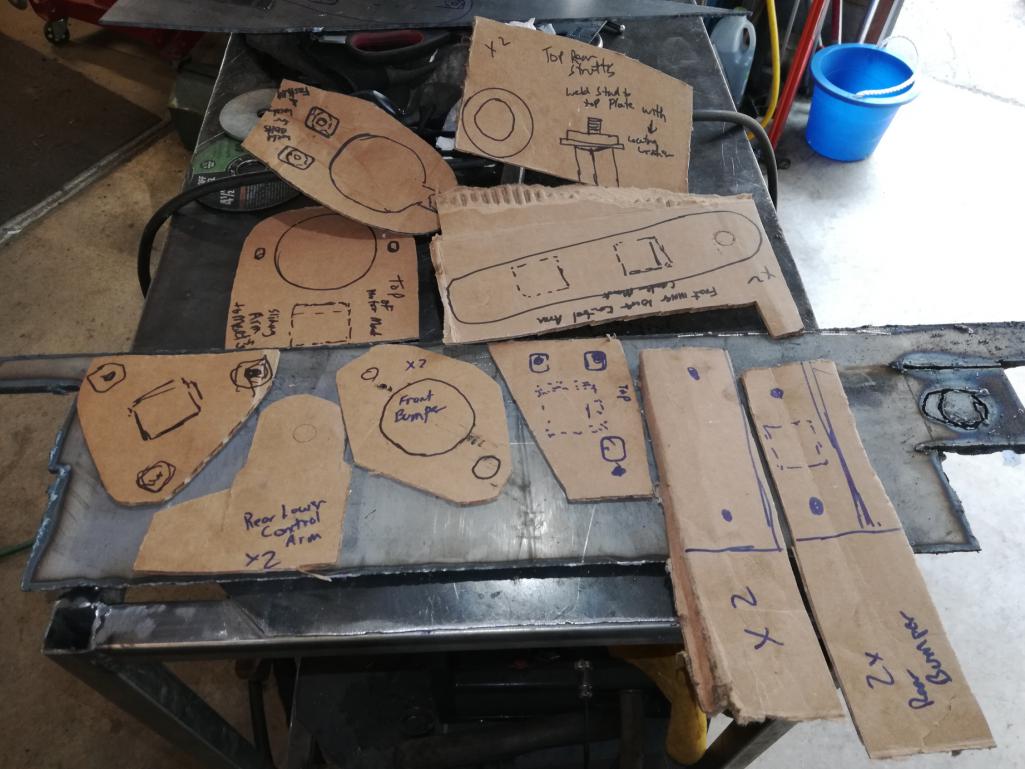 A plasma cutter certainly makes it easier to cut 1/4" plate. Probably didn't need to be that thick, but it's what I had leftover from a bumper build for my jeep. Tomorrow I get to grind, shape, drill and that's probably as far as I get. Also, found some angle iron and a 2x2" in my junk pile that I will be using for making cross bracing. I wasn't going to use the 1.5" x 1.5" square tubing but realizing how short they would be, I think they will be plenty strong. they are 1/8" thick. Plus some 1.25" square tubing that will slide into the 1.5" and fit snug. I can either bolt them or weld them to the distance I need. That is all, I'm going to go put some Aloa Vera on my welding sunburn. 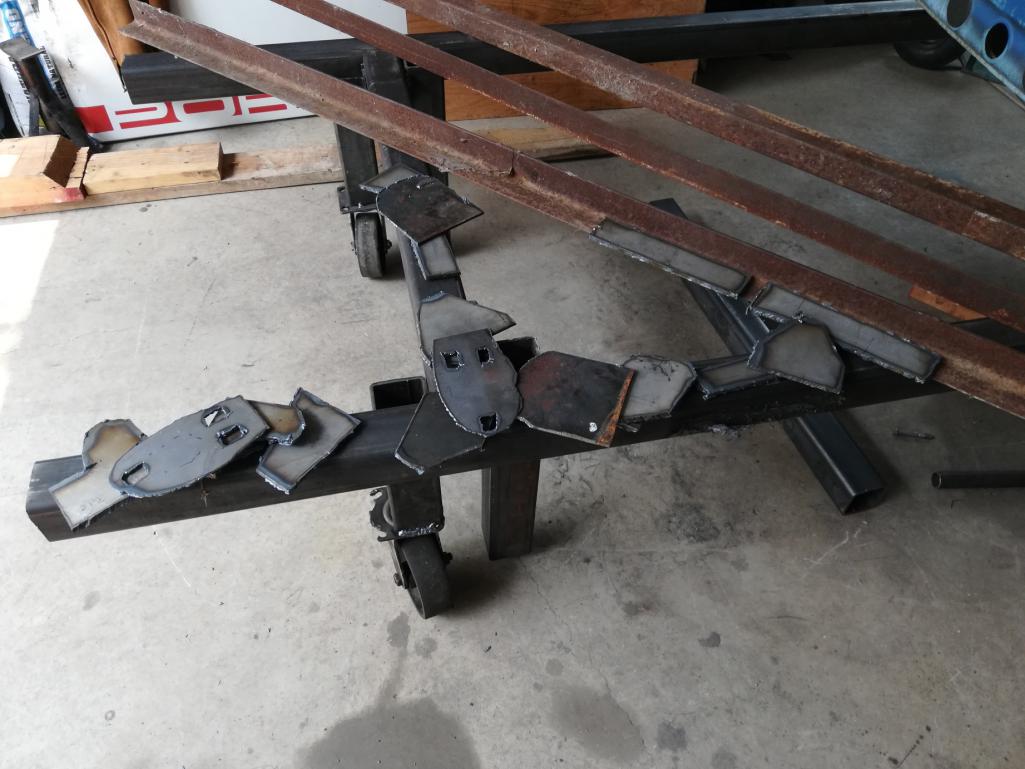 |
|
|
|
| tygaboy |
Aug 9 2018, 05:52 PM
Post
#154
|
|
914 Guru Group: Members Posts: 5,844 Joined: 6-October 15 From: Petaluma, CA Member No.: 19,241 Region Association: Northern California |
Dan - It looks like I'm late to the party but going forward, if it's of any help, I'd be happy to cut stuff for you on the plasma table. All I need are the dimensions...
Best of luck with your project! |
|
|
|
| dan10101 |
Aug 9 2018, 06:35 PM
Post
#155
|
|
TORQUE-o-holic Group: Members Posts: 1,140 Joined: 29-April 03 From: Eagle Point, Or Member No.: 626 Region Association: Pacific Northwest |
QUOTE(tygaboy @ Aug 9 2018, 04:52 PM) Dan - It looks like I'm late to the party but going forward, if it's of any help, I'd be happy to cut stuff for you on the plasma table. All I need are the dimensions... Best of luck with your project! Thanks Chris, I'm more a seat of the pants type of designer. Cut the cardboard til if fits, then cut it out of plate, and then grind it till it fits like the cardboard did. I'll keep you in mind if something else comes up. Well, you're usually in the back of my mind when i'm working. "what would Chris do in this situation", then do it completely wrong.. (IMG:style_emoticons/default/headbang.gif) It was a bit funny watching me hose down the weeds outside the shop every 20 minutes just in case a stray spark flew out there. anything to cut metal using Fire.. (IMG:style_emoticons/default/ar15.gif) I know they are rough, but I'll see what I can salvage. I do know I need to use long sleeves next time. need more aloa vera.. 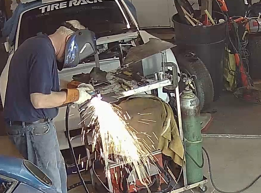 |
|
|
|
| sixnotfour |
Aug 10 2018, 01:47 PM
Post
#156
|
|
914 Wizard Group: Members Posts: 11,291 Joined: 12-September 04 Member No.: 2,744 Region Association: NineFourteenerVille |
that jig in the above pics was made by my buddies body shop,When they started it was a body dolly and I added the other points to do a front clip, no pulling , just cut and weld it was supported in the center when in was in use , the body gaps came out perfect... and chassis square..
oh ya it was attached to a straight chassis during the building of.. |
|
|
|
| dan10101 |
Aug 10 2018, 03:19 PM
Post
#157
|
|
TORQUE-o-holic Group: Members Posts: 1,140 Joined: 29-April 03 From: Eagle Point, Or Member No.: 626 Region Association: Pacific Northwest |
QUOTE(sixnotfour @ Aug 10 2018, 12:47 PM) that jig in the above pics was made by my buddies body shop,When they started it was a body dolly and I added the other points to do a front clip, no pulling , just cut and weld it was supported in the center when in was in use , the body gaps came out perfect... and chassis square.. oh ya it was attached to a straight chassis during the building of.. Very cool I'd love to hear more about how you mated the sheet metal together. |
|
|
|
| sixnotfour |
Aug 10 2018, 08:37 PM
Post
#158
|
|
914 Wizard Group: Members Posts: 11,291 Joined: 12-September 04 Member No.: 2,744 Region Association: NineFourteenerVille |
many cuts zig zagged and purposely.. factory spot welds intact.. there is a factory manual that shows factory front clip procedures ...I have it somewhere ..I moved 1300 miles... not pretty
|
|
|
|
| dan10101 |
Aug 10 2018, 09:51 PM
Post
#159
|
|
TORQUE-o-holic Group: Members Posts: 1,140 Joined: 29-April 03 From: Eagle Point, Or Member No.: 626 Region Association: Pacific Northwest |
So did you butt weld it back together, or overlap and then weld together?
Can you tell why i'm so curious? (IMG:style_emoticons/default/sawzall-smiley.gif) (IMG:style_emoticons/default/welder.gif) |
|
|
|
| dan10101 |
Aug 10 2018, 10:06 PM
Post
#160
|
|
TORQUE-o-holic Group: Members Posts: 1,140 Joined: 29-April 03 From: Eagle Point, Or Member No.: 626 Region Association: Pacific Northwest |
Today's update is minor, but still somewhat significant my mind. I place an order to Eastwood for some sheet metal tools. Also visited my local Harbor Freight. Even got a little honey dues done.
But still I managed to attach 4 plates to the car. Needed some tools to do that which slowed the day down a bit. 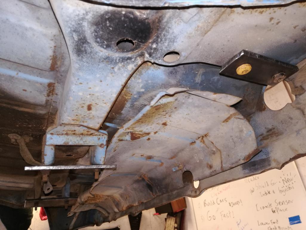 |
|
|
|
|
2 User(s) are reading this topic (2 Guests and 0 Anonymous Users)
0 Members:

|
Lo-Fi Version | Time is now: 21st July 2026 - 02:49 AM |
Invision Power Board
v9.1.4 © 2026 IPS, Inc.