|
|
|
Porsche, and the Porsche crest are registered trademarks of Dr. Ing. h.c. F. Porsche AG.
This site is not affiliated with Porsche in any way. Its only purpose is to provide an online forum for car enthusiasts. All other trademarks are property of their respective owners. |
|
|


| Superhawk996 |
 Dec 21 2018, 04:10 PM Dec 21 2018, 04:10 PM
Post
#21
|
|
914 Guru  Group: Members Posts: 7,891 Joined: 25-August 18 From: Woods of N. Idaho Member No.: 22,428 Region Association: Galt's Gulch |
I purchased my first 914 back in 1987 (1973 1.7L) and had that car for nearly a decade and I personally put over 100,000 miles on it before it ultimately fell victim to a negligent driver that drove into the back end of it at about 40 mph while the vehicle was stopped at a red light. That rear end crash totaled the vehicle but what is amazing is how well it crumpled (early crush zones!) due to the kink in the frame where the halfshafts are. Everyone walked away unharmed.
I replaced it with a 1991 Miata. Great car in its own right but I've always missed my 914. Purchased this "replacement" in May 2018 as a known poster child for a complete right side longitudinal rustoration. This vehicle had been put into storage inside a pole barn around 2004 as far as I can tell. Vehicle initially purchased in non-running condition: Engine couldn't be started. Transmission shift linkage was disconnected Half shafts and CV's were in pieces, and the wheel stubs were not installed therefore the vehicle couldn't even be rolled without risking having the rear wheel separate from within the bearing. Fiberglass laid into the floorpan . . . that can't be a good sign. Vehicle looks great . . . until I got under it. I spent the better part of the summer putting the items above back together and trying to confirm that it would: 1) Run under its own power 2) Drive though the neighborhood and shift though all gears. 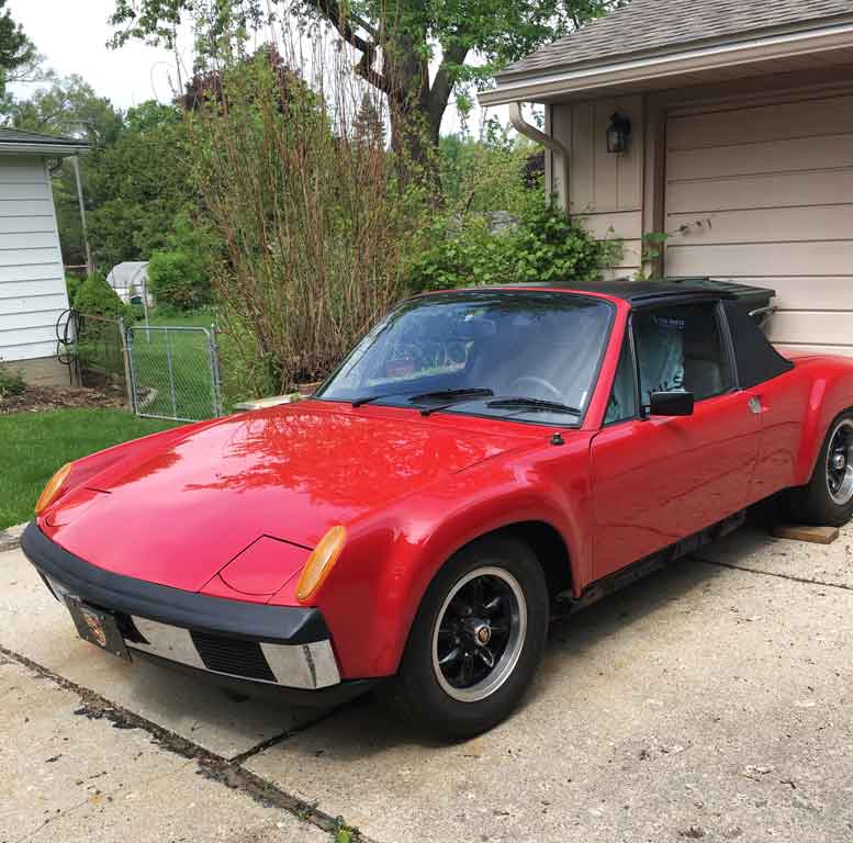 Looks pretty nice eh? Here is what is lurking underneath once the rockers came off. 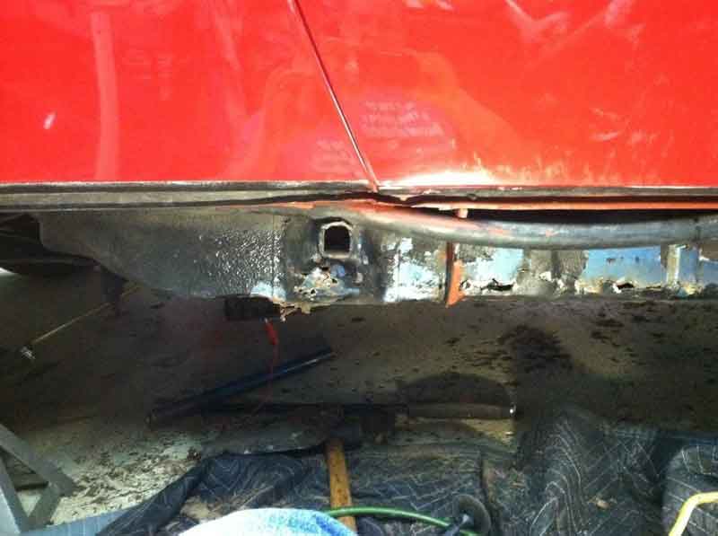 and when I started cutting back the rust. Oh my . . . . 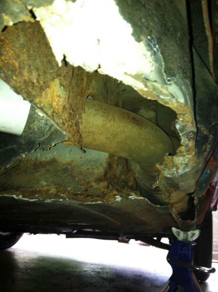 |
   |

 
|
Posts in this topic
 Superhawk996 1973 2.0L Rustoration Dec 21 2018, 04:10 PM
 Superhawk996 With a new found 914 where else would I go but to ... Dec 21 2018, 05:26 PM Cairo94507 :wttc: Well you found the best place in the world ... Dec 21 2018, 06:45 PM Superhawk996 In the process, I also fabricated up some door bra... Dec 21 2018, 06:52 PM Superhawk996 At this point, it became clear that there would be... Dec 21 2018, 07:01 PM Superhawk996 This project started with a few goals in mind:
1)... Dec 21 2018, 07:11 PM Superhawk996 Alright, so now is probably a good time to plug a ... Dec 21 2018, 08:07 PM Jamie You obviously know how to weld and have the tools,... Dec 21 2018, 08:24 PM Superhawk996 So what are the skeletons on this car that I'v... Dec 21 2018, 08:25 PM
Superhawk996 With a new found 914 where else would I go but to ... Dec 21 2018, 05:26 PM Cairo94507 :wttc: Well you found the best place in the world ... Dec 21 2018, 06:45 PM Superhawk996 In the process, I also fabricated up some door bra... Dec 21 2018, 06:52 PM Superhawk996 At this point, it became clear that there would be... Dec 21 2018, 07:01 PM Superhawk996 This project started with a few goals in mind:
1)... Dec 21 2018, 07:11 PM Superhawk996 Alright, so now is probably a good time to plug a ... Dec 21 2018, 08:07 PM Jamie You obviously know how to weld and have the tools,... Dec 21 2018, 08:24 PM Superhawk996 So what are the skeletons on this car that I'v... Dec 21 2018, 08:25 PM
 Dave_Darling
I'm trying to figure out a better way to do t... Dec 21 2018, 08:54 PM Superhawk996 How about this one? Mileage on the ODO is 60K (is... Dec 21 2018, 08:33 PM Superhawk996 All new vintage vehicle acquisitions come with sur... Dec 21 2018, 08:43 PM Superhawk996 This was another favorite. Some sort of home made... Dec 21 2018, 08:55 PM Superhawk996 Also found the driver side suspension console to h... Dec 21 2018, 09:08 PM Superhawk996 All right, one last fun post for the evening.
I... Dec 21 2018, 09:31 PM euro911 I really enjoy reading these kinds of brutal rusto... Dec 22 2018, 06:04 AM 76-914 That fiberglass added 40 lb's to the car. I al... Dec 22 2018, 08:51 AM bbrock :wttc: Anyone crazy enough to save a rusted out ba... Dec 22 2018, 09:40 AM Superhawk996 Thank you for the kind words of encouragement... Dec 23 2018, 02:25 PM Superhawk996 Overall pretty happy with progress so far.
Floo... Dec 23 2018, 10:05 PM bbrock
Then put passenger side door back on to gauge doo... Dec 23 2018, 11:03 PM Superhawk996
Then put passenger side door back on to gauge do... Dec 23 2018, 11:22 PM bbrock
That was the 1st time for me with pulling my back... Dec 23 2018, 11:37 PM jmitro Alternatively, if you look carefully, you may fin... Dec 29 2018, 09:51 PM Superhawk996 Also did some more removal of the rear frame ... Dec 23 2018, 10:32 PM Superhawk996 So after all that, I decided to take a look at how... Dec 23 2018, 10:42 PM sixnotfour way to dive in... :wttc:
:first: Dec 23 2018, 10:46 PM Superhawk996 So here is a fun picture of my original 914 back i... Dec 23 2018, 11:53 PM whitetwinturbo ............I'm popped out just reading this t... Dec 27 2018, 12:00 AM Superhawk996 Getting back to work after a few days off.
Slow... Dec 29 2018, 09:02 PM Superhawk996 Posted a video up on YouTube. Posted as much for ... Dec 29 2018, 09:31 PM Superhawk996 Deleted duplicate post - oops! Dec 29 2018, 09:34 PM Superhawk996 Spent a bit of time getting the 914 clock working.... Jan 1 2019, 12:08 PM bbrock Happy New Year! Thanks for posting your clock... Jan 1 2019, 01:41 PM Superhawk996
I'm curious about the thermal fuse. Is the... Jan 1 2019, 02:42 PM euro911 Is there enough room inside the housing to solder ... Jan 1 2019, 03:24 PM bbrock
Littlefuse also has miniature ceramic fuses with ... Jan 1 2019, 06:42 PM Dion Just spotted this thread. Nice work! & Go... Jan 1 2019, 06:25 PM Superhawk996 I suppose you could add in one of those miniature ... Jan 3 2019, 07:58 PM FourBlades Great looking restoration!
Check out this pag... Jan 4 2019, 08:40 AM Superhawk996
Great looking restoration!
Check out this pa... Jan 19 2019, 11:35 AM bbrock Thanks for the details on the clock. Makes sense ... Jan 4 2019, 08:49 AM Superhawk996 Happy to be of help!
I ordered some special... Jan 5 2019, 05:59 PM Superhawk996 Didn't get much done that looks impressive.
... Jan 5 2019, 06:07 PM Superhawk996 Have not posted in a while but I've been worki... Jan 19 2019, 12:08 PM Superhawk996 The trailing arm mount on my car came with one of ... Jan 19 2019, 12:34 PM euro911 I drill two holes in the bottom of each jack point... Jan 19 2019, 04:44 PM Superhawk996
I drill two holes in the bottom of each jack poin... Jan 26 2019, 10:11 AM Superhawk996 :headbang:
Having a rough go of getting the trai... Jan 26 2019, 10:32 AM Superhawk996 Also picked up some front brake calibers from PMB ... Jan 26 2019, 10:47 AM Superhawk996 Update on the trailing arm mount madness:
Laser p... Jan 30 2019, 09:59 AM Superhawk996 Back to work. Last couple of weekends have been l... Feb 9 2019, 06:24 PM mgphoto
I bought the same part through Sierra Madre col... Mar 17 2019, 10:11 AM R8CERX WOW--AWESOME work!! :cheer:
Cant wait to ... Mar 1 2019, 02:19 PM Superhawk996 It's been a while since I posted. Things have... Mar 15 2019, 09:45 PM Superhawk996 Although I had a rough mock up there is still more... Mar 15 2019, 10:08 PM Superhawk996 The other thing that has derailed my effort to get... Mar 15 2019, 10:19 PM bbrock
But the more I got to thinking about doing a from... Mar 15 2019, 10:41 PM Superhawk996 @porscheaddic
Came to my rescue and provided a ... Mar 15 2019, 10:32 PM Superhawk996 I'll end up with some odds and ends that I won... Mar 15 2019, 10:37 PM Superhawk996 @bbrock
You've set a pretty high bar. I... Mar 15 2019, 10:44 PM Superhawk996 @mgphoto
:headbanger: Nice project photo. I ... Mar 17 2019, 10:20 AM mgphoto I would like to see a photo of your car sort of th... Mar 17 2019, 10:41 AM Superhawk996
I would like to see a photo of your car sort of t... Mar 17 2019, 11:42 AM bbrock
My thought is the 2nd hole might have something ... Mar 17 2019, 12:20 PM mgphoto
[quote name='mgphoto' post='2697526' date='Mar 17... Mar 20 2019, 11:54 AM Superhawk996 Photo of passenger side donor sheet metal rough tr... Mar 17 2019, 11:45 AM Superhawk996 Time to post a little progress for March.
Here ... Apr 6 2019, 04:17 PM bbrock Just your mark-up is a work of art. That's qu... Apr 6 2019, 06:02 PM Superhawk996
Just your mark-up is a work of art. That's q... Apr 6 2019, 06:26 PM Superhawk996 I was saving my effort doing complex metal forming... Apr 6 2019, 06:35 PM Superhawk996 Been a little bit slow posting lately. Spring and... Apr 23 2019, 07:31 AM Superhawk996 This cowl area has taken way too much time.
A f... Apr 23 2019, 07:52 AM Superhawk996 The other thing that led to rushing the job was al... Apr 23 2019, 08:15 AM tygaboy :agree: with all the "can't see = can... Apr 23 2019, 08:32 AM Superhawk996
:agree: with all the "can't see = can... Apr 23 2019, 08:48 AM Superhawk996 These are the easy ones. Just a quick dab or two ... Apr 23 2019, 08:35 AM Superhawk996 The other work that has started in April is beginn... Apr 23 2019, 09:04 AM Superhawk996 Here is a bit of previous work. I removed the tun... Apr 23 2019, 09:27 AM Superhawk996 For all you guys that think just a little rust in ... Apr 23 2019, 09:34 AM Dave_Darling Would a copper backer help with the blow-through i... Apr 23 2019, 12:05 PM Superhawk996
Would a copper backer help with the blow-through ... Apr 23 2019, 02:02 PM Superhawk996 Well since I'm not supposed to be doing any he... Apr 28 2019, 04:49 PM Dave_Darling
Worse than the rust debris / garbage there is som... Apr 28 2019, 07:02 PM bbrock
Worse than the rust debris / garbage there is so... Apr 28 2019, 07:31 PM restore2seater I have no idea what this is or where it came from.... Apr 29 2019, 08:04 AM Superhawk996 On a more positive note. Most of the other engine... Apr 28 2019, 05:03 PM bbrock When I rebuilt my short block, I filled all the ga... Apr 28 2019, 05:13 PM Superhawk996 I've gotta admit JB weld is pretty good at res... Apr 28 2019, 05:24 PM Superhawk996 Here is the Miata in it's prime as a MUV. Mia... Apr 28 2019, 05:27 PM bbrock
Here is the Miata in it's prime as a MUV. Mi... Apr 28 2019, 05:57 PM Superhawk996 @bbrock
Wait a few years, but, you definitely sh... Apr 28 2019, 06:12 PM Superhawk996 Here's a video of the posted Miata turning 220... Apr 28 2019, 06:18 PM bbrock
Here's a video of the posted Miata turning 22... Apr 28 2019, 07:36 PM Tenner A few posts earlier, you've been talked about ... Apr 29 2019, 02:55 AM injunmort to fill pits in rocker covers, try boiler cement. ... Apr 29 2019, 04:33 AM Superhawk996 @Tenner
[b]Looks like nice work. You most defin... Apr 29 2019, 04:44 AM bbrock
@[url=http://www.914world.com/bbs2/index.php?show... Apr 29 2019, 08:11 AM injunmort brake piston Apr 29 2019, 10:18 AM Superhawk996
brake piston
Good guess . . . but it would ha... Apr 29 2019, 11:40 AM
Dave_Darling
I'm trying to figure out a better way to do t... Dec 21 2018, 08:54 PM Superhawk996 How about this one? Mileage on the ODO is 60K (is... Dec 21 2018, 08:33 PM Superhawk996 All new vintage vehicle acquisitions come with sur... Dec 21 2018, 08:43 PM Superhawk996 This was another favorite. Some sort of home made... Dec 21 2018, 08:55 PM Superhawk996 Also found the driver side suspension console to h... Dec 21 2018, 09:08 PM Superhawk996 All right, one last fun post for the evening.
I... Dec 21 2018, 09:31 PM euro911 I really enjoy reading these kinds of brutal rusto... Dec 22 2018, 06:04 AM 76-914 That fiberglass added 40 lb's to the car. I al... Dec 22 2018, 08:51 AM bbrock :wttc: Anyone crazy enough to save a rusted out ba... Dec 22 2018, 09:40 AM Superhawk996 Thank you for the kind words of encouragement... Dec 23 2018, 02:25 PM Superhawk996 Overall pretty happy with progress so far.
Floo... Dec 23 2018, 10:05 PM bbrock
Then put passenger side door back on to gauge doo... Dec 23 2018, 11:03 PM Superhawk996
Then put passenger side door back on to gauge do... Dec 23 2018, 11:22 PM bbrock
That was the 1st time for me with pulling my back... Dec 23 2018, 11:37 PM jmitro Alternatively, if you look carefully, you may fin... Dec 29 2018, 09:51 PM Superhawk996 Also did some more removal of the rear frame ... Dec 23 2018, 10:32 PM Superhawk996 So after all that, I decided to take a look at how... Dec 23 2018, 10:42 PM sixnotfour way to dive in... :wttc:
:first: Dec 23 2018, 10:46 PM Superhawk996 So here is a fun picture of my original 914 back i... Dec 23 2018, 11:53 PM whitetwinturbo ............I'm popped out just reading this t... Dec 27 2018, 12:00 AM Superhawk996 Getting back to work after a few days off.
Slow... Dec 29 2018, 09:02 PM Superhawk996 Posted a video up on YouTube. Posted as much for ... Dec 29 2018, 09:31 PM Superhawk996 Deleted duplicate post - oops! Dec 29 2018, 09:34 PM Superhawk996 Spent a bit of time getting the 914 clock working.... Jan 1 2019, 12:08 PM bbrock Happy New Year! Thanks for posting your clock... Jan 1 2019, 01:41 PM Superhawk996
I'm curious about the thermal fuse. Is the... Jan 1 2019, 02:42 PM euro911 Is there enough room inside the housing to solder ... Jan 1 2019, 03:24 PM bbrock
Littlefuse also has miniature ceramic fuses with ... Jan 1 2019, 06:42 PM Dion Just spotted this thread. Nice work! & Go... Jan 1 2019, 06:25 PM Superhawk996 I suppose you could add in one of those miniature ... Jan 3 2019, 07:58 PM FourBlades Great looking restoration!
Check out this pag... Jan 4 2019, 08:40 AM Superhawk996
Great looking restoration!
Check out this pa... Jan 19 2019, 11:35 AM bbrock Thanks for the details on the clock. Makes sense ... Jan 4 2019, 08:49 AM Superhawk996 Happy to be of help!
I ordered some special... Jan 5 2019, 05:59 PM Superhawk996 Didn't get much done that looks impressive.
... Jan 5 2019, 06:07 PM Superhawk996 Have not posted in a while but I've been worki... Jan 19 2019, 12:08 PM Superhawk996 The trailing arm mount on my car came with one of ... Jan 19 2019, 12:34 PM euro911 I drill two holes in the bottom of each jack point... Jan 19 2019, 04:44 PM Superhawk996
I drill two holes in the bottom of each jack poin... Jan 26 2019, 10:11 AM Superhawk996 :headbang:
Having a rough go of getting the trai... Jan 26 2019, 10:32 AM Superhawk996 Also picked up some front brake calibers from PMB ... Jan 26 2019, 10:47 AM Superhawk996 Update on the trailing arm mount madness:
Laser p... Jan 30 2019, 09:59 AM Superhawk996 Back to work. Last couple of weekends have been l... Feb 9 2019, 06:24 PM mgphoto
I bought the same part through Sierra Madre col... Mar 17 2019, 10:11 AM R8CERX WOW--AWESOME work!! :cheer:
Cant wait to ... Mar 1 2019, 02:19 PM Superhawk996 It's been a while since I posted. Things have... Mar 15 2019, 09:45 PM Superhawk996 Although I had a rough mock up there is still more... Mar 15 2019, 10:08 PM Superhawk996 The other thing that has derailed my effort to get... Mar 15 2019, 10:19 PM bbrock
But the more I got to thinking about doing a from... Mar 15 2019, 10:41 PM Superhawk996 @porscheaddic
Came to my rescue and provided a ... Mar 15 2019, 10:32 PM Superhawk996 I'll end up with some odds and ends that I won... Mar 15 2019, 10:37 PM Superhawk996 @bbrock
You've set a pretty high bar. I... Mar 15 2019, 10:44 PM Superhawk996 @mgphoto
:headbanger: Nice project photo. I ... Mar 17 2019, 10:20 AM mgphoto I would like to see a photo of your car sort of th... Mar 17 2019, 10:41 AM Superhawk996
I would like to see a photo of your car sort of t... Mar 17 2019, 11:42 AM bbrock
My thought is the 2nd hole might have something ... Mar 17 2019, 12:20 PM mgphoto
[quote name='mgphoto' post='2697526' date='Mar 17... Mar 20 2019, 11:54 AM Superhawk996 Photo of passenger side donor sheet metal rough tr... Mar 17 2019, 11:45 AM Superhawk996 Time to post a little progress for March.
Here ... Apr 6 2019, 04:17 PM bbrock Just your mark-up is a work of art. That's qu... Apr 6 2019, 06:02 PM Superhawk996
Just your mark-up is a work of art. That's q... Apr 6 2019, 06:26 PM Superhawk996 I was saving my effort doing complex metal forming... Apr 6 2019, 06:35 PM Superhawk996 Been a little bit slow posting lately. Spring and... Apr 23 2019, 07:31 AM Superhawk996 This cowl area has taken way too much time.
A f... Apr 23 2019, 07:52 AM Superhawk996 The other thing that led to rushing the job was al... Apr 23 2019, 08:15 AM tygaboy :agree: with all the "can't see = can... Apr 23 2019, 08:32 AM Superhawk996
:agree: with all the "can't see = can... Apr 23 2019, 08:48 AM Superhawk996 These are the easy ones. Just a quick dab or two ... Apr 23 2019, 08:35 AM Superhawk996 The other work that has started in April is beginn... Apr 23 2019, 09:04 AM Superhawk996 Here is a bit of previous work. I removed the tun... Apr 23 2019, 09:27 AM Superhawk996 For all you guys that think just a little rust in ... Apr 23 2019, 09:34 AM Dave_Darling Would a copper backer help with the blow-through i... Apr 23 2019, 12:05 PM Superhawk996
Would a copper backer help with the blow-through ... Apr 23 2019, 02:02 PM Superhawk996 Well since I'm not supposed to be doing any he... Apr 28 2019, 04:49 PM Dave_Darling
Worse than the rust debris / garbage there is som... Apr 28 2019, 07:02 PM bbrock
Worse than the rust debris / garbage there is so... Apr 28 2019, 07:31 PM restore2seater I have no idea what this is or where it came from.... Apr 29 2019, 08:04 AM Superhawk996 On a more positive note. Most of the other engine... Apr 28 2019, 05:03 PM bbrock When I rebuilt my short block, I filled all the ga... Apr 28 2019, 05:13 PM Superhawk996 I've gotta admit JB weld is pretty good at res... Apr 28 2019, 05:24 PM Superhawk996 Here is the Miata in it's prime as a MUV. Mia... Apr 28 2019, 05:27 PM bbrock
Here is the Miata in it's prime as a MUV. Mi... Apr 28 2019, 05:57 PM Superhawk996 @bbrock
Wait a few years, but, you definitely sh... Apr 28 2019, 06:12 PM Superhawk996 Here's a video of the posted Miata turning 220... Apr 28 2019, 06:18 PM bbrock
Here's a video of the posted Miata turning 22... Apr 28 2019, 07:36 PM Tenner A few posts earlier, you've been talked about ... Apr 29 2019, 02:55 AM injunmort to fill pits in rocker covers, try boiler cement. ... Apr 29 2019, 04:33 AM Superhawk996 @Tenner
[b]Looks like nice work. You most defin... Apr 29 2019, 04:44 AM bbrock
@[url=http://www.914world.com/bbs2/index.php?show... Apr 29 2019, 08:11 AM injunmort brake piston Apr 29 2019, 10:18 AM Superhawk996
brake piston
Good guess . . . but it would ha... Apr 29 2019, 11:40 AM  |
1 User(s) are reading this topic (1 Guests and 0 Anonymous Users)
0 Members:

|
Lo-Fi Version | Time is now: 16th June 2026 - 10:04 AM |
Invision Power Board
v9.1.4 © 2026 IPS, Inc.