|
|
|
Porsche, and the Porsche crest are registered trademarks of Dr. Ing. h.c. F. Porsche AG.
This site is not affiliated with Porsche in any way. Its only purpose is to provide an online forum for car enthusiasts. All other trademarks are property of their respective owners. |
|
|

  |

| Cairo94507 |
 Dec 10 2021, 10:02 AM Dec 10 2021, 10:02 AM
Post
#461
|
|
Michael  Group: Members Posts: 10,634 Joined: 1-November 08 From: Auburn, CA Member No.: 9,712 Region Association: Northern California |
Nice looking patch panel. (IMG:style_emoticons/default/beerchug.gif)
|
   |

 
|
| Superhawk996 |
Dec 13 2021, 01:57 PM
Post
#462
|
|
914 Guru Group: Members Posts: 7,840 Joined: 25-August 18 From: Woods of N. Idaho Member No.: 22,428 Region Association: Galt's Gulch |
So I'm pretty happy with the final installation of the bulkhead patch panel. After some careful fitting and very slow welding to prevent warping I think the character lines match nicely.
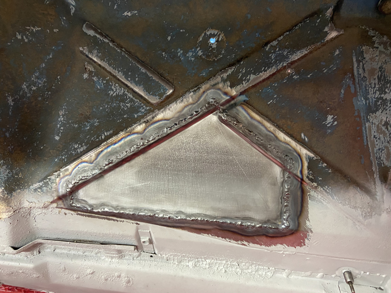 Used a copper backer to assure full pentration welds without blowing holes. 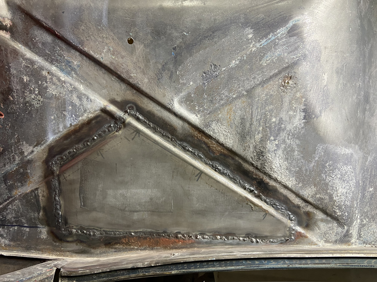 And now it's on to the next step. Clean up weld beads then need to go back and reapply Ospho to reactivate the Ospho previously left on the bulkhead for rust control. Then I can finish the cyclic process of applying Ospho, using a wire wheel to dig out rust from the pitting, and finally neutralizing the whole panel prior to a 2K primer.  I also was able to knock out some bead blasting of a few other parts before I had to replace the bead. It sure leaves a nice finish but man, glass bead wears out so quickly. 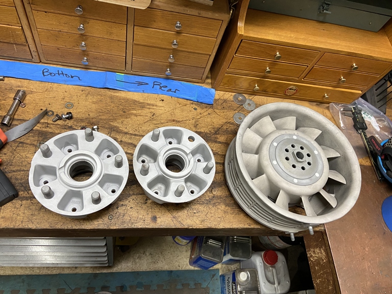 And then today - new hardware from BelMetric arrived. Time to restock my bolt cabinets looking ahead to a time when parts might actually start to go back on the car. That day is still a long way in the future but now I'm ready with proper yellow zinc hardware. 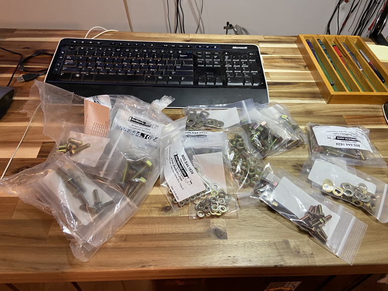 |
|
|
|
| Superhawk996 |
Dec 23 2021, 05:26 PM
Post
#463
|
|
914 Guru Group: Members Posts: 7,840 Joined: 25-August 18 From: Woods of N. Idaho Member No.: 22,428 Region Association: Galt's Gulch |
Finally - A Major Milestone (IMG:style_emoticons/default/piratenanner.gif)
Got the inner rear suspension console properly located (I think). (IMG:style_emoticons/default/blink.gif) 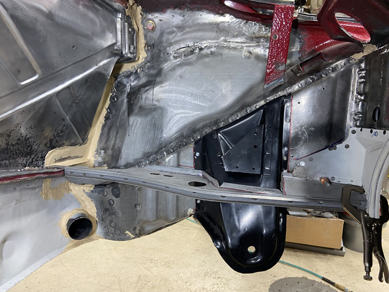 I've been stressing over how to do this the most accurately. Ultimately, I will install rear trailing arms to verify proper toe adjustment, and camber before I do final welding. Jeff Hail's measurements triangulate off the hole in the middle of the rear bulkhead. Being a little OCD I wanted to eliminate all variability in how I use the tape measure. I decided to machine up a little Bobbin that is a perfect fit to the OEM hole. In the center of the bobbin, there is a recess just big enough to nest a 1/8" welding rod. This allows me to mark the welding rod and get a much more accurate and repeatable measurement than I felt I could get with a tape measure. Here is the little bobbin turned up on the lathe. 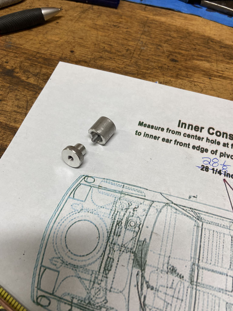 In position in the engine compartment 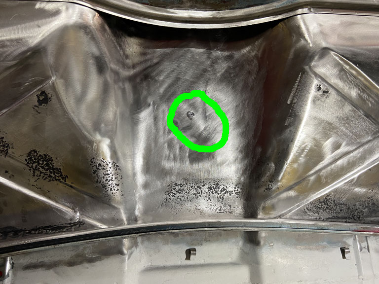 And how it is held in place on the interior 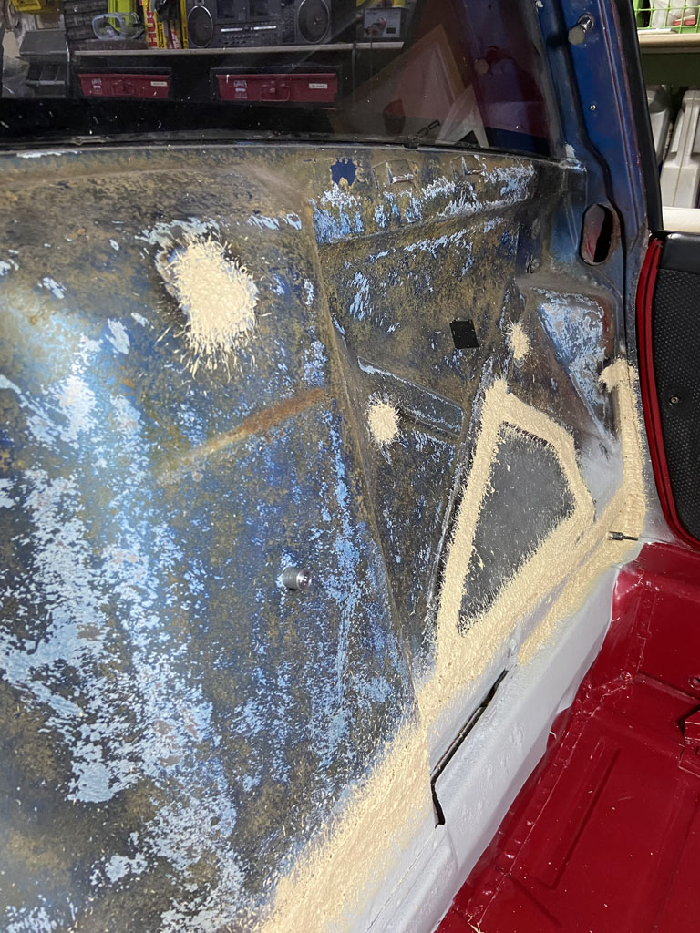 This worked out wonderfully in my opinion. I worked with two pieces of welding rod. The first was cut to 33.5" and was used to verify the Jeff Hail dimensions to the outside of the console "ears". 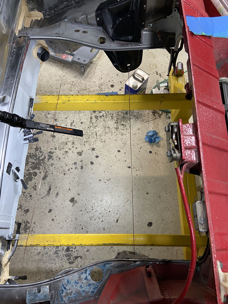 The second was used to measure from the bobbin to the leading edge of the suspension console ear though hole that the trailing arm pivot shaft goes though. Starting with the Driver side, I got the same measurement as Jeff Hail had (28 1/8" + 1/8" for the bobbin) ==> 28 1/4". This is the same as I measured several years back when I first started this project. 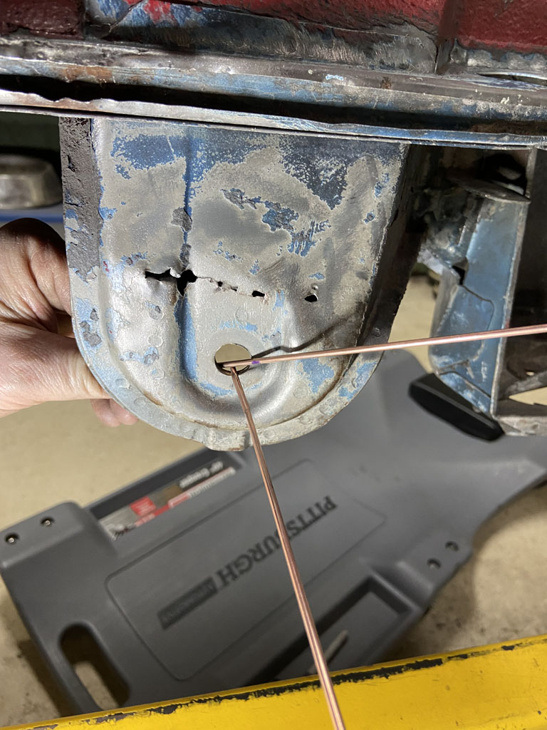 Then moved the console around until I duplicated the same measurements on the passenger side. 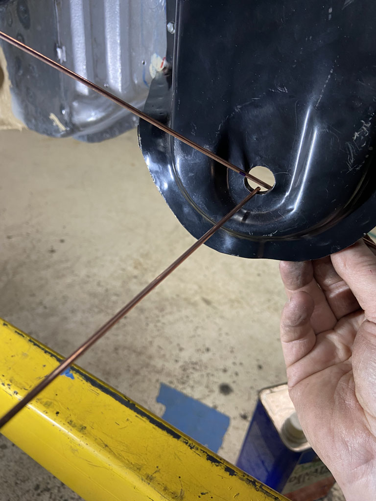 Then some double checks: 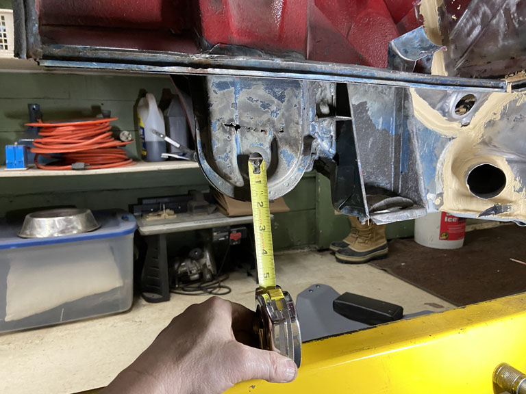 vs. 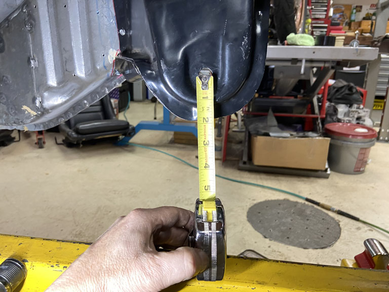 Then mocked up the engine compartment shelf and verified its position 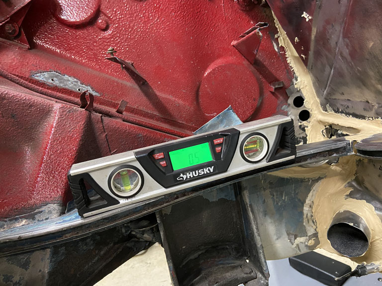 vs. 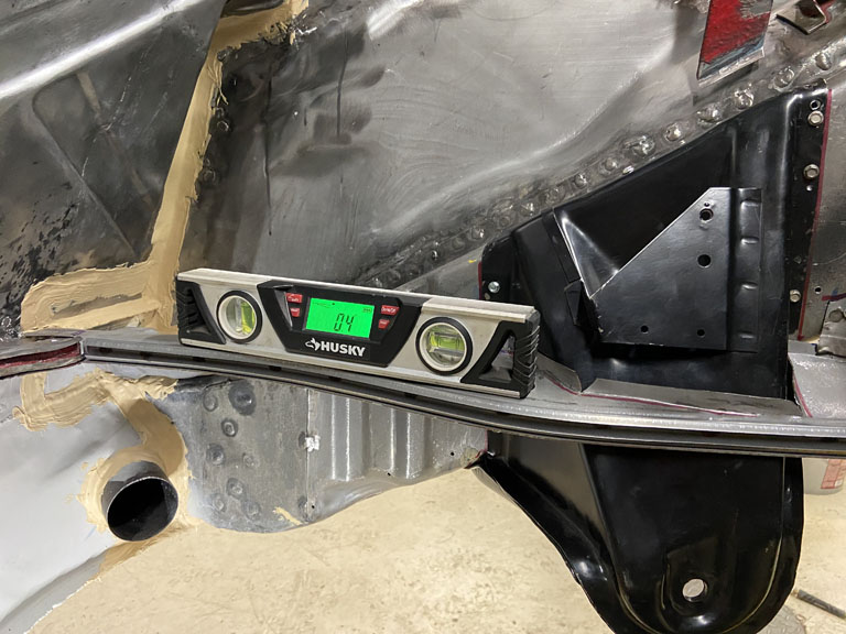 And then a quick check of overall shelf height. 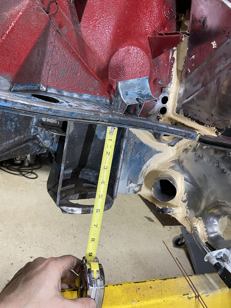 vs. 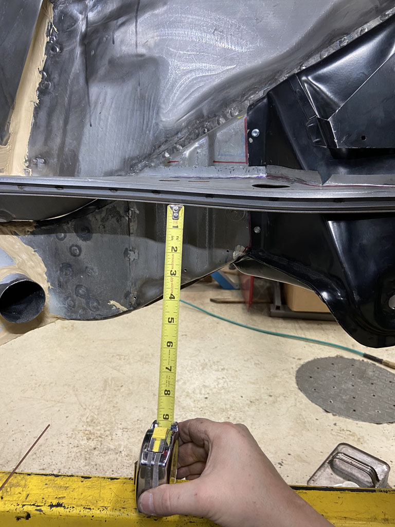 Took about 5 hours to get all this set up to my satisfaction. Can't wait to get around to getting this tack welded into position and then get the trailing arms mocked up! |
|
|
|
| Superhawk996 |
Dec 23 2021, 05:39 PM
Post
#464
|
|
914 Guru Group: Members Posts: 7,840 Joined: 25-August 18 From: Woods of N. Idaho Member No.: 22,428 Region Association: Galt's Gulch |
Front Control Arms
As a side project I knocked out the install of the Elephant Racing rubber front control arm bushings. 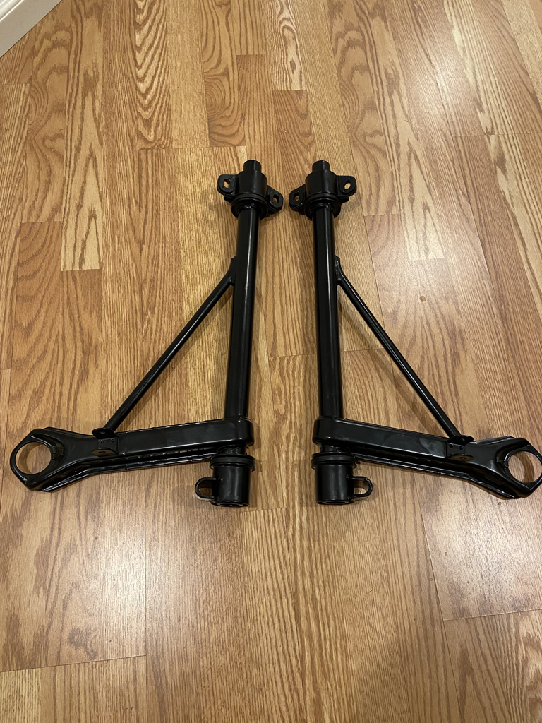 Very straight forward using their install tool and instructions. No drama on the install. (IMG:style_emoticons/default/biggrin.gif) The only glitch is that I had the rear bushing retainers powder coated. Really should have simply re-plated them. The powder coating adds too much thickness to the outer diameter of the retainer for these to slip back into the front crossmember properly. (IMG:style_emoticons/default/headbang.gif) Argh! Nothing a little bit of work with a flap wheel won't fix but it will be a PITA. Learn from my mistake. Plate them - don't powdercoat! (IMG:style_emoticons/default/happy11.gif) |
|
|
|
| Jett |
Dec 23 2021, 06:06 PM
Post
#465
|
|
Senior Member Group: Members Posts: 1,699 Joined: 27-July 14 From: Seattle Member No.: 17,686 Region Association: Pacific Northwest |
Great job! Very inspiring (IMG:style_emoticons/default/smile.gif)
|
|
|
|
| Superhawk996 |
Dec 29 2021, 10:46 AM
Post
#466
|
|
914 Guru Group: Members Posts: 7,840 Joined: 25-August 18 From: Woods of N. Idaho Member No.: 22,428 Region Association: Galt's Gulch |
Forging Ahead:
Suspension console tacked welded in 5 places. Time to start measuring before final welding. Started with a comparison to last know measurements. 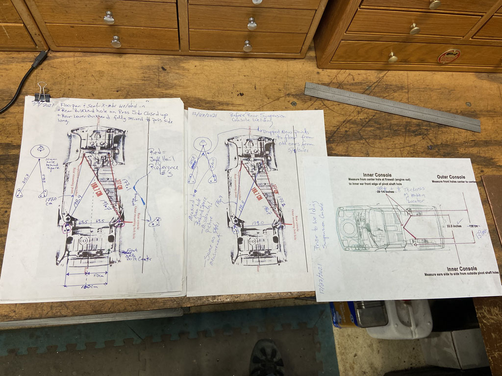 Then installed the Semi Trailing Arms (STA's) into a horizontal position for a baseline reference. Digital level at 0 degrees - measured at inside of STA right along the upper weld seam. 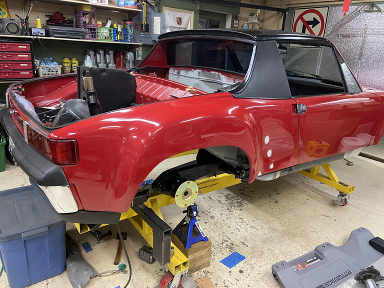 First check was of the driver side camber without shims which came in right at 89.9 degrees. This measurement will serve as baseline for comparison to the passenger side to be welded in. 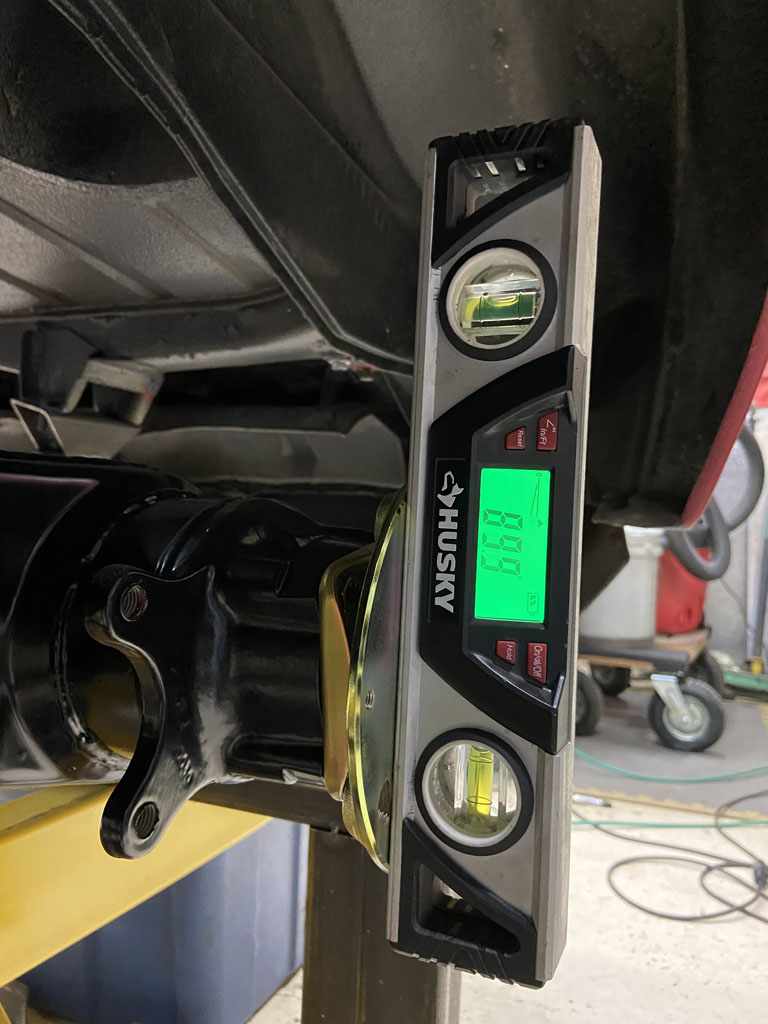 **Remember, no load on the car, and no deflection of the STA's so don't expect negative camber at this point in the game. Also remember that the STA's gain camber as they move into compression. I've arbitrarily chosen STA at horizontal as the baseline. I wish I had taken a ride height measurement between the hub center and the fender lip before I started long ago. (IMG:style_emoticons/default/headbang.gif) If anyone has a car sitting on a 4 post hoist it would be swell if you could throw a digital level on the STA (inside along the weld seam) and let me know what angle the STA is at under normal ride height. Passenger side came in at 89.4 degrees . This is not quite right as compared to driver side baseline. 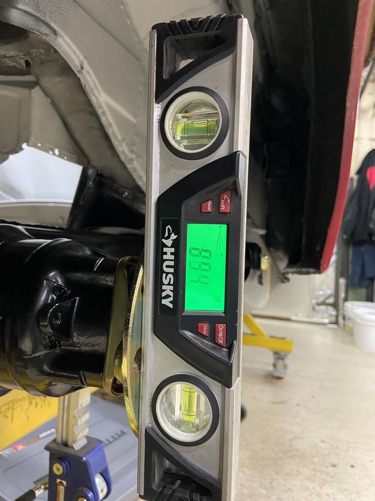 However, recall that during install of my outer suspension console, it ended up 5mm Higher in Z height than where it should be due to unplanned weld shrinkage. Not ideal but I knew I'd potentially have to add 5mm of "extra" shim to this side passenger side shim stack to compensate. Per the Peter Russek repair guide, 1mm of shim = 10 minutes of arc = 0.16 degrees. So if I have the outer approximately 4-5mm high in Z, that should mean that the passenger side would have 0.64 - 0.8 degrees negative camber MORE than the driver side. I'll take it. A little extra negative camber isn't a bad thing. As previously stated I can shim it out. However, since the math doens't line up perfectly, I need to go back and do a better measument of the outer suspension console in Z height to see if I can reconcile the disconnect between 0.64-0.8 predicted camber gain vs. the 0.5 degrees I see. Could be realted to my approximate 4-5mm measuremnt, or just be in the variance of my El Cheapo Husky brand digital level. Onward. Needed to verify that the wheelbase is the same between driver and passenger side. This was done with a body trammel. I measured from the hole for the front Anti Roll Bar to the center of the rear hub. 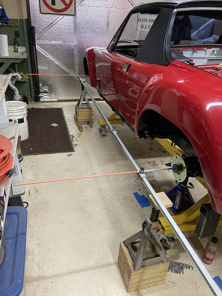 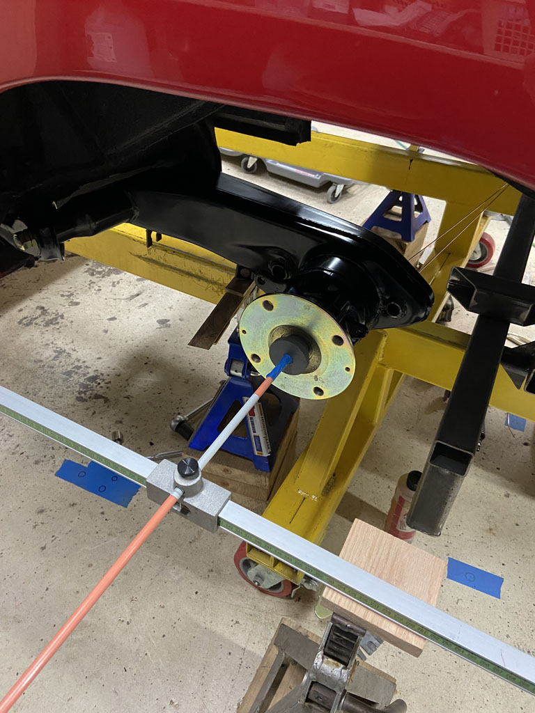 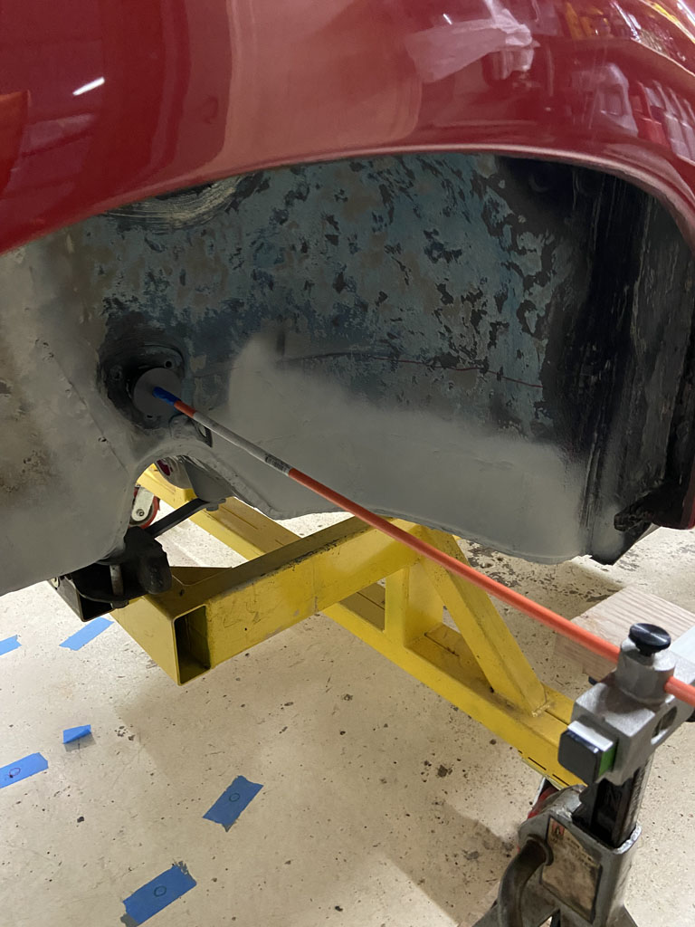 Without disturbing the trammel, I then flipped over to the driver side. 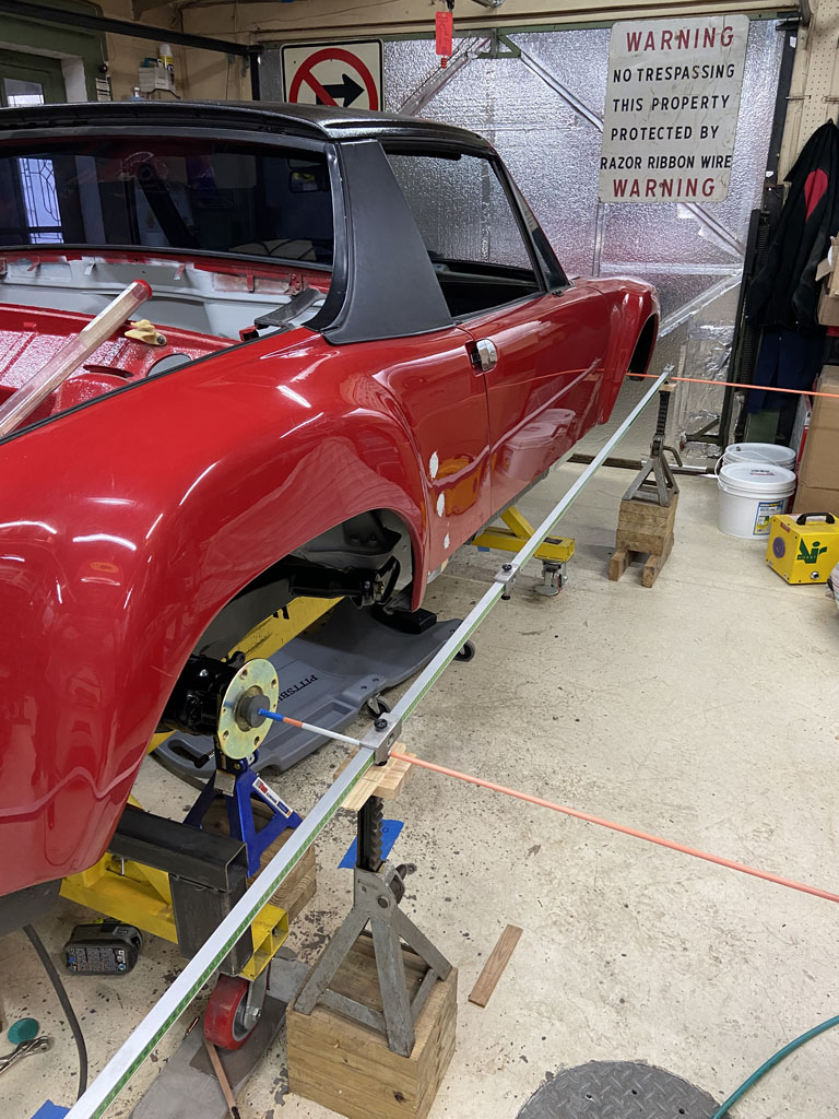 Success! (IMG:style_emoticons/default/piratenanner.gif) Fits perfectly. Just in case it helps anyone in the future that reference measurement is 238cm. 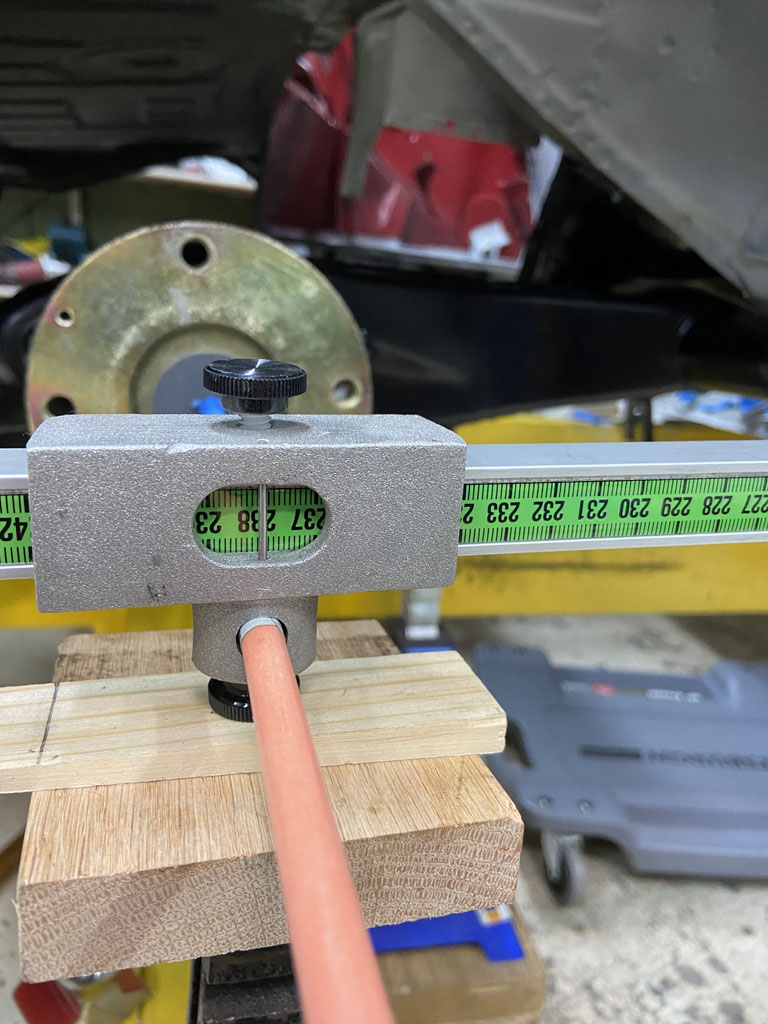 Then moved on to some quick body offset checks -- these are only approximate but wanted to make sure nothing was way out of place with the lateral location of the passenger side STA. Driver side measured from tram bar to sheemetal in front of door 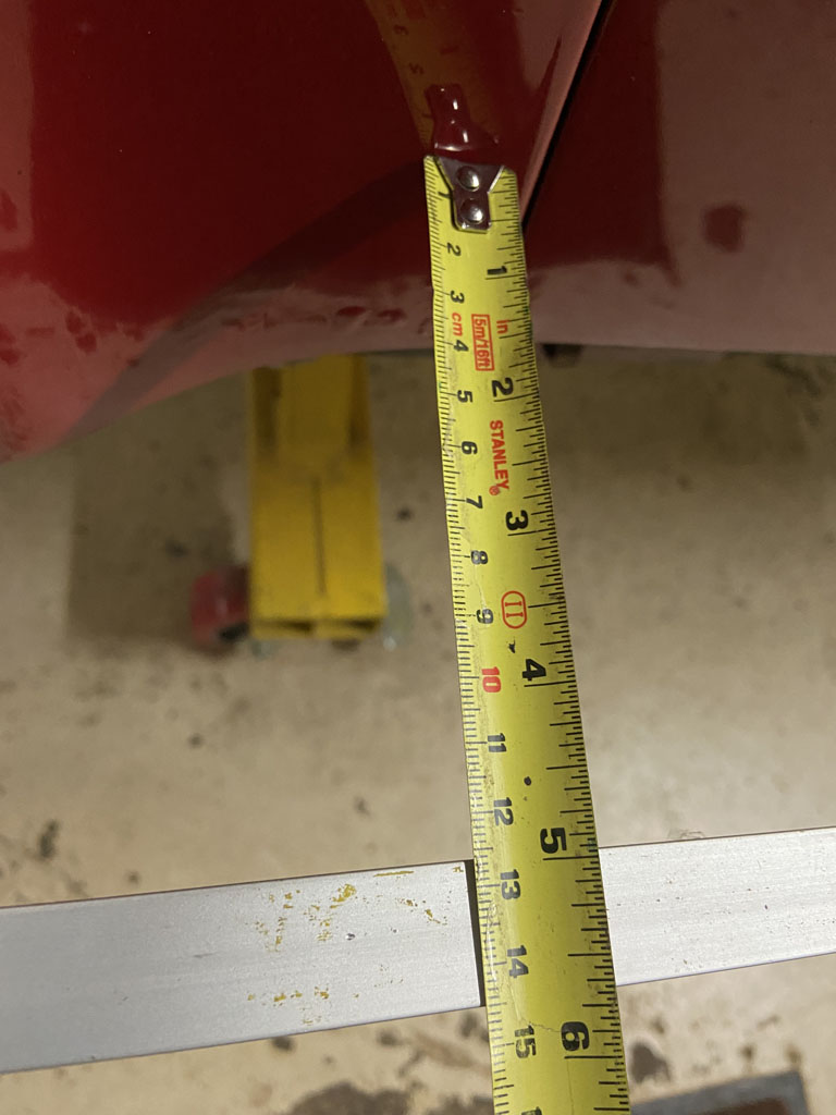 And again at rear of door. 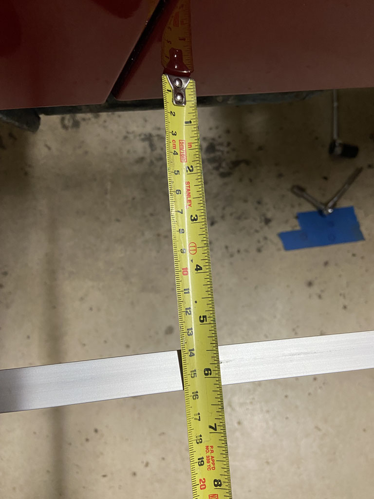 Repeated on passenger side front of door. 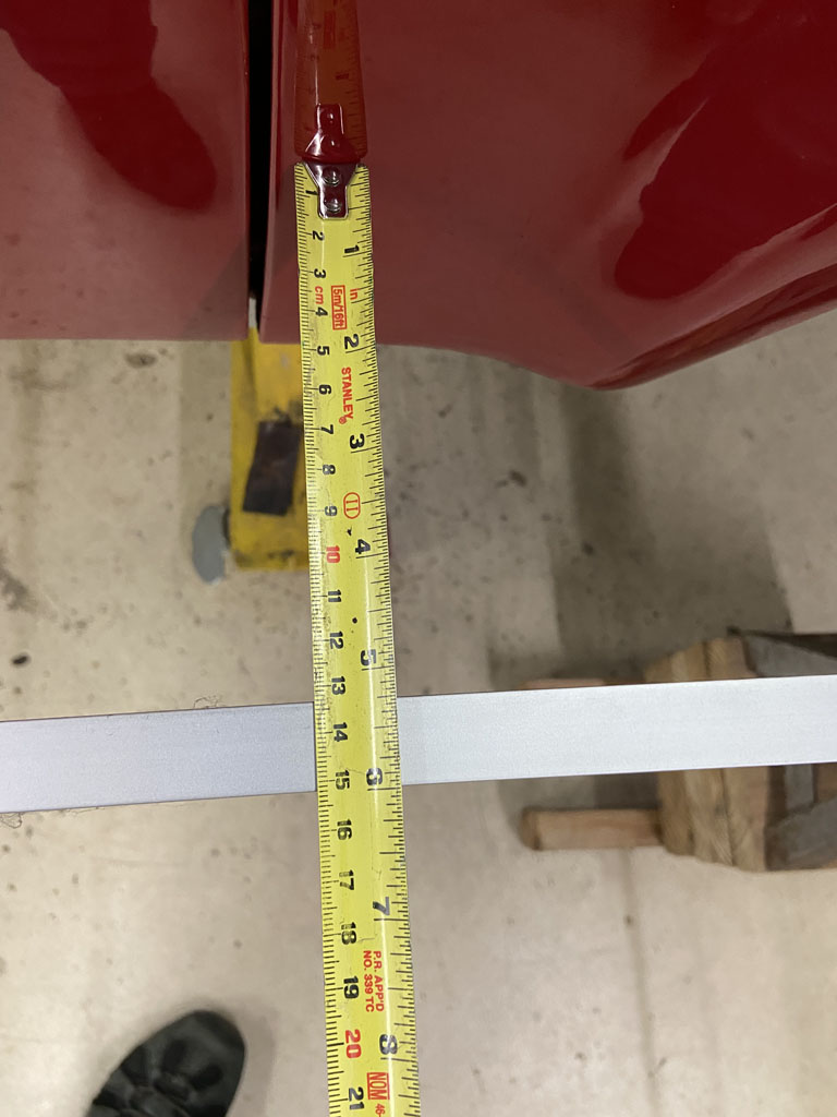 And passenger side rear of door 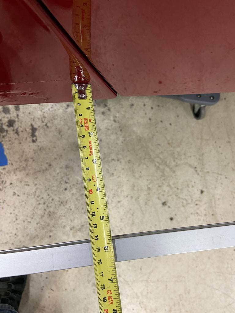 Not terrible. Overall about 6-7mm variance side to side. I don't think 6mm or 1/4" body variance of fender panels is out of the question in how outer sheetmetal attaches to the underbody structure and measurements that I've been so carefully been keeping track of. Again, need to check this more carefully. I need to get front LCA's installed and then want to check track width at front compared to rear. Project for tomorrow. |
|
|
|
| 930cabman |
Dec 29 2021, 05:16 PM
Post
#467
|
|
Advanced Member Group: Members Posts: 4,663 Joined: 12-November 20 From: Buffalo Member No.: 24,877 Region Association: North East States |
It's all numbers, but if not close to 100% it's wrong. Thank you for documenting this process, I will be fitting 4 new rear consoles at some point this winter and will refer to your process for sure.
|
|
|
|
| jesse7flying |
Dec 30 2021, 12:02 PM
Post
#468
|
|
Member Group: Members Posts: 139 Joined: 9-August 16 From: Burleson,TX Member No.: 20,281 Region Association: None |
Really nice work! I will certainly apply your lessons learned to my project.
|
 |
|
| 930cabman |
Dec 30 2021, 02:25 PM
Post
#469
|
|
Advanced Member Group: Members Posts: 4,663 Joined: 12-November 20 From: Buffalo Member No.: 24,877 Region Association: North East States |
I am not by any stretch a computer guy, but the information being shared on 914World is probably the best of ANY other forum. As always some guys don't know their A%# from their elbow, but mostly this is invaluable stuff.
Thanks for posting Phil and Bob and Brent and ................................... Happy New Year to all |
|
|
|
| Superhawk996 |
Jan 1 2022, 11:21 AM
Post
#470
|
|
914 Guru Group: Members Posts: 7,840 Joined: 25-August 18 From: Woods of N. Idaho Member No.: 22,428 Region Association: Galt's Gulch |
Checking Track Width, Wheelbase:
Dug out my front control arms and built them up with new Lemforder ball joints. 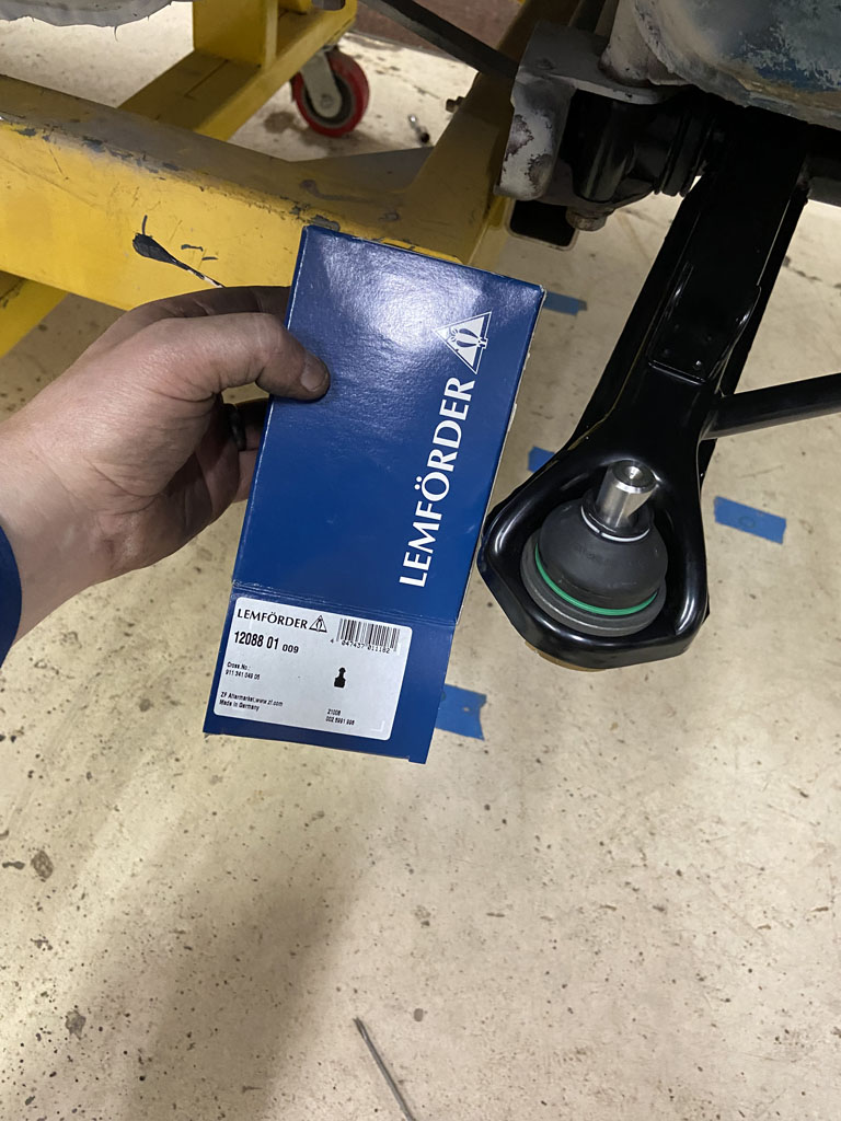 Added some new Boge inserts into the struts 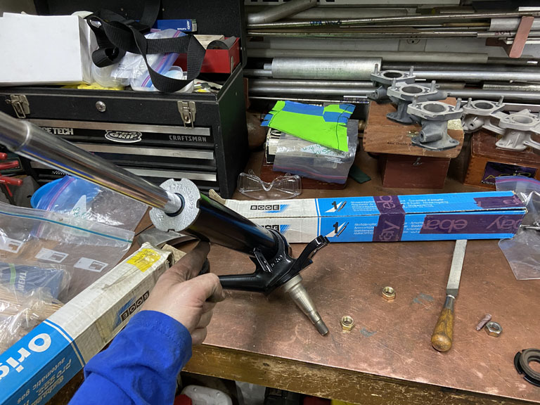 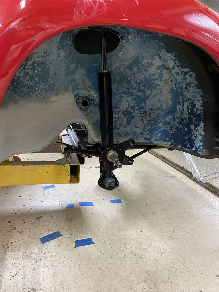 And we are off to the races to being able to measure track and wheel base directly after adding the front hub/rotor. To measure front track, it is given at curb height. The suspension as installed ends up in rebound. Therefore, the front suspension needed to be jacked up near curb height to get a decent measurement. Front track is listed as 1343mm with 5 1/2 x 15" wheels. But, in order to measure track off the rotor surface, we neeed to know the wheel offset. A bit of digging on the internet and PET shows the 5 1/2 x 15" wheel has an offset of 40mm. So let's roll. Jacked up to near curb height. 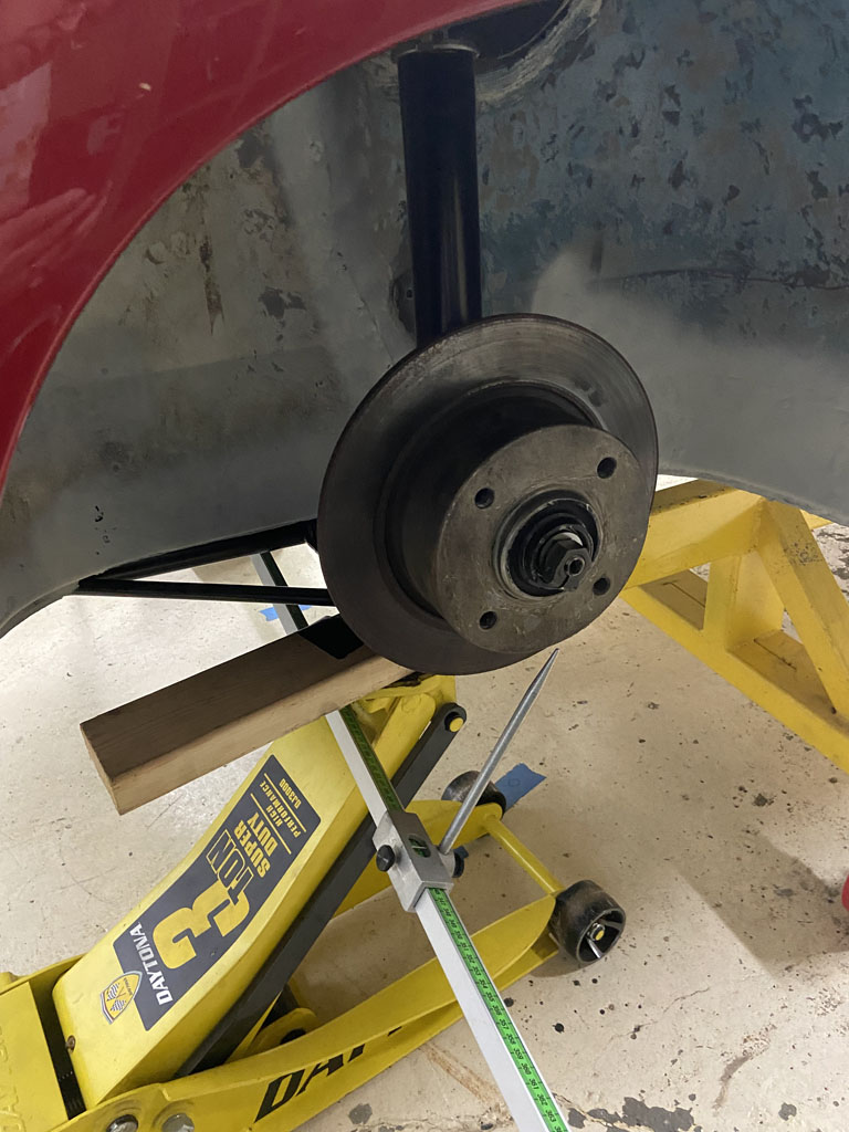 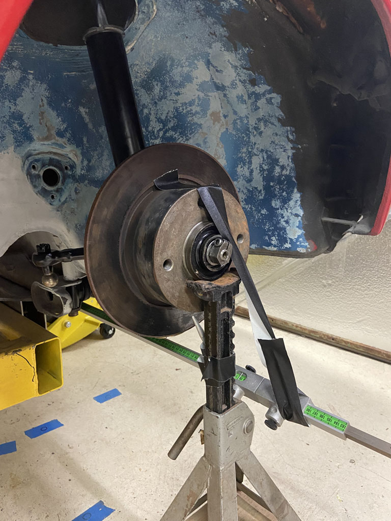 Direct measurement off the trammel is 1420mm. But remember, offset needs to accounted for to get track at the centerline of the wheel and tire. So 1420mm - (40mm offset x 2) = 1340mm (IMG:style_emoticons/default/piratenanner.gif) Looking good. Next up rear track is listed as 1383mm with the 5 1/2" wheel. Trammel measurement from rear rotor face to rear rotor face came up 1464mm. Again accounting for offset 1464mm - 80mm = 1384mm. Time to throw on some wheel & tires to see how things look. Driver Side wheel to the sheetmetal fender flange that the rocker panel sits into. 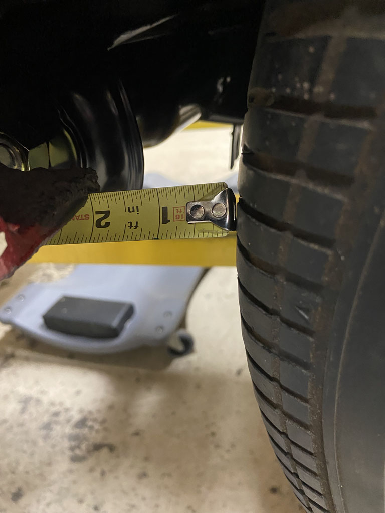 and comparing to passenger side 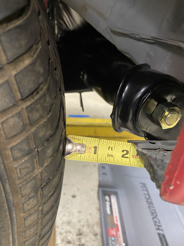 (IMG:style_emoticons/default/piratenanner.gif) Right on! (IMG:style_emoticons/default/wub.gif) Let's check the wheelbase. Wheel base is listed as 2450mm. 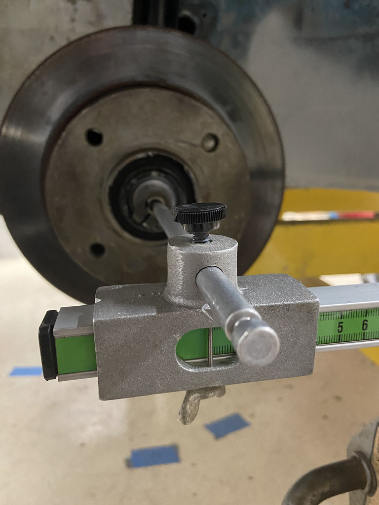 Driver side right on the money! 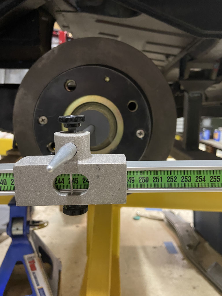 Passenger side: 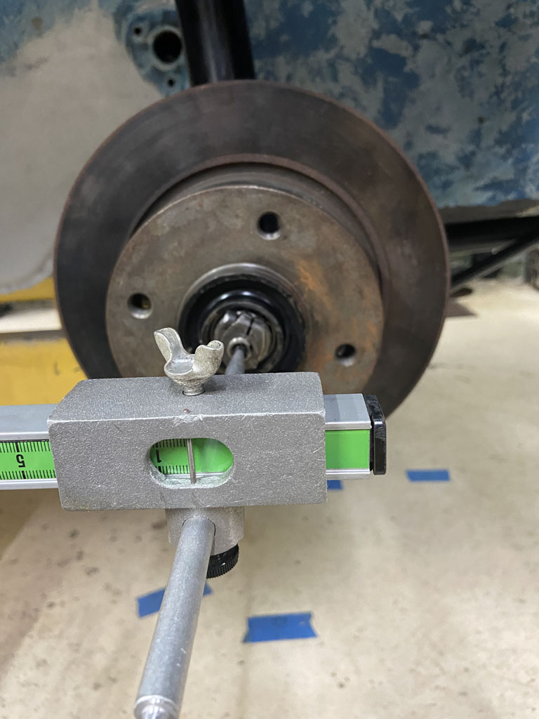 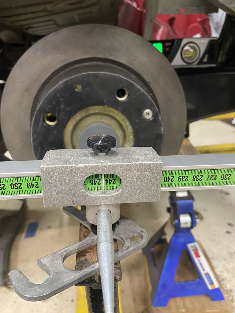 So here we have 2445mm. Looks like about 5mm different than passenger side. But, there is no need to panic. Remember that both sides measured the same from front ARB hole to rear hub centeline. I trust this measurement way more since there is only one degree of freedom (where the STA is) vs this direct wheelbase measurement that has two degress of freedom (STA location + position of the front strut spindle). Even if there were a full 5mm of variance in wheelbase between driver and passenger side, I could live with that but the reality is that wheel base will vary slightly side to side as we do the final alignment to set rear toe-in. So as a final reality check, I did move the rear wheels between maximum toe in and toe out doing a crude check from tire center line to centerline with a tap measure. Looks like I can get a maximum toe in 7/16" and maximum toe out of 1/4". As an engineer I love symetry but in this case, we would never want toe out so I'll live with it. (IMG:style_emoticons/default/rolleyes.gif) And finally, I wanted to take a rough look at camber gain. Before doing that recall, that I started out with a smidge more camber on the passenger side due to weld shrink when I put in the outer suspension console. I went back and shimmed passenger side until I had the same 89.9 degrees on the rear hub. That took 4.3mm of shim. So that answers my previous doubt about how much higer in Z the outer console was. Not terrible. I would have rather been right on the money but I can live with having to have an "extra" 4.3 mm of shim on the passenger side. So the math does work out (roughly). Per the Russek notes, 1mm of shim = 10' of camber = 0.16 degrees. So knowing that I'm 4.3mm high in Z, I should have an extra 0.68 degrees of camber on the passenger side. I had 0.5 degrees more. I'll chalk the other 0.18 degrees of error up to build variation, measurement error, and accuracy limitation & repeatability of my Husky angle gauge. I then pushed the rear STA's up to a point where I thought they looked like they were closer to curb height. I then took a quick look at camber gained. 2 degrees on Driver Side 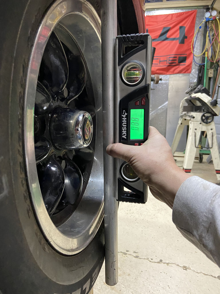 2.2 degrees on Passenger Side. 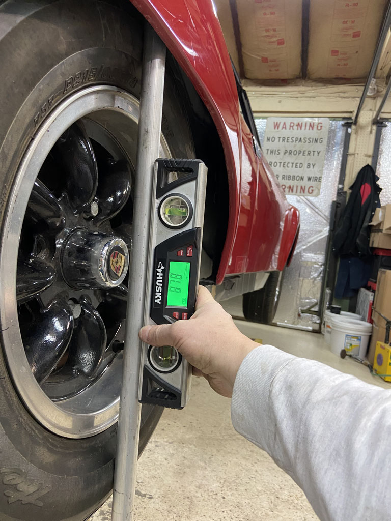 Loving it. (IMG:style_emoticons/default/shades.gif) So at this point, we've verified that camber gain is working properly (increasing as wheel goes into compression), that it is pretty close to symetrical side to side, and that near curb height we have more than enough camber. We would then add shims to take camber out closer to spec at curb. Feeling really good about proceeding with final welding of the inner suspension console today. (IMG:style_emoticons/default/welder.gif) |
|
|
|
| Superhawk996 |
Jan 3 2022, 05:15 PM
Post
#471
|
|
914 Guru Group: Members Posts: 7,840 Joined: 25-August 18 From: Woods of N. Idaho Member No.: 22,428 Region Association: Galt's Gulch |
Well, I'm comitted now:
  As usual there was a catch. Why I didn't remove the old remnant of the "bow tie" from the outer suspension console when it was on the bench is beyond me. (IMG:style_emoticons/default/screwy.gif) Oh well much more fun to work on it upside down under the car. (IMG:style_emoticons/default/headbang.gif) 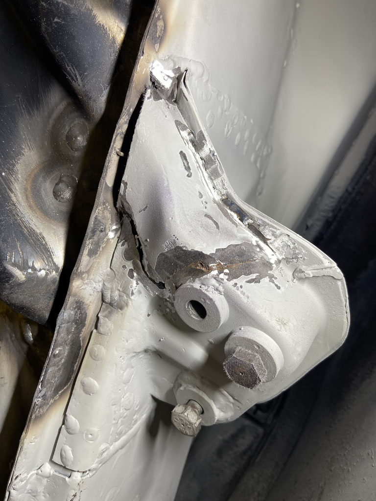 When I finally got it removed, I was impressed to find the black Eastwood Frame Coating and rust converter was still in between the sheetmetal layers and had held up well to all the welding that was done while installing the outer suspension console. 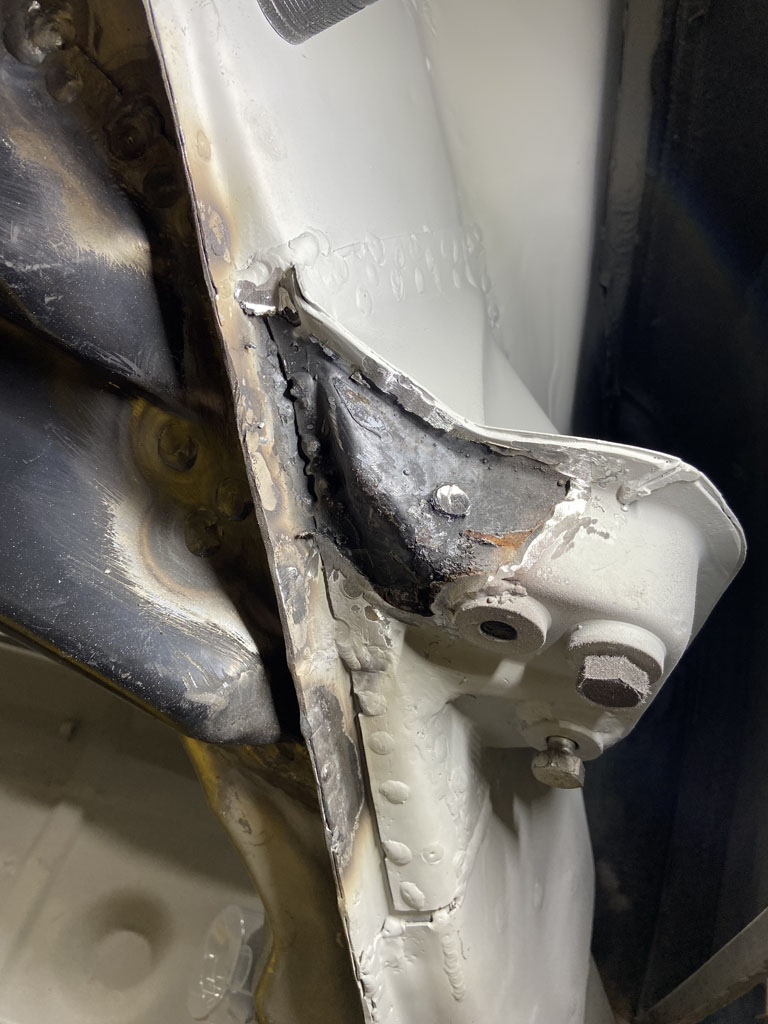 Although I had wanted to button on up and have the bow ties welded in place by end of last night. It just wasn't in the cards. OEM remnant piece I measured was 2.0mm thick (0.080"). These laser cut parts are 0.100". Very tough to form. The two piece bow tie that is mocked up and spot welded is easy. The one piece part is much tougher. I've bent it about as close as my little 6" vice mounted press brake will get it. Going to have to break out the serious heat to finish forming it. 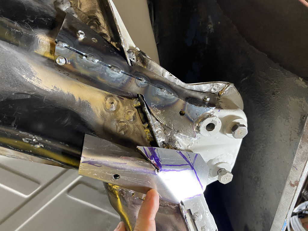 These pieces are way better than having to start from scratch, create templates, source the material, and then cut them out with a band saw. Many thanks to Cary (RIP) for designing them, 914Rubber @Mikey914 for making them, and @Mepstein for donating these to me. As a plea for the future: Sure would be great to have the parts made from 0.080" material - don't need the extra weight of 0.100" thick material Sure would be great to have these pre-stamped into the proper shape. I'd glady have paid some decent money to not be fiddling with forming these from flat sheet stock. @peteyd |
|
|
|
| Mikey914 |
Jan 4 2022, 12:07 AM
Post
#472
|
|
The rubber man Group: Members Posts: 12,782 Joined: 27-December 04 From: Hillsboro, OR Member No.: 3,348 Region Association: None |
QUOTE(Superhawk996 @ Jan 3 2022, 04:15 PM)  Well, I'm comitted now: As usual there was a catch. Why I didn't remove the old remnant of the "bow tie" from the outer suspension console when it was on the bench is beyond me. (IMG:style_emoticons/default/screwy.gif) Oh well much more fun to work on it upside down under the car. (IMG:style_emoticons/default/headbang.gif) When I finally got it removed, I was impressed to find the black Eastwood Frame Coating and rust converter was still in between the sheetmetal layers and had held up well to all the welding that was done while installing the outer suspension console. Although I had wanted to button on up and have the bow ties welded in place by end of last night. It just wasn't in the cards. OEM remnant piece I measured was 2.0mm thick (0.080"). These laser cut parts are 0.100". Very tough to form. The two piece bow tie that is mocked up and spot welded is easy. The one piece part is much tougher. I've bent it about as close as my little 6" vice mounted press brake will get it. Going to have to break out the serious heat to finish forming it. These pieces are way better than having to start from scratch, create templates, source the material, and then cut them out with a band saw. Many thanks to Cary (RIP) for designing them, 914Rubber @Mikey914 for making them, and @Mepstein for donating these to me. As a plea for the future: Sure would be great to have the parts made from 0.080" material - don't need the extra weight of 0.100" thick material Sure would be great to have these pre-stamped into the proper shape. I'd glady have paid some decent money to not be fiddling with forming these from flat sheet stock. @peteyd Pretty sure I can form these to be easy to install. Next run when we drop down.080 it will be easier. Mark |
|
|
|
| peteyd |
Jan 4 2022, 09:25 AM
Post
#473
|
|
Senior Member Group: Members Posts: 743 Joined: 27-March 08 From: Elora, Ontario, Canada Member No.: 8,858 Region Association: Canada |
QUOTE(Superhawk996 @ Jan 3 2022, 03:15 PM) As a plea for the future: Sure would be great to have the parts made from 0.080" material - don't need the extra weight of 0.100" thick material Sure would be great to have these pre-stamped into the proper shape. I'd glady have paid some decent money to not be fiddling with forming these from flat sheet stock. @peteyd I would have measured the originals that we scanned and made the tooling with the correct clearances to match the originals. When we get back to this tooling, we will definitely be making them to the same thickness as Porsche did. Pete |
|
|
|
| Superhawk996 |
Jan 13 2022, 08:05 AM
Post
#474
|
|
914 Guru Group: Members Posts: 7,840 Joined: 25-August 18 From: Woods of N. Idaho Member No.: 22,428 Region Association: Galt's Gulch |
Suspension console is nearly complete.
Finished welding in the "bow tie" console reinforcements that tie the outer console to the inner. Yeah, the welding sure isn't the stack of dimes look. It is so hard doing all the out of position welding. Much of it is overhead. Haven't quite come up with a good way to keep my arms raised for long periods of time without getting shaky. Guess I need to workout more! I drizzled a little Eastwood Frame coating down into the gaps to prevent rust between the steel layers. It is very thin and really does creep into gaps. Anyway sprayed some into the gaps until it came out in other places. 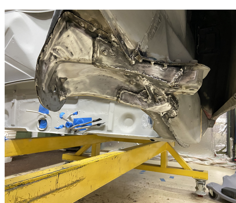 @TRS63 As a side note; mock up the suspension before final welding of the bow ties. I found that the outer console reinfocement was too long and the thickess of it was restricting range of toe-in adjustment. Had to trim the bow tie back about 3/8" so that it provided proper cleaance to the outer trailing arm pivot. Not a big deal but mock up of the trailing arm saved the day before I found this out too late at final assembly time. Then moved my attention to the install of the Tangerine Racing inner suspension console reinforcements. I purchased them pre-shaped which does speed things up a little bit. However, there is still fine tuning that needs to be done as these get welded in. 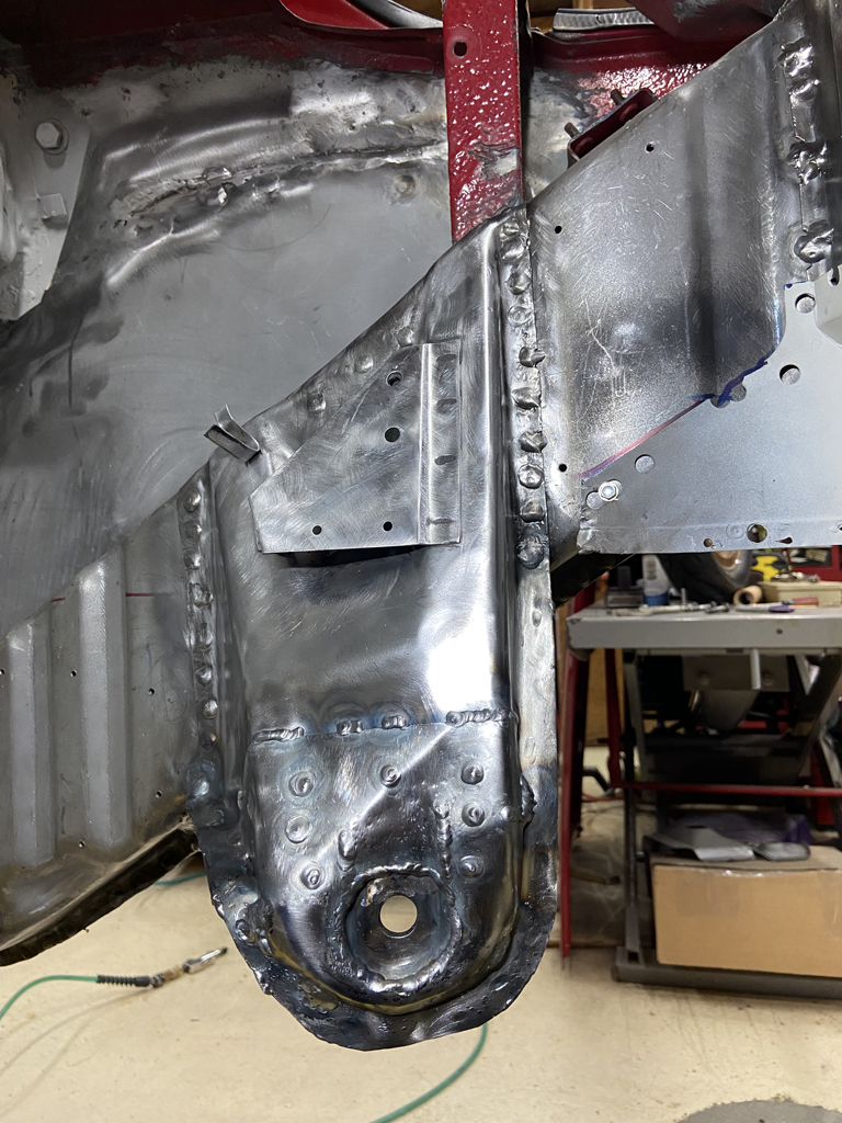 Still need to finish a couple perimeter welds on this and then repeat the Eastwood rust coating. Will then seal the perimeter with a little seam sealer. Will then shoot it with some 2K primer. One thing that I screwed up -- I should have sand blasted the suspension console before the installation. When welding on it I was constantly getting massive smoke as the paint inside the console burned away. Very annoying. Plus, now I'm thinking there is very little corrosion protection left inside the inner suspension console. I'm thining I'm going to drill a small hole about 5/32" just big enough to get the Eastwood spray tube in there and then reshoot the inside of the console with the rust inhibiting coating. Then weld up the 5/32" hole. Sure there will be some localized burn away in the vicinity of the hole, but I'm thinking that this still has to be better protection than what little must be left of the original paint. Live & learn! Next up: Repair the stress cracked Driver side inner suspension console and then put the other Tangerine stiffener over the driver side. |
|
|
|
| Cairo94507 |
Jan 13 2022, 09:39 AM
Post
#475
|
|
Michael Group: Members Posts: 10,634 Joined: 1-November 08 From: Auburn, CA Member No.: 9,712 Region Association: Northern California |
Amazing work. (IMG:style_emoticons/default/beerchug.gif)
|
|
|
|
| Superhawk996 |
Jan 14 2022, 08:15 AM
Post
#476
|
|
914 Guru Group: Members Posts: 7,840 Joined: 25-August 18 From: Woods of N. Idaho Member No.: 22,428 Region Association: Galt's Gulch |
Public Service Announcment
Keep your drain holes clean & clear to allow moisture to drain properly. The rear suspension consoles on 914's have always been prone to rust, stress cracking, and subsequent failure. Especially as loads increase from spirited driving, Autocross, and the worst case, racing with sticky tires. In the case of my chassis I suspect that it has about 160K miles on it. Stress cracking in this area wouldn't be surprising just with normal wear and tear. When I first started rustoration, I quickly found evidence of stress cracking on the driver side inner console ear. Initially this area looked fine and was covered with undercoating that seems to have been applied to so many of these cars over the years. Not sure if someone was trying to hide it, or maybe the metal was just thin already and they simply sprayed over it not even knowing. This is how it looked after cleaning off the undercoating with a wire flail wheel.  This stress cracking comes from 3 issues: 1) The stamping appears to be thinning in this area as the metal "flows" during pressing. When metal is stretched though the tight radius corners like this area has the material thins out. 2) This console ear bears lateral loads during corning leading to some higher material stress and cyclical fatigue. 3) Rust compromises the console from the inside out. It can look fine on the outside but be paper thin metal. In my case, I started by cutting out the stress cracked area and verifying that I got back to an area that has full thickness metal. 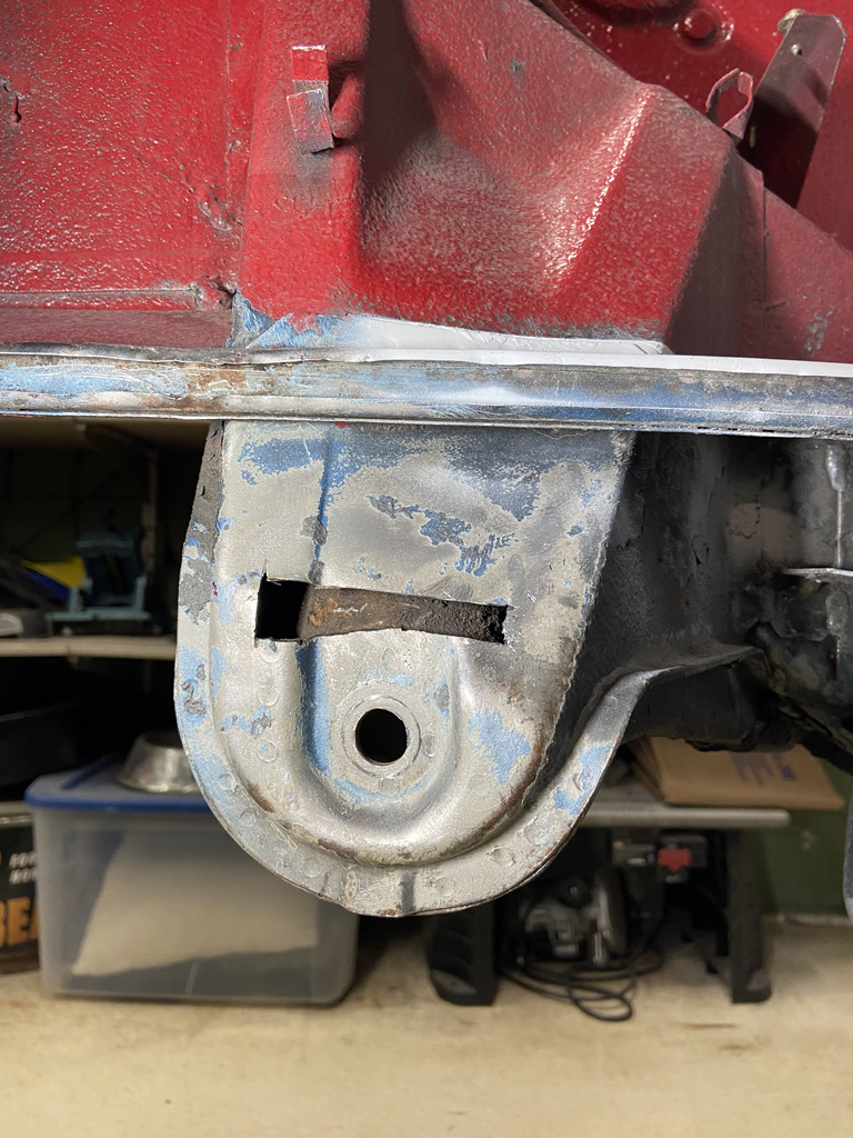 When I got the material cut out I made another upleaseant discovery. The ear is full of sand, rust particles, etc., and the drain hole is completely obstructed. You should be able to get a piece of 1/16" welding rod inserted up though the bottom drain to ensure its clear. No-go. 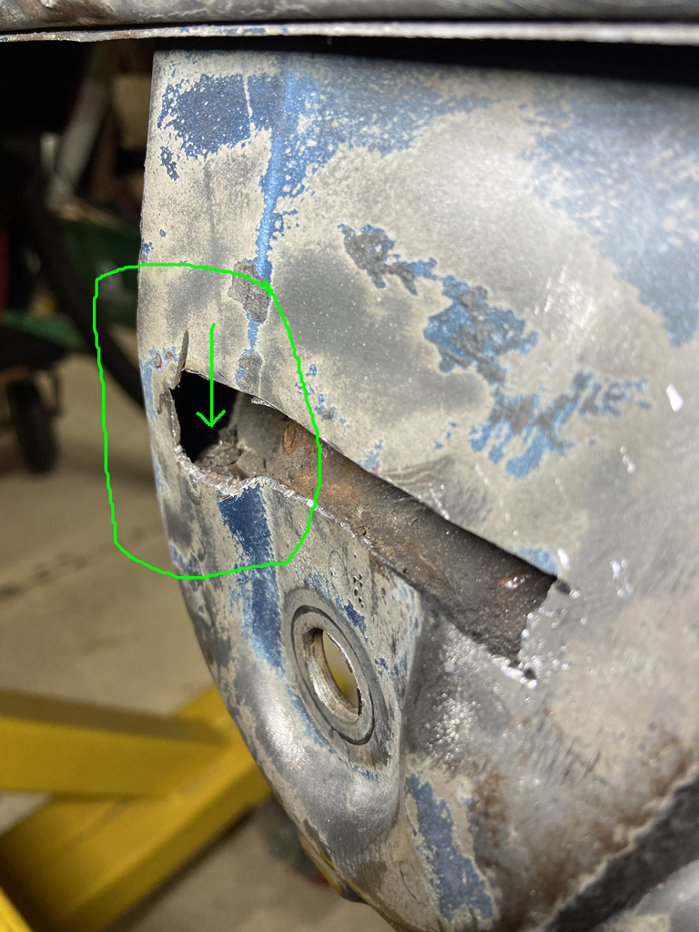 Getting my drain cleared proved to be really tough. Usually this can be done just by using a pick tool or wiggling the welding rod around and evenually the blockage can be cleared. When I got the drain hole clear with a heavy duty pick, I still couldn't get the welding rod to insert all the way up into the console. The stuff up in there was hard as cement and not budging. (IMG:style_emoticons/default/headbang.gif) (IMG:style_emoticons/default/confused24.gif) Time to get more agressive. Progressively started drilling 1/8" holes and using the pick and welding rod to break up the debris that was blocking the lower channel. From the picture below you get an idea of how it had to be broken up in little sections. 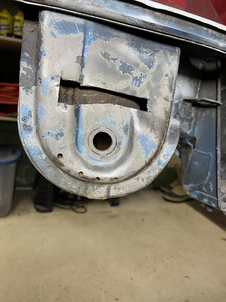 After about 90 minutes of fiddling around, I was able to get all the obstuction clear on both sides of the drain so that it will drain water freely. Moral of the story: Keep your drain holes cleared as part of annual maintenance. Not just these drains, do all of them including the longs. In my case, this wasn't a terribly big deal. I'll now have to weld up the holes in addition to fixing the stress cracked portion that originally started this job. At the end, it will get the Tangerine Racing reinfocement put over the whole area for some added strength. |
|
|
|
| Superhawk996 |
Jan 17 2022, 11:25 AM
Post
#477
|
|
914 Guru Group: Members Posts: 7,840 Joined: 25-August 18 From: Woods of N. Idaho Member No.: 22,428 Region Association: Galt's Gulch |
Driver side Console Repair Complete
Quick photos of repair to the inner console ear that was cracked. Fitted and tacked in new metal. 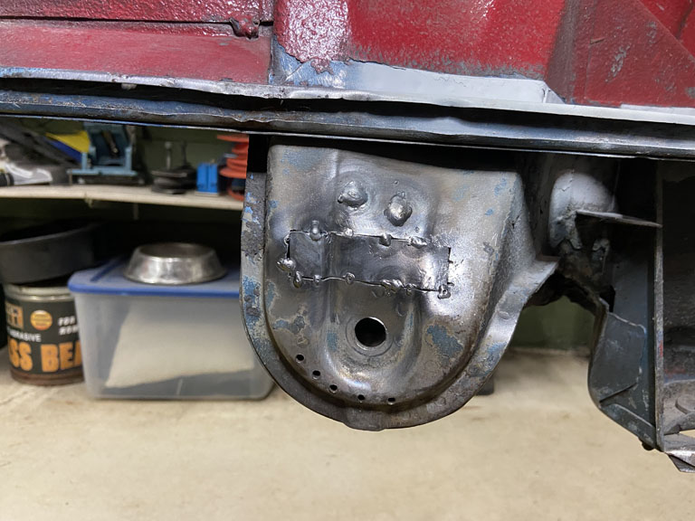 Welded it up. 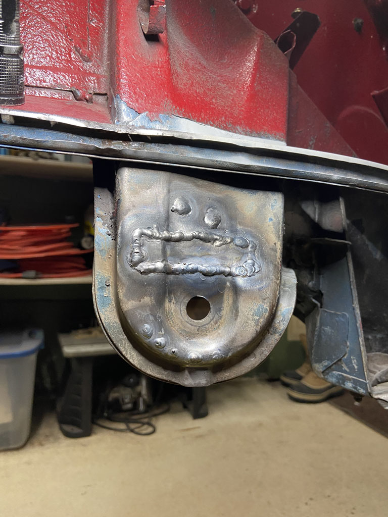 Ground down the weld beads a bit. Wish I could get the bead height just right. Every now and then I get the perfect combination of gap between metal, body position, and weld technique to lay in a bead that has 100% penetration but without excess bead. Puts a smile of my face. Just wish I could to it repeatedly at will even in out of postion welding. Have also come to the conclusion that I need to improve my left hand and out of postion welding skills. 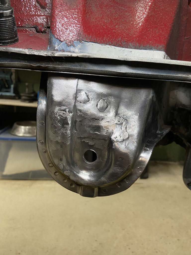 And finally put in the Tangerine Racing Stiffner. We are lucky to have vendors like Tangerine, 914Rubber, and others supporting us with niche parts like these that didn't exist last time I was working on 914's. 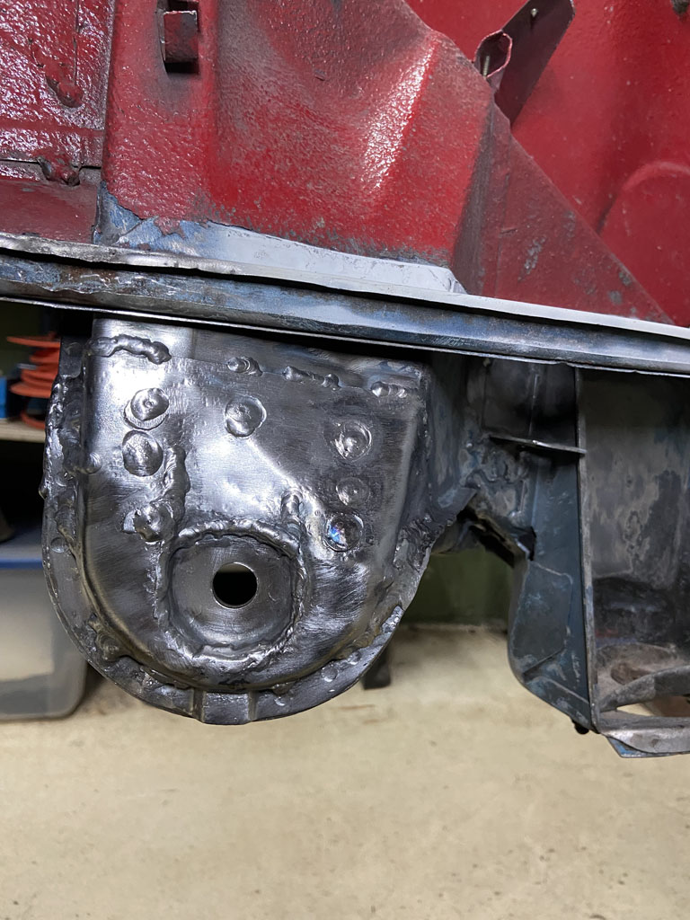 Stripped undercoat and paint off the rest of the driver side suspension console to ensure that there were no other cracks lurking on the driver side supspension console. Good to go! (IMG:style_emoticons/default/aktion035.gif) 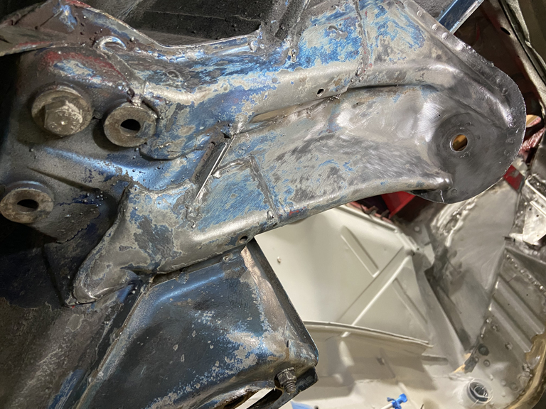 This has been such an odd car to work on. It was Florida car according to previous owner. So much of the metal is in almost pristine shape. Yet, the entire right side longitudinal was completely shot as was the entire floorpan. (IMG:style_emoticons/default/confused24.gif) Each time I see the wonderful Alaska Blue Metallic paint lurking below undercoating, I can't help but wonder what someone was thinking when they repainted the car red. (IMG:style_emoticons/default/barf.gif) Someday I'll get around to returning it to Alaska Blue Metallic but that won't be for a long time. Right now priority is to get this back to a rolling chasis. Next up: Get the right side engine mount and engine shelf installed. |
|
|
|
| Superhawk996 |
Jan 19 2022, 05:09 PM
Post
#478
|
|
914 Guru Group: Members Posts: 7,840 Joined: 25-August 18 From: Woods of N. Idaho Member No.: 22,428 Region Association: Galt's Gulch |
Engine Mount Install Underway.
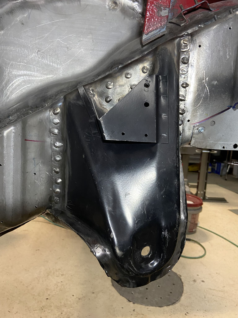
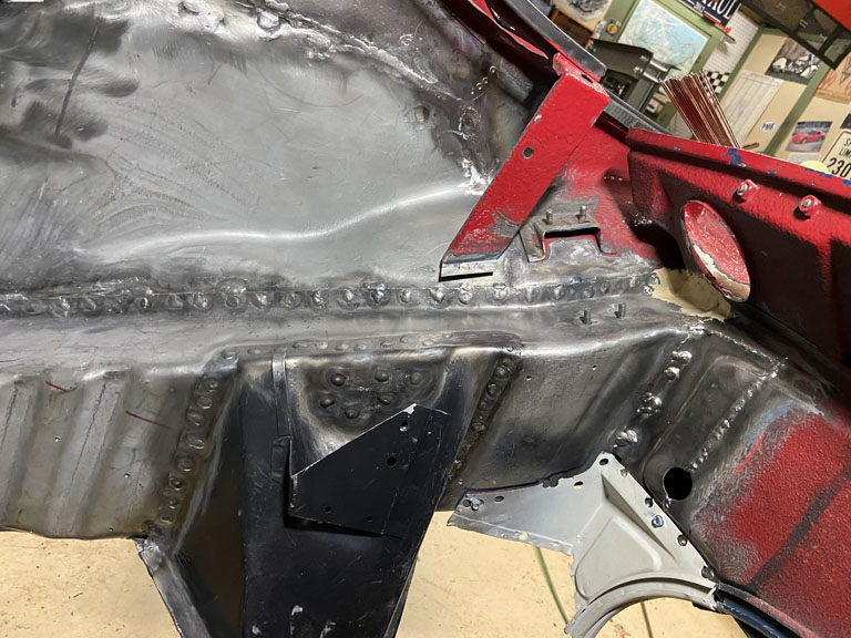
Started by cleaning it up and putting some Eastwood Frame Coating on the backside. 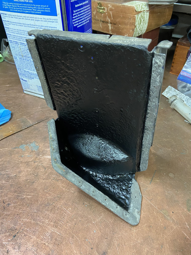 Now I'm a bit surprised no one has called me out on ditching the plan to double wrap that engine compartment longitudinal. The backstory is that I hate the corrugation on this part. It doesn't reproduce the original at all. Having said that I am grateful that it is available and that I didn't have to fabricate it from scratch. But the corrugation still pisses me off. (IMG:style_emoticons/default/happy11.gif) I really want the long to look as close to OEM as it can and the corrugations just won't do. In addition, the engineer in me can't stop thinking that lateral stiffness is compromised by the corrugated ribs. Yes, they add overall stiffness to the panel that is far better than flat sheet. Agree completely. The problem is the OEM has the corrugation ribs on the INSIDE and I don't have to look at them. I also think the nature of the 2 piece design with the corrugations on the inside yields a stiffer part since the corrugations are effectively closed off and bridged by the outer panel. If I wasn't so lazy, I'd do some CAE modeling and figure out if the single piece aftermarket piece (thicker single panel with corrugations) has the same overall stiffness as the OEM parts. (IMG:style_emoticons/default/screwy.gif) I'd rather be (IMG:style_emoticons/default/welder.gif) than do CAE on these parts. But couldn't let it go! To top that off, after developing the templates to do a wrap, I ended up with the cut steel in my hands and decided that was just too much weight to add for what might be too little gain in lateral stiffness. And as the final straw, when I was mocking up the rear suspension console, it just fit better to the corrugated long without the added thickness of the wrap. So here's what I did under the suspension console and what I've continued to do under the Engine mount to get a smooth long appearance and to gain a bit of stiffness. I closed out the corrugations. I used a doubled up 0.043" strip like this. 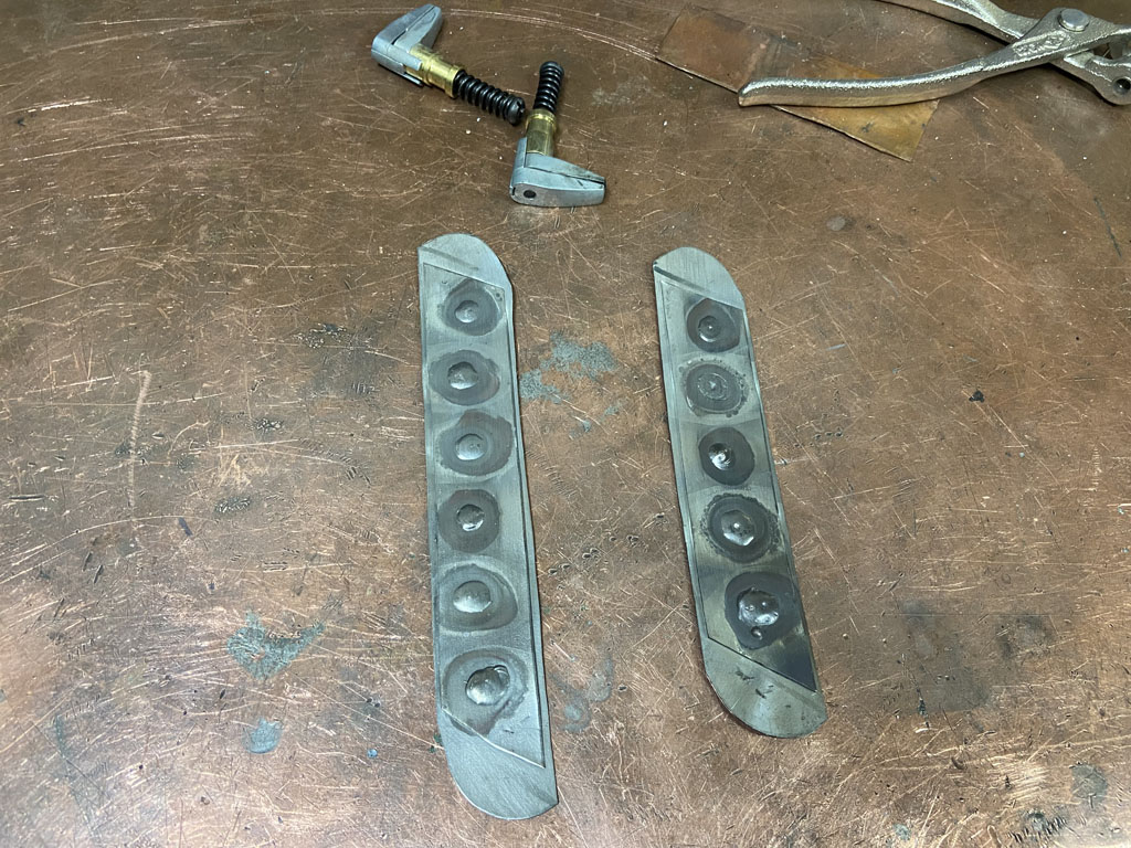 Here it is partially tacked into place and you get the idea of how it rolls over the upper and lower radius to close out the corrugation. 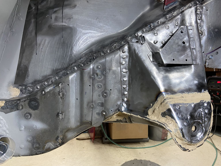 And of course, the weld beads need to be ground down to allow the engine mount to sit flat to the long. 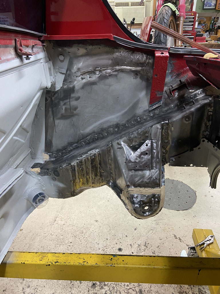 The main downside to this in my opinion is the time spent for an unquanified improvement. Well . . . at least I won't need to look at the corrugations that otherwise would have been apparent above the engine shelf! With a little luck, I'll get around to actually locating the engine mount and welding it in later this week. |
|
|
|
| Superhawk996 |
Jan 24 2022, 07:25 AM
Post
#479
|
|
914 Guru Group: Members Posts: 7,840 Joined: 25-August 18 From: Woods of N. Idaho Member No.: 22,428 Region Association: Galt's Gulch |
Engine Mount Done - Onward to to shelf install.
It's a good thing I don't do this work comercially. I constantly underestimate how much time it is going to take to get to the next step. Prep of parts is constantly underestimated. I'd be losing my (IMG:style_emoticons/default/bootyshake.gif) if I were estimating these tasks on a job cost basis. First the need to get the long coated (and dried) with some Eastwood Frame Coating so that there is some protection behind the engine mount. Then the need to drill the holes in the part for puddle welds. I would normally use a hand punch which is way quicker but the metal on the engine mount is too thick to use the hand punch. 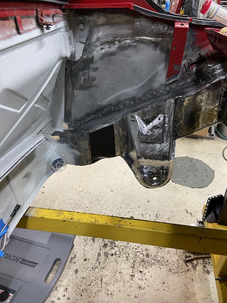 Then to do the basic mock-up work to make sure the part is properly located. In the case of the engine mount, you can't be too far off due to the dimple in the long but there is still a good 6mm of variation both fore and aft where the part could land and still "fit". 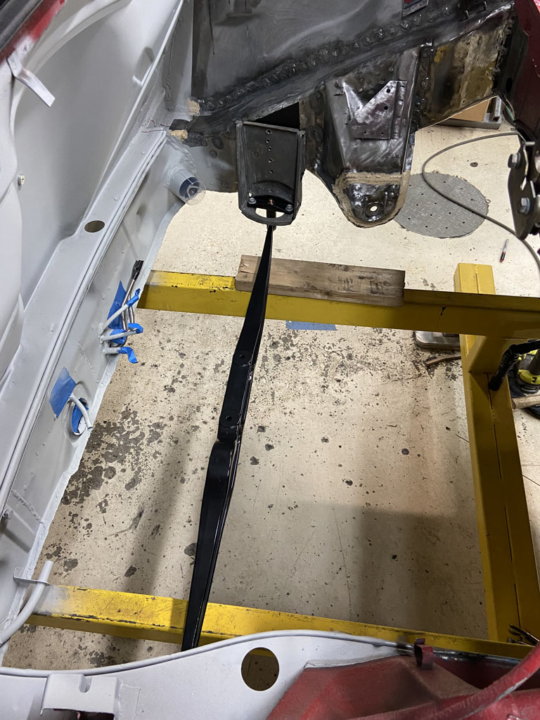 And then finally the welding time. There are three things here that take forever. First that I'm using TIG. It is a slower process than MIG for sure. Second, the need to keep things cool between welds so that I don't warp anything. Third, all welding is out of position including the puddle welds underneath the long being overhead welds. On this third point, I'm glad I'm not doing MIG which would be a PITA with it's showers of sparks. Doing this on a rotisserie would certainly be easier, but at this point, it doesn't make sense to stop to build a rotisserie to replace the body dolly that was needed for the the longitudinal and floor pan replacement work. Win some, lose some. I'm going to call the engine mount being done a win. 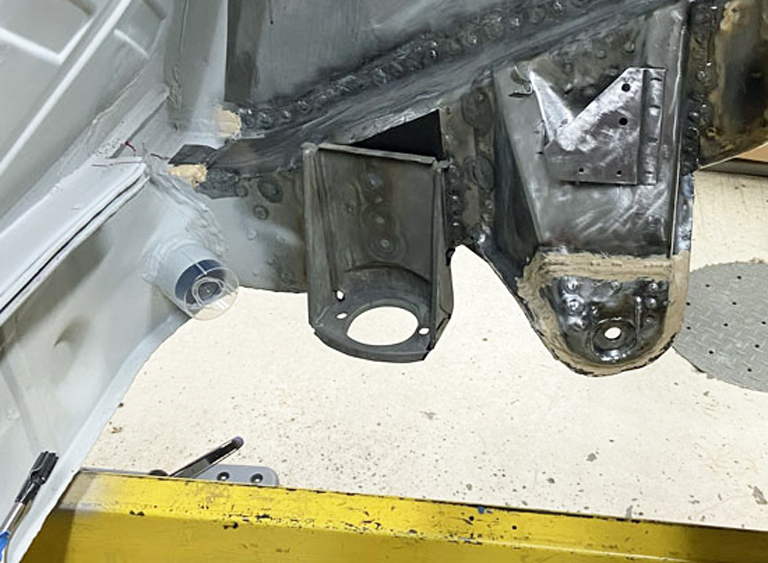 |
|
|
|
| Superhawk996 |
Jan 24 2022, 07:39 AM
Post
#480
|
|
914 Guru Group: Members Posts: 7,840 Joined: 25-August 18 From: Woods of N. Idaho Member No.: 22,428 Region Association: Galt's Gulch |
Other diversions
As I work toward getting a rolling chassis, I needed some new parts. PMB and 914Rubber to the rescue. 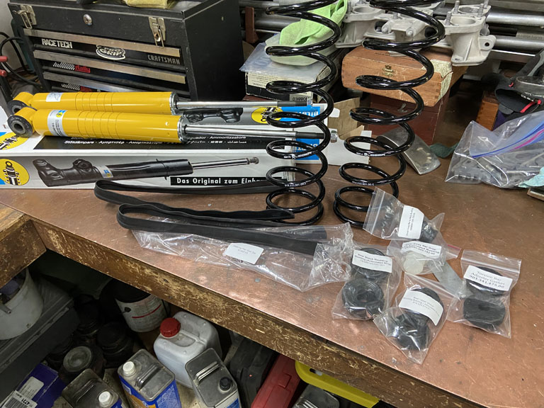 Vehicle came with KYB rear dampers and some sort of progressive spring. Those need to go bye bye. But I needed the spring top caps and associated hardware. 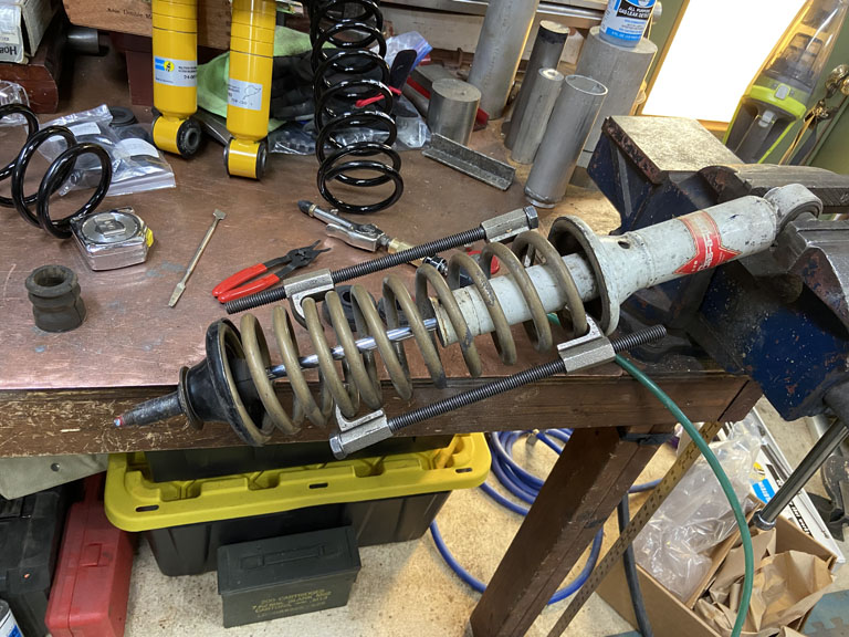 I did get a kick out of the sticker on the Bilstein's that say tested at Nurburgring Nordschleife. I'm not quite convinced these dampers were tested there though (IMG:style_emoticons/default/av-943.gif) I've done some lapping there long ago, maybe someday I'll get the chance to go back if the world comes to its senses. 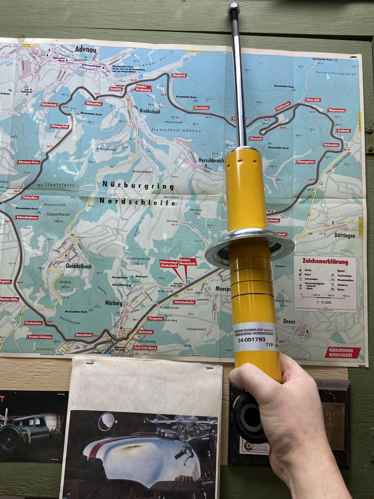 Being a bit OCD, I'm certainly going to have to find some yellow paint to put in that lowest groove so it doesn't rust in the first week it's exposed to the elements. Not sure why Bilstein chooses to put the clip in the lowest grove and then paint. Must be for low riders. |
|
|
|
|
1 User(s) are reading this topic (1 Guests and 0 Anonymous Users)
0 Members:

|
Lo-Fi Version | Time is now: 17th May 2026 - 09:21 AM |
Invision Power Board
v9.1.4 © 2026 IPS, Inc.