|
|
|
Porsche, and the Porsche crest are registered trademarks of Dr. Ing. h.c. F. Porsche AG.
This site is not affiliated with Porsche in any way. Its only purpose is to provide an online forum for car enthusiasts. All other trademarks are property of their respective owners. |
|
|

  |

| narino |
 Mar 27 2019, 10:26 PM Mar 27 2019, 10:26 PM
Post
#1
|
|
Member  Group: Members Posts: 231 Joined: 14-August 07 From: Los Angeles, CA Member No.: 8,001 Region Association: None |
With the warm weather I've spent the last few days fixing wire connections and removing extraneous wires by the PO. A couple wires have me stumped, hoping for some help from the hive mind.
#1 - I have a heavy gauge red wire that is coming off the alternator, that the previous owner spliced into and ran through the longs to the hot terminal by the fuse box.
#2 - The PO ran heavy gauge red wires through the longs to the hot terminal by the fuse box.
#3 - I bought some pilot fog lights and went to install them and saw my horns are in the way.
Once I get these hot wires figured out I'll feel safer trying to start her and get her back on the road. Thanks in advance! (IMG:http://narino.com/images/wire%20to%20alt%2001%20sm.jpg) (IMG:http://narino.com/images/wire%20to%20longs%2001%20sm.jpg) (IMG:http://narino.com/images/horns%20sm.jpg) |
   |

 
|
| Chi-town |
Mar 27 2019, 10:43 PM
Post
#2
|
|
Senior Member Group: Members Posts: 850 Joined: 31-August 18 From: Disneyland Member No.: 22,446 Region Association: Southern California |
Wires in the longs = not stock
Horns = not stock Sounds like the PO was trying to get around a wiring harness issue. |
|
|
|
| narino |
Mar 27 2019, 11:37 PM
Post
#3
|
|
Member Group: Members Posts: 231 Joined: 14-August 07 From: Los Angeles, CA Member No.: 8,001 Region Association: None |
Thanks for the reply Chi-town.
Any idea about the Alternator red wire? I have no idea where it's supposed to connect. Oddly, it looks like it's supposed to be there, the wire goes into the protective sheath and through the rubber grommet on the alternator. Here is another pic of #1 wire looking from underneath. Where in Socal are you? Thanks again! (IMG:http://narino.com/images/wire%20to%20alt%2002%20sm.jpg) |
|
|
|
| Chi-town |
Mar 28 2019, 12:01 AM
Post
#4
|
|
Senior Member Group: Members Posts: 850 Joined: 31-August 18 From: Disneyland Member No.: 22,446 Region Association: Southern California |
Usually the heavy wire goes to the starter positive post with the positive battery cable.
I'm in Anaheim |
|
|
|
| barefoot |
Mar 28 2019, 04:56 AM
Post
#5
|
|
Senior Member Group: Members Posts: 1,274 Joined: 19-March 13 From: Charleston SC Member No.: 15,673 Region Association: South East States |
New alternator wiring harnesses are avaliable from at least 2 sources and would be a good idea for you to replace yours.
This picture shows connections at the alt. the triple plug is duplicated at the other end and plugs into the back relay board. My origional harness was toast, so expect yours had some issues also. well worth the small $ 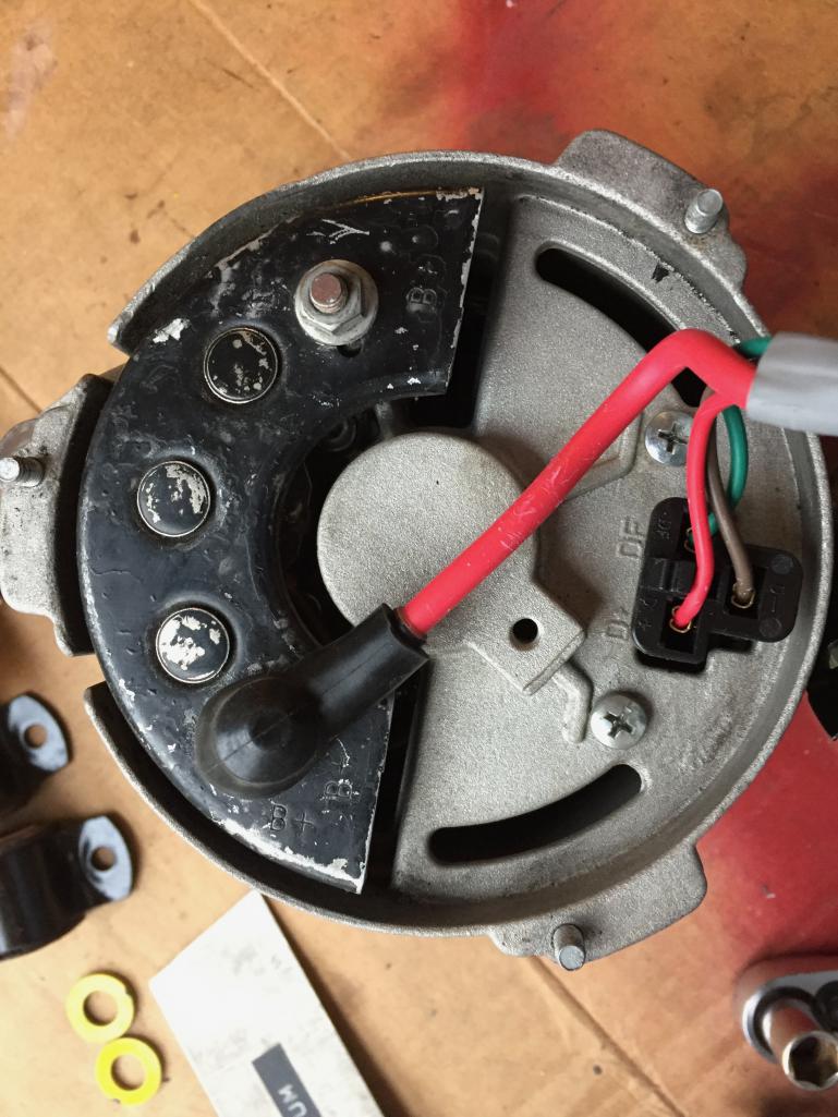 |
|
|
|
| narino |
Mar 28 2019, 09:47 AM
Post
#6
|
|
Member Group: Members Posts: 231 Joined: 14-August 07 From: Los Angeles, CA Member No.: 8,001 Region Association: None |
Barefoot - Ahhhh... This explains a lot. I thought it went to only one terminal.
Do you happen to have a photo of how the wire is routed to the starter? Lots of different sized holes in the engine tin, not sure which is the correct one. Thank you! |
|
|
|
| malcolm2 |
Mar 28 2019, 10:26 AM
Post
#7
|
|
Advanced Member Group: Members Posts: 2,745 Joined: 31-May 11 From: Nashville Member No.: 13,139 Region Association: South East States |
https://colorwiringdiagrams.com/t/porsche
I always spread the word about Prospero's Garage. Awesome wiring diagrams for many different cars.... year and model specific. Looks like they have had a slight price increase. Now $25. |
|
|
|
| ValcoOscar |
Mar 28 2019, 10:34 AM
Post
#8
|
|
Garage Life Group: Members Posts: 2,384 Joined: 19-November 13 From: SoCal Member No.: 16,669 Region Association: Southern California |
I'm in So Cal (90621). If you want drive down Sun AM we can possibly tackle your gremlins together.
I have lifts so we can easily get it up in the air. PM me Oscar |
 |
|
| narino |
Mar 28 2019, 11:48 AM
Post
#9
|
|
Member Group: Members Posts: 231 Joined: 14-August 07 From: Los Angeles, CA Member No.: 8,001 Region Association: None |
malcolm2 - Funny, I just ordered these a few days ago. Looking forward to getting them.
Oscar - Thanks man, I appreciate the invite. The car is in various states of disassembly. When I get her put together enough to be road worthy I'd be down for a road trip to meet another teener. (IMG:style_emoticons/default/beerchug.gif) |
|
|
|
| 76-914 |
Mar 28 2019, 06:08 PM
Post
#10
|
|
Repeat Offender & Resident Subaru Antagonist Group: Members Posts: 13,502 Joined: 23-January 09 From: Temecula, CA Member No.: 9,964 Region Association: Southern California |
That Romex is priceless. (IMG:style_emoticons/default/beerchug.gif)
|
|
|
|
| bbrock |
Mar 28 2019, 07:31 PM
Post
#11
|
|
914 Guru Group: Members Posts: 5,269 Joined: 17-February 17 From: Montana Member No.: 20,845 Region Association: Rocky Mountains |
The hole where the PO's wire runs through the dash is "custom." There should be no hole there. My hunch is the PO had (or thought they had), a problem with the two large (12gauge?) wires that run from the pos battery terminal through the main harness that are the main power feeds to the starter switch and fuse box, and bypassed them through the long. I'd check resistance end to end through those wires end to end and go from there.
I agree that you should chuck that alternator harness and get new. I can't remember for sure, but I believe the 3-wire portion is supposed to feed through the hole just aft of where it is coming through in your pic but covered by foil tape. The hole it is coming through now is for the heater J-tube. If you new alt harness doesn't come with grommets, you can get them from 914Rubber. Good luck! (IMG:style_emoticons/default/beerchug.gif) |
|
|
|
| narino |
Mar 28 2019, 09:10 PM
Post
#12
|
|
Member Group: Members Posts: 231 Joined: 14-August 07 From: Los Angeles, CA Member No.: 8,001 Region Association: None |
bbrock - Thank you! That hole by the dash was going to bug me to no end. Glad I now know it was added by PO. Also per your reply I've rerouted the alternator wiring out of the J-tube hole.
Power wire in the harness: Good thought on possible resistance issue. I think that is what Chi-Town was insinuating, but I didn't pick up on it till now. I'll test for that tomorrow. Starter/Alt wire: Looking at the Flow Diagram I noticed the wire from battery to starter is labeled as 2.5mm. Yet the wire from starter to alternator is 6.0mm. Why wouldn't the wire back to the battery be sized 6.0mm? So glad to finally be finally figuring out these issues. Thanks everyone! (IMG:style_emoticons/default/beer.gif) |
|
|
|
| narino |
Apr 3 2019, 12:56 PM
Post
#13
|
|
Member Group: Members Posts: 231 Joined: 14-August 07 From: Los Angeles, CA Member No.: 8,001 Region Association: None |
Update and more questions.
*edit* Also, thank you to @JeffBowlsby . An email to him straightened out my confusion on why the starter to alternator wire was labeled as a smaller gauge. I need to get my eyes checked, it read 25mm not 2.5mm. *facepalm* |
|
|
|
| Dave_Darling |
Apr 3 2019, 02:14 PM
Post
#14
|
|
914 Idiot Group: Members Posts: 14,986 Joined: 9-January 03 From: Silicon Valley / Kailua-Kona Member No.: 121 Region Association: Northern California |
QUOTE(narino @ Apr 3 2019, 11:56 AM)  [/list]A while back a few wires to my headlight switch burnt out, which is why i'm tracing these wires now. Now that I have most of the wires repaired. How do I test the headlight switch? Here's a dissection of an early switch: http://members.rennlist.com/pbanders/headl...h_internals.htm Later ones are pretty similar. I don't remember the differences off the top of my head, though. --DD |
|
|
|
| narino |
Apr 3 2019, 03:18 PM
Post
#15
|
|
Member Group: Members Posts: 231 Joined: 14-August 07 From: Los Angeles, CA Member No.: 8,001 Region Association: None |
Thank you @Dave_Darling . I had seen that article on pelican, but it doesn't explain how to test the switch with a multimeter. I'm not sure across which pins to test, and if I'm supposed to check for a certain resistance. Sorry, I'm a novice to the electrical stuff.
|
|
|
|
| bbrock |
Apr 3 2019, 03:45 PM
Post
#16
|
|
914 Guru Group: Members Posts: 5,269 Joined: 17-February 17 From: Montana Member No.: 20,845 Region Association: Rocky Mountains |
Since it sounds like you'll be trying to use the original wires for your starter again, a couple things to consider to hopefully avoid whatever problem the PO was trying to fix with the bypass. Consider replacing the electrical starter switch so you know you are starting with a good one (buy the expensive Porsche one), and think about adding a starter relay so you aren't sending a billion amps through your main harness every time you start the car. @Mark_Henry has a good write-up on how to do it.http://www.914world.com/bbs2/index.php?sho...p;mode=threaded. My gut tells me one of those two things might have been behind the reason for the fat red wires up the long.
|
|
|
|
| narino |
Apr 3 2019, 06:33 PM
Post
#17
|
|
Member Group: Members Posts: 231 Joined: 14-August 07 From: Los Angeles, CA Member No.: 8,001 Region Association: None |
Thanks @bbrock . I'm going to rebuild the alternator/starter harness and the battery cables. I did them on my other car and still have the tools and some lugs left over.
I'll definitely look into the Porsche ignition switch and starter relay. Thanks! |
|
|
|
| JeffBowlsby |
Apr 3 2019, 09:16 PM
Post
#18
|
|
914 Wiring Harnesses Group: Members Posts: 8,509 Joined: 7-January 03 From: San Ramon CA Member No.: 104 Region Association: None |
You can test the switches with this:
Attached File(s)  DashSwitches.pdf ( 127.27k )
Number of downloads: 63
DashSwitches.pdf ( 127.27k )
Number of downloads: 63 |
|
|
|
| Dave_Darling |
Apr 3 2019, 09:23 PM
Post
#19
|
|
914 Idiot Group: Members Posts: 14,986 Joined: 9-January 03 From: Silicon Valley / Kailua-Kona Member No.: 121 Region Association: Northern California |
The headlight switch is a switch--or rather, several switches in one housing. With one exception, the pins either contact other pins or don't, so the resistances you are looking for are "infinite" (no connection) or "zero" (dead short or close to it).
The one exception is the instrument light section, which has a rheostat--a variable resistor. All the below is from the 74 wiring diagram; other years may have differences. The headlight switch has three positions; in all the way, out one stop, out all the way. I have labeled those positions 0, 1, and 2 below. (Though I could have those backwards.) Pin 15: Should have no connection to any other pins in switch position 0 or 1. Should connect to 56 and 56K (only those) in switch position 2. Pin 30: Connect to 30b in switch position 0. Connect to pin 57 in switch position 1. Connect to 58L, 58R, K in switch positions 1 and 2. Pin 58a: No connectivity to any switch other than 58b. Variable resistance from 58a to 58b depending on knob rotation. --DD |
|
|
|
| narino |
Apr 3 2019, 11:24 PM
Post
#20
|
|
Member Group: Members Posts: 231 Joined: 14-August 07 From: Los Angeles, CA Member No.: 8,001 Region Association: None |
Jeff & Dave thank you so much!
|
|
|
|
|
1 User(s) are reading this topic (1 Guests and 0 Anonymous Users)
0 Members:

|
Lo-Fi Version | Time is now: 17th May 2024 - 03:24 PM |
Invision Power Board
v9.1.4 © 2024 IPS, Inc.