|
|
|
Porsche, and the Porsche crest are registered trademarks of Dr. Ing. h.c. F. Porsche AG.
This site is not affiliated with Porsche in any way. Its only purpose is to provide an online forum for car enthusiasts. All other trademarks are property of their respective owners. |
|
|

  |

| Chi-town |
 Apr 24 2019, 09:25 AM Apr 24 2019, 09:25 AM
Post
#41
|
|
Senior Member  Group: Members Posts: 851 Joined: 31-August 18 From: Disneyland Member No.: 22,446 Region Association: Southern California |
Just a thought but if you're using a LED chip with an optic and then putting behind a standard thick fluted lens the output is going to be severely reduced. I would guess roughly 30%.
Have you put the standard lens on top of your prototype to see what happens? |
   |

 
|
| Spoke |
Apr 24 2019, 11:11 AM
Post
#42
|
|
Jerry Group: Members Posts: 7,414 Joined: 29-October 04 From: Allentown, PA Member No.: 3,031 Region Association: None |
QUOTE(Chi-town @ Apr 24 2019, 11:25 AM)  Just a thought but if you're using a LED chip with an optic and then putting behind a standard thick fluted lens the output is going to be severely reduced. I would guess roughly 30%. Have you put the standard lens on top of your prototype to see what happens? Not sure how the glass lens will attenuate the light from the LEDs. Once I get the first PCBs populated I'll be able to do some testing on it. The vertical diffusers of the glass lens will tend to broaden the width of the beam. The LED lenses also broaden the beam so maybe I'll have to use more of a spot type of LED lens instead of the 10192 lens and let the glass do the horizontal spreading. |
|
|
|
| Spoke |
Apr 26 2019, 08:01 AM
Post
#43
|
|
Jerry Group: Members Posts: 7,414 Joined: 29-October 04 From: Allentown, PA Member No.: 3,031 Region Association: None |
Have the PCBs in hand. Will assemble the first boards on Monday.
Attached thumbnail(s) 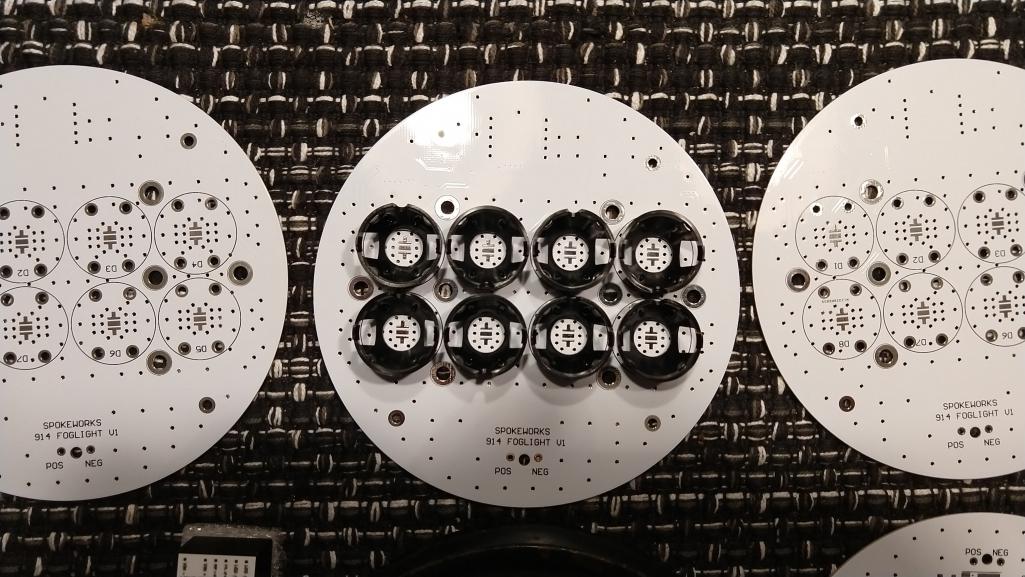
|
|
|
|
| Spoke |
Apr 26 2019, 08:03 AM
Post
#44
|
|
Jerry Group: Members Posts: 7,414 Joined: 29-October 04 From: Allentown, PA Member No.: 3,031 Region Association: None |
Here's the PCB under the glass. It will be interesting to see how the fluted glass will diffuse the beams. The LED lens already provides some lateral diffusion.
The Boostpucks by LEDynamics also arrived. I'll probably power the first prototype with these as it will shorten the time to first light-up. Attached thumbnail(s) 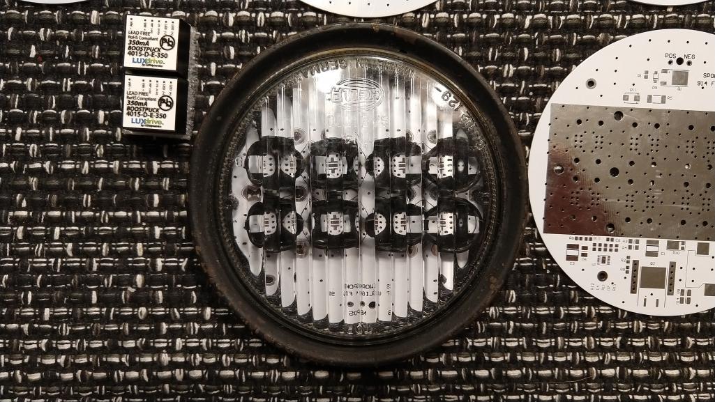
|
|
|
|
| DRPHIL914 |
Apr 26 2019, 08:06 AM
Post
#45
|
|
Dr. Phil Group: Members Posts: 5,956 Joined: 9-December 09 From: Kennesaw, GA Member No.: 11,106 Region Association: South East States |
|
|
|
|
| Spoke |
Apr 29 2019, 01:55 PM
Post
#46
|
|
Jerry Group: Members Posts: 7,414 Joined: 29-October 04 From: Allentown, PA Member No.: 3,031 Region Association: None |
Things like this happen when you set the temperature profile wrong on the infrared oven.
@mepstein I have your foglight board. Not sure why it doesn't light up but I'm working on that. (IMG:style_emoticons/default/beerchug.gif) Attached thumbnail(s) 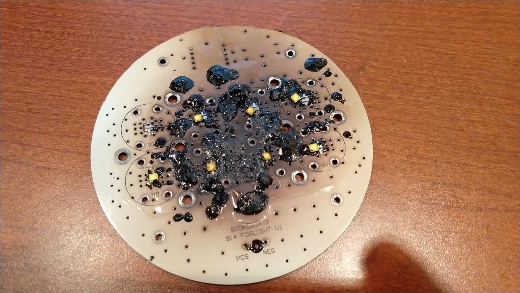
|
|
|
|
| mepstein |
Apr 29 2019, 02:14 PM
Post
#47
|
|
914-6 GT in waiting Group: Members Posts: 20,849 Joined: 19-September 09 From: Landenberg, PA/Wilmington, DE Member No.: 10,825 Region Association: MidAtlantic Region |
QUOTE(Spoke @ Apr 29 2019, 03:55 PM) Things like this happen when you set the temperature profile wrong on the infrared oven. @mepstein I have your foglight board. Not sure why it doesn't light up but I'm working on that. (IMG:style_emoticons/default/beerchug.gif) That looks more like when I try to do electrical work. |
|
|
|
| Spoke |
Apr 29 2019, 03:06 PM
Post
#48
|
|
Jerry Group: Members Posts: 7,414 Joined: 29-October 04 From: Allentown, PA Member No.: 3,031 Region Association: None |
With the correct settings, the oven worked fine.
BTW Mark, this one is mine. Attached thumbnail(s) 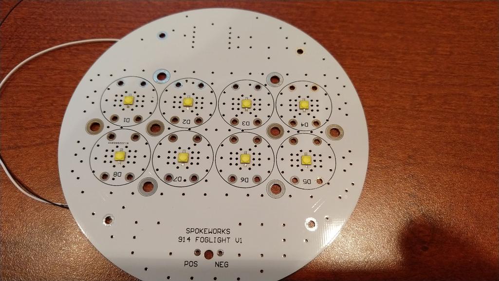
|
|
|
|
| Spoke |
Apr 29 2019, 03:10 PM
Post
#49
|
|
Jerry Group: Members Posts: 7,414 Joined: 29-October 04 From: Allentown, PA Member No.: 3,031 Region Association: None |
All lit up with LED lenses. Won't be able to compare light output until night. Also want to compare with original bulbs.
Attached thumbnail(s) 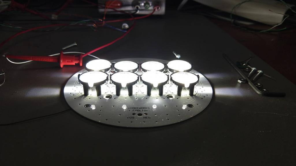
|
|
|
|
| Spoke |
Apr 29 2019, 03:13 PM
Post
#50
|
|
Jerry Group: Members Posts: 7,414 Joined: 29-October 04 From: Allentown, PA Member No.: 3,031 Region Association: None |
Printed a jig to drill the heat sink for tapping. Will be using 6-32 x 3/8 stainless cap screws.
Attached thumbnail(s) 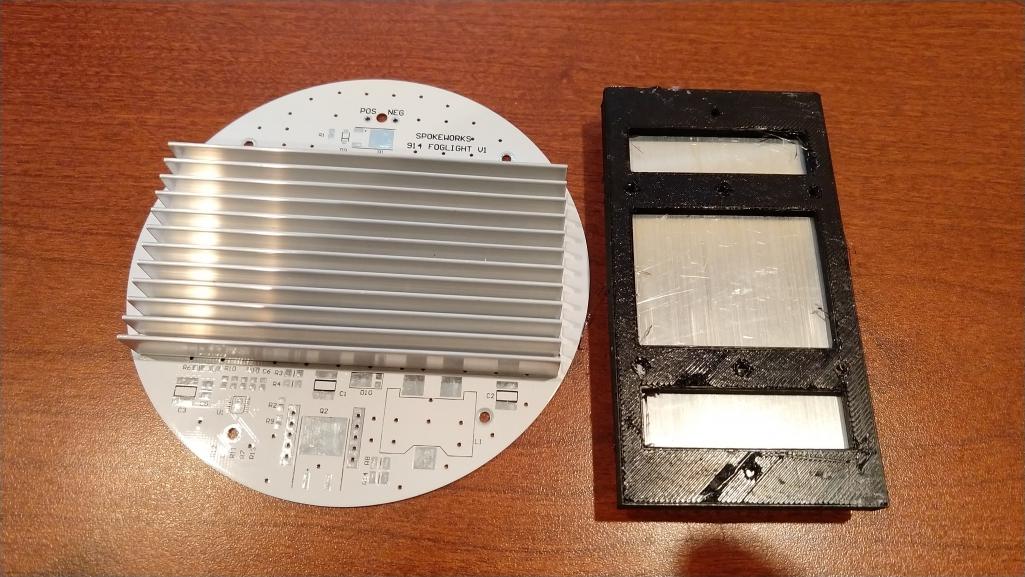
|
|
|
|
| Spoke |
Apr 29 2019, 03:43 PM
Post
#51
|
|
Jerry Group: Members Posts: 7,414 Joined: 29-October 04 From: Allentown, PA Member No.: 3,031 Region Association: None |
Here's the light pattern with 0.5A per LED on the ceiling w/o the glass lens. Basically what the manufacturer said it would be.
Attached thumbnail(s) 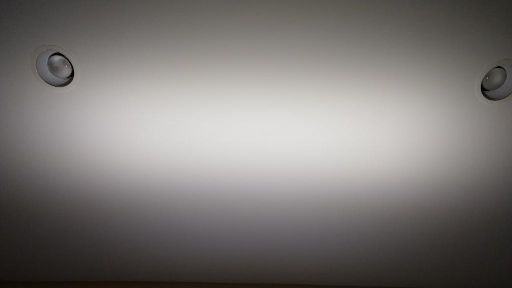
|
|
|
|
| Spoke |
Apr 29 2019, 03:46 PM
Post
#52
|
|
Jerry Group: Members Posts: 7,414 Joined: 29-October 04 From: Allentown, PA Member No.: 3,031 Region Association: None |
The glass lens fits nicely with the printed spacer. I believe the earlier lenses have a deeper cavity.
Attached thumbnail(s) 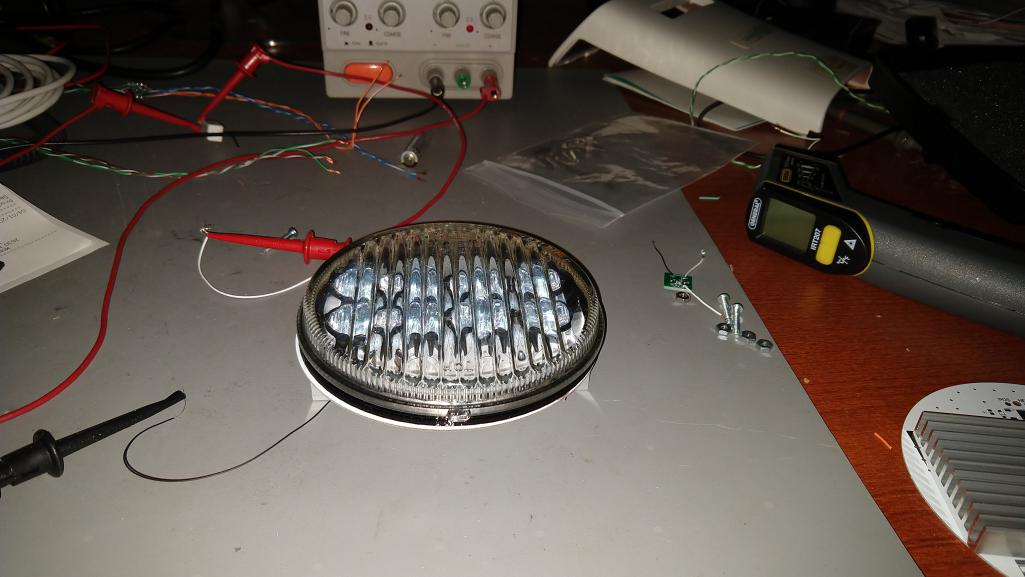
|
|
|
|
| Spoke |
Apr 29 2019, 03:48 PM
Post
#53
|
|
Jerry Group: Members Posts: 7,414 Joined: 29-October 04 From: Allentown, PA Member No.: 3,031 Region Association: None |
Here's the light pattern with 0.5A with the glass lens. The effect of the glass diffusers can be seen.
As Chi-town mentioned, there will be some loss of light because of the glass diffuser. It seems to be about 15%. With 0.5A at 1 meter, I measure: 10000 Lux w/o glass 8500 Lux w/glass At 0.35A at 1 meter: 6000 Lux w/o glass 4500 Lux w/glass Attached thumbnail(s) 
|
|
|
|
| Spoke |
Apr 29 2019, 04:49 PM
Post
#54
|
|
Jerry Group: Members Posts: 7,414 Joined: 29-October 04 From: Allentown, PA Member No.: 3,031 Region Association: None |
Redesigned the spacer rings so the boards can screw into them. This is how they will be assembled.
Attached thumbnail(s) 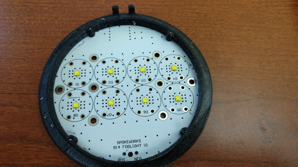
|
|
|
|
| Spoke |
Apr 29 2019, 04:51 PM
Post
#55
|
|
Jerry Group: Members Posts: 7,414 Joined: 29-October 04 From: Allentown, PA Member No.: 3,031 Region Association: None |
These are the wrong screws. These are #4 x 5/16 whereas the correct screws are #2 x 1/4. They'll do for now.
Attached thumbnail(s) 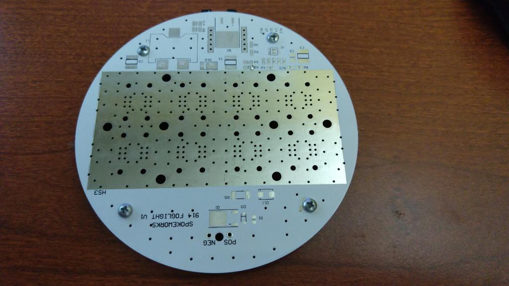
|
|
|
|
| Spoke |
Apr 30 2019, 04:10 AM
Post
#56
|
|
Jerry Group: Members Posts: 7,414 Joined: 29-October 04 From: Allentown, PA Member No.: 3,031 Region Association: None |
The first fully built up PCB. Somehow I managed to not order the correct caps for input and output filtering so had to use smaller lower voltage caps. Original caps should be 100V whereas these are 50V.
 |
|
|
|
| Spoke |
Apr 30 2019, 04:15 AM
Post
#57
|
|
Jerry Group: Members Posts: 7,414 Joined: 29-October 04 From: Allentown, PA Member No.: 3,031 Region Association: None |
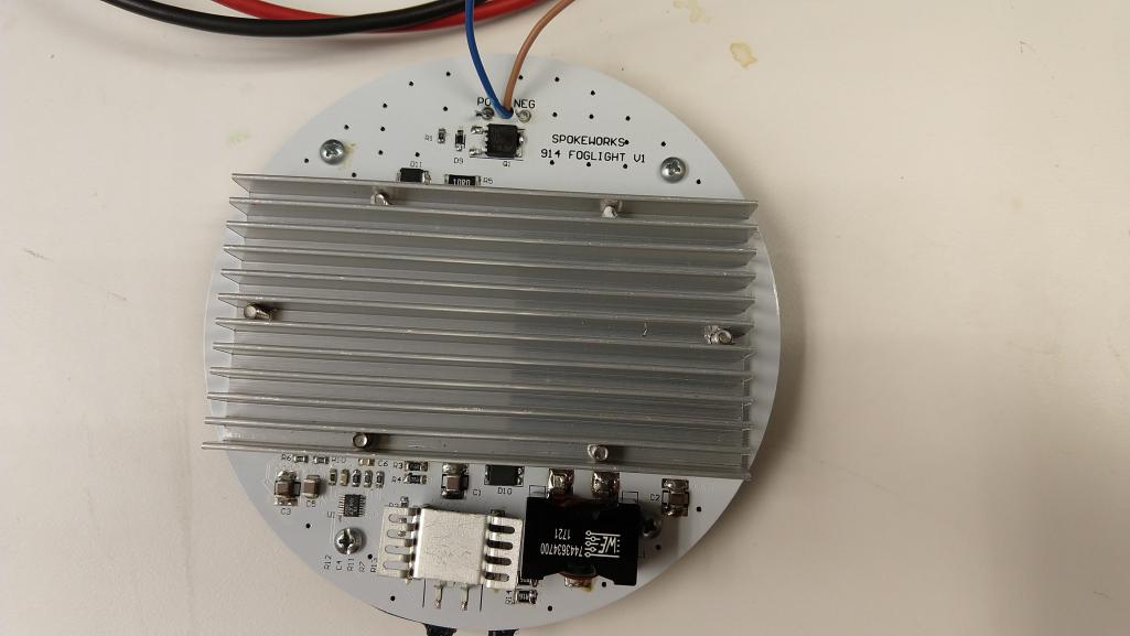
Started doing some burn in on the first unit. Will run this for a couple of days to make sure it works. The LEDs are running 0.5A and the total unit power dissipation is just under 14W or just about 1A at 14V input.
Comparing the light output with the headlights on my '14 328, these are less than 1/2 as bright. The headlights on the 328 measured 19000Lux at 1 meter whereas this unit measured 8700Lux with the glass lens. From early measurements, it looks like there's about a 40C rise in temperatures over ambient. That's about what I expect. It will be interesting to get this in an enclosure and see what happens. Attached thumbnail(s) 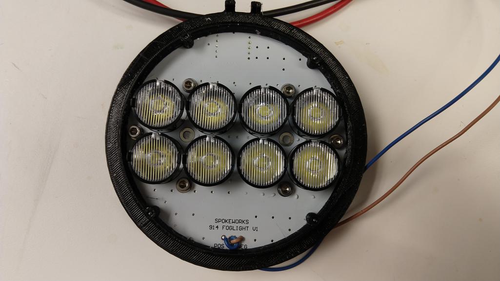
|
|
|
|
| DRPHIL914 |
Apr 30 2019, 05:54 AM
Post
#58
|
|
Dr. Phil Group: Members Posts: 5,956 Joined: 9-December 09 From: Kennesaw, GA Member No.: 11,106 Region Association: South East States |
Looks great!!! Cant wait to get a set!!
That a lot of R&D time invested in these, but looks like it will be worth it |
|
|
|
| jkb944t |
Apr 30 2019, 06:15 AM
Post
#59
|
|
Member Group: Members Posts: 470 Joined: 17-January 05 From: Canton, OH Member No.: 3,459 Region Association: None |
QUOTE(Spoke @ Apr 30 2019, 06:15 AM) Started doing some burn in on the first unit. Will run this for a couple of days to make sure it works. The LEDs are running 0.5A and the total unit power dissipation is just under 14W or just about 1A at 14V input. Comparing the light output with the headlights on my '14 328, these are less than 1/2 as bright. The headlights on the 328 measured 19000Lux at 1 meter whereas this unit measured 8700Lux with the glass lens. From early measurements, it looks like there's about a 40C rise in temperatures over ambient. That's about what I expect. It will be interesting to get this in an enclosure and see what happens. This is so cool, I am really enjoying seeing your progress on this project! Jeff B |
|
|
|
| Spoke |
May 3 2019, 07:59 PM
Post
#60
|
|
Jerry Group: Members Posts: 7,414 Joined: 29-October 04 From: Allentown, PA Member No.: 3,031 Region Association: None |
Burned in the prototype for about 20 hours this week. It still works so that's a good start. With little airflow, the PCB temperature was about 50C above ambient. It will be interesting to see what the temperature rise is when operated in the case.
Put the LEDs in the case. To center the glass lens and LED board, some clips were printed to hold the board while the clips are installed. 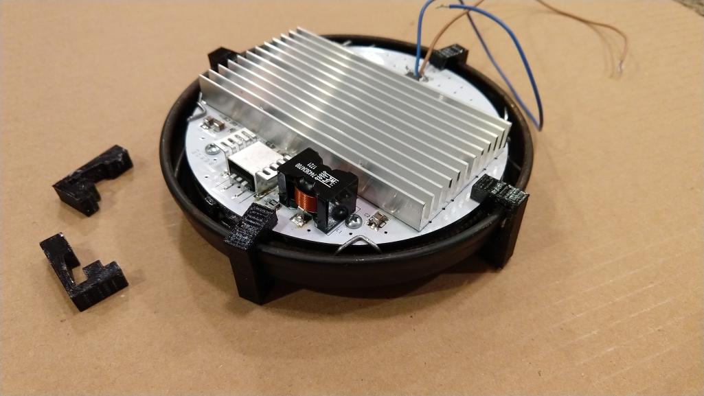 |
|
|
|
|
1 User(s) are reading this topic (1 Guests and 0 Anonymous Users)
0 Members:

|
Lo-Fi Version | Time is now: 2nd August 2026 - 11:55 PM |
Invision Power Board
v9.1.4 © 2026 IPS, Inc.