|
|
|
Porsche, and the Porsche crest are registered trademarks of Dr. Ing. h.c. F. Porsche AG.
This site is not affiliated with Porsche in any way. Its only purpose is to provide an online forum for car enthusiasts. All other trademarks are property of their respective owners. |
|
|


| doug_b_928 |
 May 6 2019, 07:32 PM May 6 2019, 07:32 PM
Post
#1
|
|
Senior Member  Group: Members Posts: 689 Joined: 17-January 13 From: Winnipeg Member No.: 15,382 Region Association: Canada |
I'm building an engine stand that will serve multiple purposes (transport, storage, installation/removal, and testing/break-in). The one part I have very little clue about how to do is the wiring. I've searched the forum and have seen others express an interest in having wiring info for a test stand, but it doesn't seem to be documented anywhere. So, hopefully this thread will help not only me, but also anyone else in the future who is looking to do the same.
I'm going to have the djet 'computer', manifold pressure sensor (MPS), decel valve, fuel pump, and regulator plate/relay board mounted to the stand. The ground that normally connects the battery/engine to the chassis will be grounded to the stand. The wiring for the MPS will be connected to it and the wiring for the fuel injectors, alternator, and 12 pin connector will all be connected to the regulator plate. In other words, it is as if the engine were in the car with the exception of the wiring connections at the 14 pin connector on the regulator plate. On the stand's 'dash board' I think (please correct me if I'm wrong) I need an ignition toggle switch, a momentary starter switch, an oil pressure 'idiot' light (I'm getting a cheap LED light on sale tomorrow), a tachometer (I have a cheap, generic one from FLAPS), and lever with a cable for controlling the throttle. So the question is, what is the correct way to wire these items? I have the figures from Jeff Bowlsby's webpage and the wiring diagrams. What I'm missing is the theory of what I need to do wiring-wise to make the engine run and get the feedback to the tachometer and idiot light. I'm hoping others who appear to have done this can chime in with their thoughts (paging @StratPlayer @VaccaRabite @michelko @mb911 @barefoot ) and wiring gurus (like @JeffBowlsby ). I assume I run wires from the battery to the two power pins on the 14 pin connector, so that the regulator plate has power. After that, although I think it should be pretty simple, I'm not 100% on how to wire the ignition, starter, tach and idiot light to the 14 pin connector. Please advise. |
   |

 
|
  |
Replies(1 - 19)
| Spoke |
May 6 2019, 09:47 PM
Post
#2
|
|
Jerry Group: Members Posts: 6,972 Joined: 29-October 04 From: Allentown, PA Member No.: 3,031 Region Association: None |
Here's a schematic of the relay board to help with the connections.
In addition to the pins below, you'll need a heavy cable bolted from the battery to the starter as well as a heavy cable bolted to the case of the engine. When I tested an engine I would use a hollow transmission case I got from Dr. Evil to mount the starter. I assume you have a master ON/OFF switch to these electrics from the battery. This would be your ignition switch. Should be a heavy switch much like an AC light switch (15A). Assume the name for this switched 12V signal is VCC. You may want to fuse VCC to the electrics just in case of a short. A 25A or 30A fuse would do. The connections of the 14-pin relay board connector to the cabin: Pin 1: Starter: Connect a push-button switch between this pin and VCC. Should be able to handle 10A Pin 2: Gen Light: Connect an incandescent light from this pin to VCC. Pin 5: Oil Pressure: Connect a lamp from this pin to VCC. Pin 7: Tachometer: Connect the tachometer input to this pin. Pin 8: Ignition: Connect to VCC. Pin 10: Ground: Connect to negative terminal of the battery. Pin 12, 14: Battery: In the car these pins are powered 100% of the time. Here it could be connected to VCC. Pin 13: Fuel pump: Connect the positive terminal of the fuel pump to this pin. The negative terminal of the fuel pump should be connected to ground. 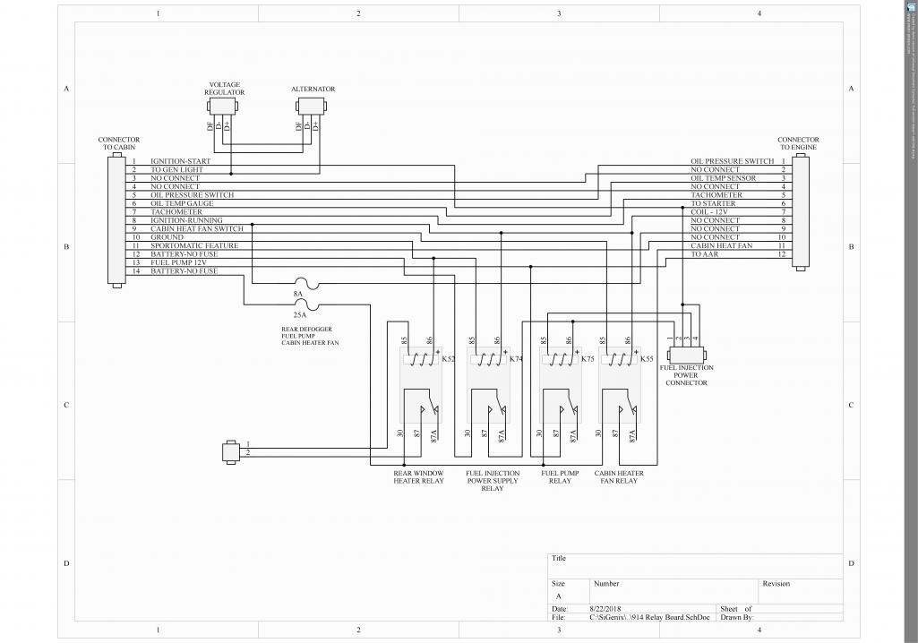 |
|
|
|
| Literati914 |
May 6 2019, 09:52 PM
Post
#3
|
|
Senior Member Group: Members Posts: 1,428 Joined: 16-November 06 From: Dallas, TX Member No.: 7,222 Region Association: Southwest Region |
this is soo timely for me.. been thinking on this too. I have an uninstalled, but newly rebuilt 1.7L w/D-jet that I inherited w/my '72.
|
|
|
|
| doug_b_928 |
May 7 2019, 05:39 AM
Post
#4
|
|
Senior Member Group: Members Posts: 689 Joined: 17-January 13 From: Winnipeg Member No.: 15,382 Region Association: Canada |
@Spoke --This is terrific, thank you so much!!! I'll study what you've said and report back with questions for clarification.
@Literati914 --As suspected, this thread is badly needed. Glad it will help more than just myself. |
|
|
|
| doug_b_928 |
May 7 2019, 06:43 AM
Post
#5
|
|
Senior Member Group: Members Posts: 689 Joined: 17-January 13 From: Winnipeg Member No.: 15,382 Region Association: Canada |
Thanks again for the SUPER CLEAR and straightforward instructions. Despite that, being me, I still have some questions for clarification:
1. Out of curiosity, what does the acronym VCC stand for? 2. For the heavy cable that goes directly from the battery + to starter, from battery + to VCC switch, and from battery - to engine and engine stand, should that be 4 gauge cable? 3. Re fusing, so should there be an in-line fuse for each electric powered by VCC? 4. What gauge of wiring is recommended for going from VCC to the electrics? 5. For the Gen light you specify an incandescent light. I'm guessing that's purposeful. My FLAPS has LED ones that I thought I'd use (I don't see incandescent versions on their website). Will these work (here's a link: https://www.princessauto.com/en/detail/gree...ght/A-p8172736e )? 6. For grounding the fuel pump, on my car it was grounded to the chassis. Is it better to connect it to the battery - or the engine stand, or no difference either way? |
|
|
|
| Spoke |
May 7 2019, 07:37 AM
Post
#6
|
|
Jerry Group: Members Posts: 6,972 Joined: 29-October 04 From: Allentown, PA Member No.: 3,031 Region Association: None |
QUOTE(doug_b_928 @ May 7 2019, 08:43 AM)  Thanks again for the SUPER CLEAR and straightforward instructions. Despite that, being me, I still have some questions for clarification: 1. Out of curiosity, what does the acronym VCC stand for? I believe it comes from transistor circuits where the positive voltage supply is named because an NPN transistor's collector pin goes to the positive voltage. Likewise, a negative voltage is sometimes called VEE since the NPN transistor's emitter pin goes towards the negative voltage source. In general, it could be called anything. My first thought was to call it VSPOKE. (IMG:style_emoticons/default/piratenanner.gif) QUOTE 2. For the heavy cable that goes directly from the battery + to starter, from battery + to VCC switch, and from battery - to engine and engine stand, should that be 4 gauge cable? Yes, 4 gauge is fine. You can pick this up at your FLAPS. Get cables with the battery clamp attached. The positive one should have an extra small wire coming off the clamp to run the electrics. It is very important that the battery cables be bolted onto the battery and starter and engine case. If spring clamps are used like jumper cables, it is possible for the clamps to come loose or make a bad connection and possibly damage the alternator when running. QUOTE 3. Re fusing, so should there be an in-line fuse for each electric powered by VCC? You could do that although one fuse would be there just in case something gets shorted. The battery power in the 914 to pins 12 and 14 have no fuses between them and the battery. The fuse would be the wires themselves or the relay board. QUOTE 4. What gauge of wiring is recommended for going from VCC to the electrics? The same size as on the car. Looks like 10-14 gauge or so. QUOTE 5. For the Gen light you specify an incandescent light. I'm guessing that's purposeful. My FLAPS has LED ones that I thought I'd use (I don't see incandescent versions on their website). Will these work (here's a link: https://www.princessauto.com/en/detail/gree...ght/A-p8172736e )? This one must be incandescent and should be the same wattage as specified for the 914 GEN light. The current through this light could go one way or the other and needs to have a pure resistive characteristic. LEDs do not do that. They sometimes need several volts across them to turn on and light up. Also if the wattage isn't high enough, the alternator may not bootstrap itself into operation. QUOTE 6. For grounding the fuel pump, on my car it was grounded to the chassis. Is it better to connect it to the battery - or the engine stand, or no difference either way? The battery negative terminal or the engine case will be your chassis ground. |
|
|
|
| VaccaRabite |
May 7 2019, 07:44 AM
Post
#7
|
|
En Garde! Group: Admin Posts: 13,420 Joined: 15-December 03 From: Dallastown, PA Member No.: 1,435 Region Association: MidAtlantic Region |
Hey Doug
The Gen light needs to be incandescent as the alternator uses it to help turn on. Sounds crazy, but that's how it works. For the fuel pump - everything eventually grounds to the negative terminal on the battery. How you have it grounded does not really matter so long as your grounds are clean. If you are going through the effort of building a run in bench, add a fuse panel. They are inexpensive and you can get decent ones easily. when I built my run in stand / install cart I was just using carbs and the wiring was much simpler. I only had a big button for the starter (that was independent of the master power so I could build oil pressure), a smaller switch for ignition power and fuel pump, and a wire for a tach. I did not bother with the alternator at the time. While having a run-in bench is handy for finding the oil leaks you missed when building the engine, with the full Djet or EFI I'm not sure its worth the time do build vs putting the engine in the car and hooking everything up there. Zach |
|
|
|
| Mark Henry |
May 7 2019, 07:54 AM
Post
#8
|
|
that's what I do! Group: Members Posts: 20,065 Joined: 27-December 02 From: Port Hope, Ontario Member No.: 26 Region Association: Canada |
Watching this, I have a test stand, but what I need to build is a easily removable electric box because I often store the stand outside.
|
|
|
|
| doug_b_928 |
May 7 2019, 07:58 AM
Post
#9
|
|
Senior Member Group: Members Posts: 689 Joined: 17-January 13 From: Winnipeg Member No.: 15,382 Region Association: Canada |
[quote name='Spoke' date='May 7 2019, 08:37 AM' post='2711756']
I believe it comes from transistor circuits where the positive voltage supply is named because an NPN transistor's collector pin goes to the positive voltage. Likewise, a negative voltage is sometimes called VEE since the NPN transistor's emitter pin goes towards the negative voltage source. In general, it could be called anything. My first thought was to call it VSPOKE. (IMG:style_emoticons/default/piratenanner.gif) [quote] Thanks for the explanation and it shows my level of knowledge that I didn't understand any of it! (IMG:style_emoticons/default/headbang.gif) [/quote] The positive one should have an extra small wire coming off the clamp to run the electrics. [quote] I'm a bit confused by this. I thought everything for the electrics (except the starter) followed through the VCC... [/quote] The fuse would be the wires themselves or the relay board. [quote] Yikes, don't want the relay board to be the fuse! [/quote] This one must be incandescent and should be the same wattage as specified for the 914 GEN light. The current through this light could go one way or the other and needs to have a pure resistive characteristic. LEDs do not do that. They sometimes need several volts across them to turn on and light up. Also if the wattage isn't high enough, the alternator may not bootstrap itself into operation. [quote] Wow! Incandescent it is. |
|
|
|
| doug_b_928 |
May 7 2019, 08:13 AM
Post
#10
|
|
Senior Member Group: Members Posts: 689 Joined: 17-January 13 From: Winnipeg Member No.: 15,382 Region Association: Canada |
Thanks for chiming in Zach.
I was thinking a fuse panel too. I have a spare 914 panel but it's 120 miles away. I also think I have a spare 14 pin connector with the terminals there as well so I guess I'll wait to hook it up until I can get there and bring back those items (will make for a much nicer install). I like the idea of having the starter button independent of the ignition to allow building oil pressure. I guess with a fused panel I can just pull the fuel pump fuse and turn the engine over to build oil pressure and avoid dumping fuel into the cylinders. Agreed re time vs just putting it in the car, but in my case the car is completely disassembled to a shell and won't be reassembled (including re-installation of the wiring harness and electrics) for a few years. This will allow me to do a rebuild and break-in etc. during times when I can't work on the car for other reasons. Plus, it's going to be fun! |
|
|
|
| Spoke |
May 7 2019, 09:42 AM
Post
#11
|
|
Jerry Group: Members Posts: 6,972 Joined: 29-October 04 From: Allentown, PA Member No.: 3,031 Region Association: None |
QUOTE(doug_b_928 @ May 7 2019, 09:58 AM) QUOTE(Spoke @ May 7 2019, 08:37 AM) The positive one should have an extra small wire coming off the clamp to run the electrics. I'm a bit confused by this. I thought everything for the electrics (except the starter) followed through the VCC... You are correct. The main power switch would be connected to the small wire coming from the battery perhaps through a fuse or fuse-able link. The switched side of the switch is VCC. |
|
|
|
| doug_b_928 |
May 7 2019, 09:51 AM
Post
#12
|
|
Senior Member Group: Members Posts: 689 Joined: 17-January 13 From: Winnipeg Member No.: 15,382 Region Association: Canada |
Oh, okay, so the big positive cable is only to the starter and a smaller (maybe 12g) wire also goes from the battery to the master switch.
|
|
|
|
| doug_b_928 |
May 11 2019, 08:59 AM
Post
#13
|
|
Senior Member Group: Members Posts: 689 Joined: 17-January 13 From: Winnipeg Member No.: 15,382 Region Association: Canada |
I'm making good progress on the stand, but have a question re the schematic: Just to confirm my understanding of the schematic and the wiring diagram, the two supply voltage lines that come from VCC and go to pins 12 and 14 only supply power via the relay board to the Fuel Pump and the Fuel Injection Power Connector, correct? In other words, this is why VCC still needs to be supplied directly to the ignition, oil pressure light, generator light, tachometer, and starter, but not to the fuel pump).
P.S. In thinking about my previous comment re the fuel pump fuse, I realized that it's obvious I can just put a toggle switch between pin 13 and the fuel pump + to control power to the fuel pump separately. |
|
|
|
| Spoke |
May 11 2019, 09:09 PM
Post
#14
|
|
Jerry Group: Members Posts: 6,972 Joined: 29-October 04 From: Allentown, PA Member No.: 3,031 Region Association: None |
Maybe this schematic can clear up some questions.
In this schematic, the battery is shown on the left side. The negative terminal is connected to the engine case or trans case. The engine/trans case becomes the ground for the entire system. The heavy wire from the positive battery terminal goes to the starter while the smaller wire goes to fuse F3 then to the ignition switch S2. Ignition switch S1 provides the VCC power to the engine. Note that Starter switch S1 bypasses the ignition switch. This allows the engine to be rotated via the starter without the electrics being alive. So for a new build one can rotate the engine to build up oil pressure before firing the engine. The OIL pressure light also is powered directly from the battery so when cranking the engine with electrics off the OIL light will still work. This schematic is just a suggestion. Any changes are welcome. 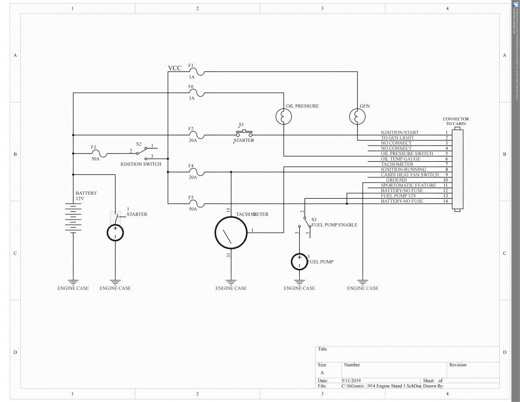 |
|
|
|
| Spoke |
May 11 2019, 09:17 PM
Post
#15
|
|
Jerry Group: Members Posts: 6,972 Joined: 29-October 04 From: Allentown, PA Member No.: 3,031 Region Association: None |
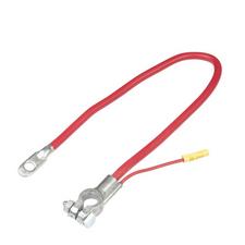
This is the type of positive battery cable to use. Heavy cable to the starter and thinner cable to the electrics.
 |
|
|
|
| doug_b_928 |
May 12 2019, 07:05 AM
Post
#16
|
|
Senior Member Group: Members Posts: 689 Joined: 17-January 13 From: Winnipeg Member No.: 15,382 Region Association: Canada |
That's very helpful, and professional, thanks Spoke!! It confirms that, among the peripherals I'm hooking up, only the fuel pump is getting power directly from the relay board.
Attached is my relatively pathetic looking hand drawing of what I have planned. I have a spare 914 fuse panel so figured I'd incorporate it. In this plan there is a toggle interrupting power to the fuel pump to allow cranking the engine over to build oil pressure while still having the oil pressure light powered. I know my drawing probably looks like an unnecessarily complicated way to do it, but is it ok/any problems with it?  Engine_Run_Stand_Wiring_for_1973_DJet.pdf ( 566.13k )
Number of downloads: 89
Engine_Run_Stand_Wiring_for_1973_DJet.pdf ( 566.13k )
Number of downloads: 89 |
|
|
|
| doug_b_928 |
May 15 2019, 05:01 PM
Post
#17
|
|
Senior Member Group: Members Posts: 689 Joined: 17-January 13 From: Winnipeg Member No.: 15,382 Region Association: Canada |
I purchased this switch for the VCC switch and starter:
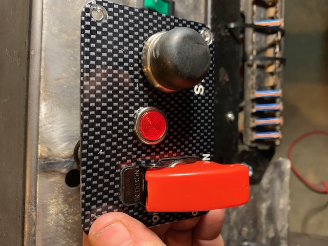 It has a light which should come on when the ignition has power. It didn't come with instructions (I guess it's so simple it shouldn't need them, but I'm a dummy). So, I watched a youtube video on installing a similar switch and the guy said that the light needs to go to ground. The light has two wires so I figured one would come from the 'out' side of the ignition switch/VCC (so it will light when the ignition is on) and the other should then go to ground. It was a short wire with a ring terminal so I cut it and added a longer wire to the engine stand ground. But, when I test for continuity, the test for the 'supply voltage' at the connector I made for the Regulator board not only shows continuity where it should, but also there is continuity to anywhere on the engine stand (i.e., to ground). I disconnected the wire on the light from the ignition switch and that solved the problem. Here's a pic of the wiring for the switch and I've disconnected the wire from the light to the ignition switch. 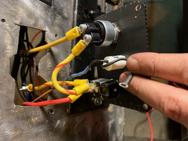 So, long story short, what is the correct way to connect the light? |
|
|
|
| doug_b_928 |
May 15 2019, 08:54 PM
Post
#18
|
|
Senior Member Group: Members Posts: 689 Joined: 17-January 13 From: Winnipeg Member No.: 15,382 Region Association: Canada |
In thinking about it, I’m guessing that I had the wire from the ignition switch to the light correct, but that the second wire from the light was intended to go to the starter. I.e., VCC is carried through the light to the starter button. Sound correct?
|
|
|
|
| doug_b_928 |
May 16 2019, 03:15 PM
Post
#19
|
|
Senior Member Group: Members Posts: 689 Joined: 17-January 13 From: Winnipeg Member No.: 15,382 Region Association: Canada |
Overthinking, again... I’ve realized that I had it correct in the first place.
|
|
|
|
| doug_b_928 |
May 16 2019, 05:02 PM
Post
#20
|
|
Senior Member Group: Members Posts: 689 Joined: 17-January 13 From: Winnipeg Member No.: 15,382 Region Association: Canada |
Many thanks to Spoke for all of his helpful information and advice above. Attached is my revised drawing of what I think will be the final wiring for the stand, in case anyone ever wants to replicate it.
Engine_Run_Stand_Wiring_for_1973_DJet.pdf ( 638.54k )
Number of downloads: 127 |
|
|
|
|
1 User(s) are reading this topic (1 Guests and 0 Anonymous Users)
0 Members:

|
Lo-Fi Version | Time is now: 20th April 2024 - 02:41 AM |
Invision Power Board
v9.1.4 © 2024 IPS, Inc.