|
|
|
Porsche, and the Porsche crest are registered trademarks of Dr. Ing. h.c. F. Porsche AG.
This site is not affiliated with Porsche in any way. Its only purpose is to provide an online forum for car enthusiasts. All other trademarks are property of their respective owners. |
|
|

  |

| buck toenges |
 May 15 2019, 05:24 PM May 15 2019, 05:24 PM
Post
#1
|
|
Senior Member  Group: Members Posts: 554 Joined: 25-November 03 From: Fort wayne In Member No.: 1,388 Region Association: None |
I have decided to place my thermostat in the front trunk. I think it is easier for me to do that. I am routing the oil lines back to the engine compartment. Here are a few pics of my current set up on my 3.2. I could use some help plumbing the new oil lines back to the engine and oil tank. Can you tell me how to connect the new oil lines to the current oil lines please.
Here is the line from the bottom of engine to the oil tank. 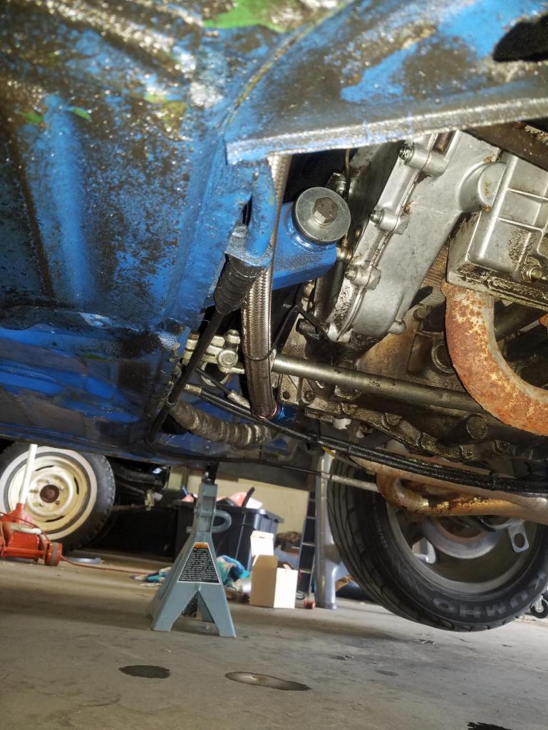 Here is the oil line from the tank. I am not sure where it goes. 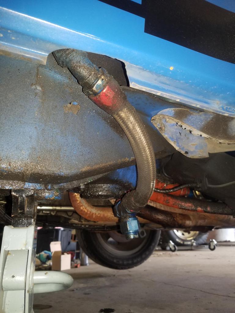 Here is another picture of this line that has the oil removal plug. 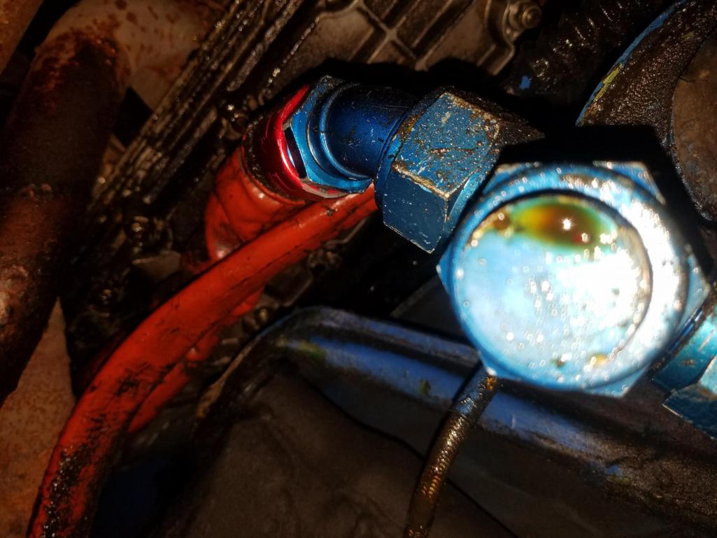 I didn't picture the other oil line on top of the oil tank that I thinks goes to the cooler on the engine. So I am looking if I can use any of these lines in conjunction with the two oil lines coming back to the engine compartment on the drivers side. Thanks, Buck |
   |

 
|
| Mike D. |
May 15 2019, 05:30 PM
Post
#2
|
|
OK, It runs now, and pretty good too! Group: Members Posts: 1,457 Joined: 3-January 03 From: Santa Clarita, Ca Member No.: 85 Region Association: None |
What line are you using to go to the front? Less fittings the better.
Engine to Thermostat, thermostat to tank. The line from tank to pump stays. Oh, and be prepared to get a lot you didn't ask about... |
|
|
|
| mepstein |
May 15 2019, 05:56 PM
Post
#3
|
|
914-6 GT in waiting Group: Members Posts: 20,669 Joined: 19-September 09 From: Landenberg, PA/Wilmington, DE Member No.: 10,825 Region Association: MidAtlantic Region |
Its a bit hard to see the big picture from your pics. It’s good to sketch the layout on a piece of paper noting line size (diameter), fitting, direction, etc.
|
|
|
|
| Krieger |
May 15 2019, 06:32 PM
Post
#4
|
|
Advanced Member Group: Members Posts: 4,855 Joined: 24-May 04 From: Santa Rosa CA Member No.: 2,104 Region Association: None |
Your oil removal plug is really close to the ground.
|
 |
|
| mepstein |
May 15 2019, 06:41 PM
Post
#5
|
|
914-6 GT in waiting Group: Members Posts: 20,669 Joined: 19-September 09 From: Landenberg, PA/Wilmington, DE Member No.: 10,825 Region Association: MidAtlantic Region |
QUOTE(Krieger @ May 15 2019, 08:32 PM)  Your oil removal plug is really close to the ground. I have one like that but the plug is parallel to the ground. The loop is still the lowest spot so it drains without the plug pointing down. It’s easy to adjust the angle just by loosening the fittings. |
|
|
|
| mb911 |
May 15 2019, 07:03 PM
Post
#6
|
|
914 Guru Group: Members Posts: 7,759 Joined: 2-January 09 From: Burlington wi Member No.: 9,892 Region Association: Upper MidWest |
Are you asking what line connects to the oil cooler???
If so basically you split the scavange line in half. One have connects to the front oil cooler and one half connects to the return portion that gets plumbed backed to scavange return into the tank. |
|
|
|
| sixnotfour |
May 22 2019, 02:55 PM
Post
#7
|
|
914 Wizard Group: Members Posts: 11,219 Joined: 12-September 04 Member No.: 2,744 Region Association: NineFourteenerVille |
the one with the drain T is the direct supply to the engine...stays as is....
braided line running along fire wall is the return line to oil tank.. after it goes thru motor....hot that line now needs too be routed to one of the hard lines... The other hard line need a hose to go back to the tank... Question...what is in the heat wrap by the oil line,,by the fire wall ? fuel lines ? |
|
|
|
| mb911 |
May 22 2019, 03:20 PM
Post
#8
|
|
914 Guru Group: Members Posts: 7,759 Joined: 2-January 09 From: Burlington wi Member No.: 9,892 Region Association: Upper MidWest |
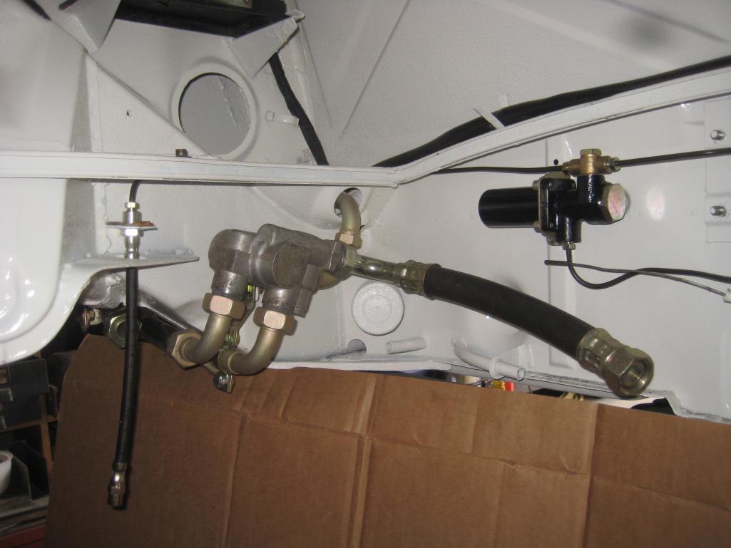
This is a decent picture but pbase has more pictures of the real setup.
 |
|
|
|
| rgalla9146 |
May 22 2019, 06:16 PM
Post
#9
|
|
Advanced Member Group: Members Posts: 4,958 Joined: 23-November 05 From: Paramus NJ Member No.: 5,176 Region Association: None |
QUOTE(sixnotfour @ May 22 2019, 04:55 PM) the one with the drain T is the direct supply to the engine...stays as is.... braided line running along fire wall is the return line to oil tank.. after it goes thru motor....hot that line now needs too be routed to one of the hard lines... The other hard line need a hose to go back to the tank... Question...what is in the heat wrap by the oil line,,by the fire wall ? fuel lines ? (IMG:style_emoticons/default/agree.gif) The pictured line with the drain cap extends from the bottom of the tank to the fitting on the bottom of the engine mounted oil cooler. Thermostats fit inline to the plumbing that extends from the right side of the engine to the fitting on the engine side of the tank. Ben used a picture of my thermostat plumbing. I used a 911 thermo......not a common choice......there are simpler ways to get a working system. Thanks Ben. Nice to know you noticed. |
|
|
|
| mb911 |
May 22 2019, 07:47 PM
Post
#10
|
|
914 Guru Group: Members Posts: 7,759 Joined: 2-January 09 From: Burlington wi Member No.: 9,892 Region Association: Upper MidWest |
QUOTE(rgalla9146 @ May 22 2019, 04:16 PM) QUOTE(sixnotfour @ May 22 2019, 04:55 PM) the one with the drain T is the direct supply to the engine...stays as is.... braided line running along fire wall is the return line to oil tank.. after it goes thru motor....hot that line now needs too be routed to one of the hard lines... The other hard line need a hose to go back to the tank... Question...what is in the heat wrap by the oil line,,by the fire wall ? fuel lines ? (IMG:style_emoticons/default/agree.gif) The pictured line with the drain cap extends from the bottom of the tank to the fitting on the bottom of the engine mounted oil cooler. Thermostats fit inline to the plumbing that extends from the right side of the engine to the fitting on the engine side of the tank. Ben used a picture of my thermostat plumbing. I used a 911 thermo......not a common choice......there are simpler ways to get a working system. Thanks Ben. Nice to know you noticed. I like it and will do it that way on my car as well. |
|
|
|
| worn |
May 22 2019, 09:56 PM
Post
#11
|
|
Winner of the Utah Twisted Joint Award Group: Members Posts: 3,573 Joined: 3-June 11 From: Madison, WI and North Bend WA Member No.: 13,152 Region Association: Upper MidWest |
QUOTE(mb911 @ May 22 2019, 01:20 PM) This is a decent picture but pbase has more pictures of the real setup. That your car Ben? Looks great. |
|
|
|
| mepstein |
May 23 2019, 05:27 AM
Post
#12
|
|
914-6 GT in waiting Group: Members Posts: 20,669 Joined: 19-September 09 From: Landenberg, PA/Wilmington, DE Member No.: 10,825 Region Association: MidAtlantic Region |
QUOTE(worn @ May 22 2019, 11:56 PM) QUOTE(mb911 @ May 22 2019, 01:20 PM) This is a decent picture but pbase has more pictures of the real setup. That your car Ben? Looks great. rgalla9146/Rory’s white GT. |
|
|
|
| sixnotfour |
May 23 2019, 09:30 AM
Post
#13
|
|
914 Wizard Group: Members Posts: 11,219 Joined: 12-September 04 Member No.: 2,744 Region Association: NineFourteenerVille |
QUOTE I have decided to place my thermostat in the front trunk. I think it is easier for me to do that. Is why I worded my reply the way I did.... Yes Rory's is nice.. (IMG:style_emoticons/default/beerchug.gif) |
|
|
|
| buck toenges |
May 23 2019, 11:25 AM
Post
#14
|
|
Senior Member Group: Members Posts: 554 Joined: 25-November 03 From: Fort wayne In Member No.: 1,388 Region Association: None |
QUOTE(sixnotfour @ May 22 2019, 04:55 PM) the one with the drain T is the direct supply to the engine...stays as is.... braided line running along fire wall is the return line to oil tank.. after it goes thru motor....hot that line now needs too be routed to one of the hard lines... The other hard line need a hose to go back to the tank... Question...what is in the heat wrap by the oil line,,by the fire wall ? fuel lines ? It is actually heat wrap over the e-brake. Can't tell you why this was done. Buck |
|
|
|
|
1 User(s) are reading this topic (1 Guests and 0 Anonymous Users)
0 Members:

|
Lo-Fi Version | Time is now: 5th May 2026 - 12:08 AM |
Invision Power Board
v9.1.4 © 2026 IPS, Inc.