|
|
|
Porsche, and the Porsche crest are registered trademarks of Dr. Ing. h.c. F. Porsche AG.
This site is not affiliated with Porsche in any way. Its only purpose is to provide an online forum for car enthusiasts. All other trademarks are property of their respective owners. |
|
|

  |

| John |
 Dec 8 2020, 10:14 PM Dec 8 2020, 10:14 PM
Post
#61
|
|
member? what's a member?  Group: Members Posts: 3,393 Joined: 30-January 04 From: Evansville, IN (SIRPCA) Member No.: 1,615 Region Association: None |
QUOTE(Root_Werks @ Dec 8 2020, 08:05 AM)  QUOTE(watsonrx13 @ Dec 8 2020, 05:50 AM) Well done John. Do you have any in progress photos of a fender installation? Or can you write up the steps you used? Specifically I'm interested in how you mounted the fender to the car and how you cut the old fender, keeping the new fender in position. I've installed 3 of the AA sets, pretty straight forward. I did one thread on it: http://www.914world.com/bbs2/index.php?sho...=89850&st=0 Looks like John is installing sort of similar. Looks great! Watsonrx13, Dan is mostly right. On this set of flares, I started the first one by carefully marking and cutting the fender then fitting the flare to the cut fender. The last three flares on this project were done how Dan showed in the thread he referenced. His thread is from a while ago, but it turned out far easier than cutting the whole fender at once. The basic method used was to carefully measure and mark the bottoms of the flares to the existing fenders and starting tack welding and cutting about 7-8" at a time then tack welding. I moved from front to back and worked my way up to the tops of the flare as I went. They really do fit nicely. Take your time and put as little heat into the sheet metal as possible. I'm far better at MIG than TIG, so these are MIG welded one spot at a time. I used measurements that seemed to match found on this site as well as on a Patrick Motorsports page to get the openings positioned fore-aft. I also used my existing full scale 3D model as a reference for dimensions. |
   |

 
|
| watsonrx13 |
Dec 9 2020, 06:57 AM
Post
#62
|
|
Advanced Member Group: Members Posts: 2,735 Joined: 18-February 03 From: Plant City, FL Member No.: 312 Region Association: South East States |
Thanks everyone.
|
|
|
|
| mb911 |
Dec 9 2020, 07:38 AM
Post
#63
|
|
914 Guru Group: Members Posts: 7,794 Joined: 2-January 09 From: Burlington wi Member No.: 9,892 Region Association: Upper MidWest |
QUOTE(John @ Dec 8 2020, 08:14 PM) QUOTE(Root_Werks @ Dec 8 2020, 08:05 AM) QUOTE(watsonrx13 @ Dec 8 2020, 05:50 AM) Well done John. Do you have any in progress photos of a fender installation? Or can you write up the steps you used? Specifically I'm interested in how you mounted the fender to the car and how you cut the old fender, keeping the new fender in position. I've installed 3 of the AA sets, pretty straight forward. I did one thread on it: http://www.914world.com/bbs2/index.php?sho...=89850&st=0 Looks like John is installing sort of similar. Looks great! Watsonrx13, Dan is mostly right. On this set of flares, I started the first one by carefully marking and cutting the fender then fitting the flare to the cut fender. The last three flares on this project were done how Dan showed in the thread he referenced. His thread is from a while ago, but it turned out far easier than cutting the whole fender at once. The basic method used was to carefully measure and mark the bottoms of the flares to the existing fenders and starting tack welding and cutting about 7-8" at a time then tack welding. I moved from front to back and worked my way up to the tops of the flare as I went. They really do fit nicely. Take your time and put as little heat into the sheet metal as possible. I'm far better at MIG than TIG, so these are MIG welded one spot at a time. I used measurements that seemed to match found on this site as well as on a Patrick Motorsports page to get the openings positioned fore-aft. I also used my existing full scale 3D model as a reference for dimensions. On more tip would be to clamp a piece of wood at the bottom of the stock wheel arch then have it extend outward and sit the flare on it.. This will give the proper height. |
|
|
|
| ClayPerrine |
Dec 9 2020, 04:01 PM
Post
#64
|
|
Life's been good to me so far..... Group: Admin Posts: 16,567 Joined: 11-September 03 From: Hurst, TX. Member No.: 1,143 Region Association: NineFourteenerVille |
QUOTE(John @ Aug 28 2019, 11:48 AM) QUOTE(morgan_harwell @ Aug 13 2019, 08:22 AM) I did this in 1987 with a 2.4L CIS engine. I did not need to cut up the engine bay or rotate the injection system in any direction. 1. I moved the engine lid latch assembly from the Driver's side to the Passenger side of the engine bay to make room for the CIS (requires some spot welds and making a longer release cable). The engine lid is designed for the latch pin assembly to be mounted on Driver's or Passenger side, so I moved it to the Passenger side on my original lid(again a couple of spot welds involved). Many years later, when I ordered a GT Lid from PCA7GGR, I had Sergio perform the same modification to the GT Lid before he painted it. 2. I relocated a CIS item from the rear-top of the CIS assembly (I think an altitude compensation part, has 3 hoses attached to it) to below the CIS assembly. I attached it to the lower part of the #6 intake manifold. 3. I replaced the fuel fitting on the back of the CIS Fuel Distributor. The original fitting came straight out of the FD directly into the rear firewall, so I replaced it with a welded up 90 degree banjo fitting. 4. I used the Becker Engineering 6-conversion mount at the time (1987). I will be switching that out this year (2019) for the Naro Mount, so that I can install the MB911 Heat Exchangers I bought a couple of years ago. I like the thought of leaving most of the CIS as is. Does that car still use a stock air filter? (I know it is a 2.4 and mine is a 2.7, but they should be similar) I'm going to have to get off my butt and pull the big dent and get this project moving forward. I suppose I will bolt a trans onto the engine and see what it looks like jacked up into position. I could easily move the engine lid latch and release mech to the passenger side. The franken-tub is cleaner than I remembered. The guy in Mason City did claim it was a CA car, but it has (2) two 76/76 front fenders and front panel on it. I would suggest you look at this thread: http://www.914world.com/bbs2/index.php?sho...engine&st=0 Pictures of the setup are on page 2. This is a CIS install, using an VW GTI airbox and some fittings. It doesn't require you to remove the engine lid latch or modify the engine compartment. Clay |
|
|
|
| John |
Dec 12 2020, 12:05 AM
Post
#65
|
|
member? what's a member? Group: Members Posts: 3,393 Joined: 30-January 04 From: Evansville, IN (SIRPCA) Member No.: 1,615 Region Association: None |
QUOTE(ClayPerrine @ Dec 9 2020, 02:01 PM) I would suggest you look at this thread: http://www.914world.com/bbs2/index.php?sho...engine&st=0 Pictures of the setup are on page 2. This is a CIS install, using an VW GTI airbox and some fittings. It doesn't require you to remove the engine lid latch or modify the engine compartment. Clay I looked at the thread and it is interesting. I can't find what airbox was used in that example, nor could I find the elbow that attaches to the throttle valve. In a similar thread, I read that DrEvil simply rotated the fuel distributor 60 degrees and things cleared, but I couldn't find a picture of that. The other problem I see with an airbox like in the thread that you referred to, is that it appears access to the air filter would be less than ideal. Do you know who pieced that system together? |
|
|
|
| ClayPerrine |
Dec 12 2020, 06:57 AM
Post
#66
|
|
Life's been good to me so far..... Group: Admin Posts: 16,567 Joined: 11-September 03 From: Hurst, TX. Member No.: 1,143 Region Association: NineFourteenerVille |
QUOTE(John @ Dec 12 2020, 12:05 AM) QUOTE(ClayPerrine @ Dec 9 2020, 02:01 PM) I would suggest you look at this thread: http://www.914world.com/bbs2/index.php?sho...engine&st=0 Pictures of the setup are on page 2. This is a CIS install, using an VW GTI airbox and some fittings. It doesn't require you to remove the engine lid latch or modify the engine compartment. Clay I looked at the thread and it is interesting. I can't find what airbox was used in that example, nor could I find the elbow that attaches to the throttle valve. In a similar thread, I read that DrEvil simply rotated the fuel distributor 60 degrees and things cleared, but I couldn't find a picture of that. The other problem I see with an airbox like in the thread that you referred to, is that it appears access to the air filter would be less than ideal. Do you know who pieced that system together? When I helped him out, the car was already like that. I do know the airbox was off a VW GTI, and I think the hose was too. The fuel distributor was from the 911, but it bolts to the airbox with no issues. Changing the air filter is easy, just raise up the fuel distributor assembly. There is enough length in the hoses to allow it. Clay |
|
|
|
| John |
Dec 18 2020, 01:38 PM
Post
#67
|
|
member? what's a member? Group: Members Posts: 3,393 Joined: 30-January 04 From: Evansville, IN (SIRPCA) Member No.: 1,615 Region Association: None |
More progress being made and I have moved along to the engine compartment. I'm using an aftermarket oil tank (I believe it came from Patrick Motorsports maybe 10 years ago). Here is my current questions:
Are the holes into the inner fender simply centered on the embossed areas? I've seen some hole sizes posted in other threads, would one or more of these holes be better if it were larger/smaller? What is the best way to mark and cut the holes? I'm thinking of carefully marking and then using a plasma or a nibbler or a saw to open the holes larger and finishing off with a die grinder with a carbide burr or using sanding drums. I would think hole saws would be dangerous, but might make better round holes. Do most folks remove the 4-cyl engine mounts or leave them? My last one, I cut them out and while it looks nice, I recall that it was a lot of effort. Last one for now. What is the best way to reinforce the engine lid hinge mounts? I've never had one crack or fail, but both of them on this car have been welded or replaced. I typically have my hand on the engine lid when I pull the release cable to prevent the engine lid from springing open and hitting the back edge of the roll bar. I guess my dad must have taught me that. Thanks again for your input. |
|
|
|
| John |
Dec 18 2020, 07:12 PM
Post
#68
|
|
member? what's a member? Group: Members Posts: 3,393 Joined: 30-January 04 From: Evansville, IN (SIRPCA) Member No.: 1,615 Region Association: None |
From various threads, I see a range of sizes for holes, some metric and some Imperial. Some larger and some smaller. Here is what I found and from measuring my tank, I made the attached full size 11x17 templates. I figure if I start with smaller holes, I can always make them larger, but it's tougher to go the other way.
One more question: Does the fitting for the return line in the lower right corner also help support the tank or is the tank only held by the two 8mm studs (bolts in the case of my tank)? These PDF's should be printed on 11x17 and no scaling. The centers match up with my tank (fabricated aluminum tank from Patrick Motorsports, but I think a member here actually made it)  914_6_Oil_Tank_Holes_11_17_1.pdf ( 7.19k )
Number of downloads: 127
914_6_Oil_Tank_Holes_11_17_2.pdf ( 5.89k )
Number of downloads: 119
914_6_Oil_Tank_Holes_11_17_1.pdf ( 7.19k )
Number of downloads: 127
914_6_Oil_Tank_Holes_11_17_2.pdf ( 5.89k )
Number of downloads: 119 |
|
|
|
| mepstein |
Dec 18 2020, 08:21 PM
Post
#69
|
|
914-6 GT in waiting Group: Members Posts: 20,841 Joined: 19-September 09 From: Landenberg, PA/Wilmington, DE Member No.: 10,825 Region Association: MidAtlantic Region |
Does the fitting for the return line in the lower right corner also help support the tank or is the tank only held by the two 8mm studs (bolts in the case of my tank)?
Yes, just a hole for the fitting. Not a tank support. The only points on the tank that are important to get right on the engine bay are the mounting studs and the hole for the oil console. The other two holes can be “adjusted” as needed. |
|
|
|
| mb911 |
Dec 18 2020, 08:45 PM
Post
#70
|
|
914 Guru Group: Members Posts: 7,794 Joined: 2-January 09 From: Burlington wi Member No.: 9,892 Region Association: Upper MidWest |
QUOTE(John @ Dec 18 2020, 05:12 PM) From various threads, I see a range of sizes for holes, some metric and some Imperial. Some larger and some smaller. Here is what I found and from measuring my tank, I made the attached full size 11x17 templates. I figure if I start with smaller holes, I can always make them larger, but it's tougher to go the other way. One more question: Does the fitting for the return line in the lower right corner also help support the tank or is the tank only held by the two 8mm studs (bolts in the case of my tank)? These PDF's should be printed on 11x17 and no scaling. The centers match up with my tank (fabricated aluminum tank from Patrick Motorsports, but I think a member here actually made it)
914_6_Oil_Tank_Holes_11_17_1.pdf ( 7.19k )
Number of downloads: 127
914_6_Oil_Tank_Holes_11_17_2.pdf ( 5.89k )
Number of downloads: 119I suggest to all of my customers is to make a template of the tank you have on hand. Use the template you have attached and ensure it fits your tank.. All tanks are a bit different . |
|
|
|
| John |
Dec 19 2020, 12:55 PM
Post
#71
|
|
member? what's a member? Group: Members Posts: 3,393 Joined: 30-January 04 From: Evansville, IN (SIRPCA) Member No.: 1,615 Region Association: None |
QUOTE(mepstein @ Dec 18 2020, 06:21 PM) Does the fitting for the return line in the lower right corner also help support the tank or is the tank only held by the two 8mm studs (bolts in the case of my tank)? Yes, just a hole for the fitting. Not a tank support. The only points on the tank that are important to get right on the engine bay are the mounting studs and the hole for the oil console. The other two holes can be “adjusted” as needed. This follows what I had thought. If the tank is supported only from those two 8mm studs/bolts, is there a need to reinforce the sheet metal inner fender? I don't think that I recall ever seeing anyone reinforce it, but I thought I would throw it out there. My past conversions have all been with front mounted round tanks, so all my experience is with those types of installs, and I'm probably over-thinking it. |
|
|
|
| mepstein |
Dec 19 2020, 01:29 PM
Post
#72
|
|
914-6 GT in waiting Group: Members Posts: 20,841 Joined: 19-September 09 From: Landenberg, PA/Wilmington, DE Member No.: 10,825 Region Association: MidAtlantic Region |
QUOTE(John @ Dec 19 2020, 01:55 PM) QUOTE(mepstein @ Dec 18 2020, 06:21 PM) Does the fitting for the return line in the lower right corner also help support the tank or is the tank only held by the two 8mm studs (bolts in the case of my tank)? Yes, just a hole for the fitting. Not a tank support. The only points on the tank that are important to get right on the engine bay are the mounting studs and the hole for the oil console. The other two holes can be “adjusted” as needed. This follows what I had thought. If the tank is supported only from those two 8mm studs/bolts, is there a need to reinforce the sheet metal inner fender? I don't think that I recall ever seeing anyone reinforce it, but I thought I would throw it out there. My past conversions have all been with front mounted round tanks, so all my experience is with those types of installs, and I'm probably over-thinking it. No reinforcements needed. Just the oem rubber washer next to the tank. 911’s use the same type of oil tank mount. |
|
|
|
| John |
Dec 23 2020, 11:28 AM
Post
#73
|
|
member? what's a member? Group: Members Posts: 3,393 Joined: 30-January 04 From: Evansville, IN (SIRPCA) Member No.: 1,615 Region Association: None |
Started cutting the holes and they turned out well so far, have a couple left once I come to grips with how I want to do the oil return line to the tank.
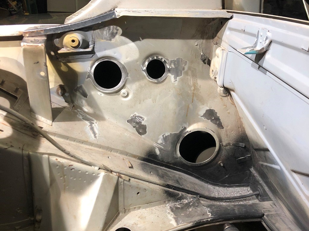 The rubber sleeve for the filter console fits the hole I cut nicely. Do the hard rubber/plastic insulation washers meet through the hole? In other words, do the mounting holes need to be large enough that the stepped mounting washers go through the holes? 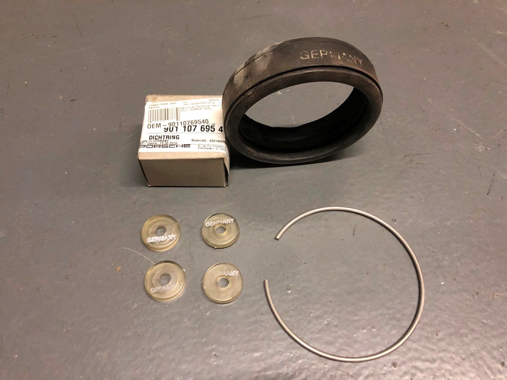 While I like the DW Design filler neck, I wish the screw-on cap looked more like the 914-6 oil fill cap. I may find a donor stock looking cap to modify. I found that the oil filler neck that I thought I had is actually from a 911 and doesn't properly fit the oil tank opening. 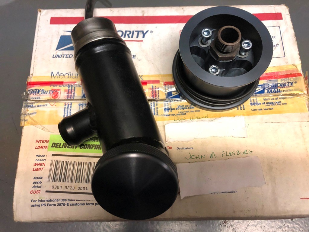 As I'm doing this, I'm wondering about how I will plumb this car. In the past, I've had front mount oil coolers and tanks. I've run the return line from the engine case up front to a thermostat then cooler then back to thermostat, then oil filter, then to tank. I've never plumbed in a pressure relief valve in the external oil cooler circuit. I've noticed that in all the 914-6 GT cars, a pressure relief valve in addition to a thermostat is used. I'm not 100% convinced that I really need the pressure relief valve, but why would they have put them in the GT cars? In air cooled 911 street cars, they simply put a thermostat in the lines leading to/from the front mounted coolers. Any thoughts on the pressure relief valves plumbed into the GT cars? Anyone actually use a pressure relief valve in the lines to the external oil cooler? 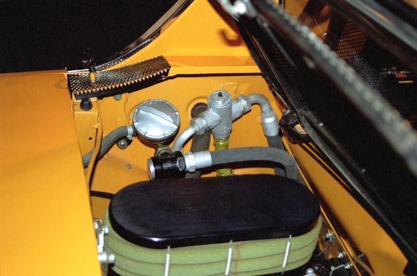 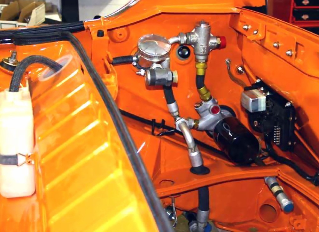 I have decided to relocate the engine lid release latch to the passenger side. I'll keep plugging away at this. |
|
|
|
| mepstein |
Dec 23 2020, 12:03 PM
Post
#74
|
|
914-6 GT in waiting Group: Members Posts: 20,841 Joined: 19-September 09 From: Landenberg, PA/Wilmington, DE Member No.: 10,825 Region Association: MidAtlantic Region |
Eric at PMB has the GT style pressure relief line in his car. It's not used often in these conversions and it's pretty pricy. The parts are similar to a 1969 911S. Reproductions are available but even they are a couple grand. for the whole setup.
I don't normally see the mounting holes drilled for the steps. |
|
|
|
| mb911 |
Dec 23 2020, 03:42 PM
Post
#75
|
|
914 Guru Group: Members Posts: 7,794 Joined: 2-January 09 From: Burlington wi Member No.: 9,892 Region Association: Upper MidWest |
QUOTE(mepstein @ Dec 23 2020, 10:03 AM) Eric at PMB has the GT style pressure relief line in his car. It's not used often in these conversions and it's pretty pricy. The parts are similar to a 1969 911S. Reproductions are available but even they are a couple grand. for the whole setup. I don't normally see the mounting holes drilled for the steps. (IMG:style_emoticons/default/agree.gif) I can source everything original but it really is waste of time |
|
|
|
| John |
Dec 24 2020, 03:43 PM
Post
#76
|
|
member? what's a member? Group: Members Posts: 3,393 Joined: 30-January 04 From: Evansville, IN (SIRPCA) Member No.: 1,615 Region Association: None |
The only reasoning I can come up with for the pressure relief valve would be if the bypass in either the filter console or the filter would fail, either popping the oil cooler or the oil filter. Most modern filters that I know of have a bypass built into them. Some of the racing filters will filter 100% oil all the time, but I'm not using one of those, and the filter console that I have doesn't even have a bypass installed and relies on the bypass of the filter itself. Not installing any of that makes sense to me, and makes plumbing far simpler. I was mainly looking for what others thought.
As far as the stepped washers go, I would assume that the one protruding would mount next to the tank, the recessed one would be in the engine bay covered with one of those large cup washers then a flat washer like on a 911. I'll ask again, how many folks remove the 4-cyl engine mounts? While looking at where I think I'll end up running oil lines, those mounts might just be in the way, so that pretty much answers my own question. Some days it's just tough to keep on-track and motivated. Too many distractions such as it looks like I need new o-rings for the injectors on that 2.7.  I'm still looking for those large cup washers that I swear I bought once upon a time... |
|
|
|
| mepstein |
Dec 24 2020, 04:06 PM
Post
#77
|
|
914-6 GT in waiting Group: Members Posts: 20,841 Joined: 19-September 09 From: Landenberg, PA/Wilmington, DE Member No.: 10,825 Region Association: MidAtlantic Region |
I recently sent Ben an oil filter console just like yours. No bypass valve, just open flow. Do you remember where you purchased yours?
I normally use the regular Porsche console. I remove the threaded metal fitting and use a very small C clamp to hold down the bypass spring so I can make sure it gets cleaned out inside. Then a couple drops of motor oil to make sure it stays functional. Ben/MB911 is making new consoles based off the Porsche design so we won't have to search for good used ones. I have one conversion with 914-4 motor mounts and one without. The one without looks cleaner and has more space for hoses but the other reason was the mounts were rusty so getting in back of them was necessary to clean up the corrosion. |
|
|
|
| John |
Dec 26 2020, 09:28 PM
Post
#78
|
|
member? what's a member? Group: Members Posts: 3,393 Joined: 30-January 04 From: Evansville, IN (SIRPCA) Member No.: 1,615 Region Association: None |
QUOTE(mepstein @ Dec 24 2020, 02:06 PM) I recently sent Ben an oil filter console just like yours. No bypass valve, just open flow. Do you remember where you purchased yours? I normally use the regular Porsche console. I remove the threaded metal fitting and use a very small C clamp to hold down the bypass spring so I can make sure it gets cleaned out inside. Then a couple drops of motor oil to make sure it stays functional. Ben/MB911 is making new consoles based off the Porsche design so we won't have to search for good used ones. I have one conversion with 914-4 motor mounts and one without. The one without looks cleaner and has more space for hoses but the other reason was the mounts were rusty so getting in back of them was necessary to clean up the corrosion. I think the filler neck and the filter console both came from Don Welch 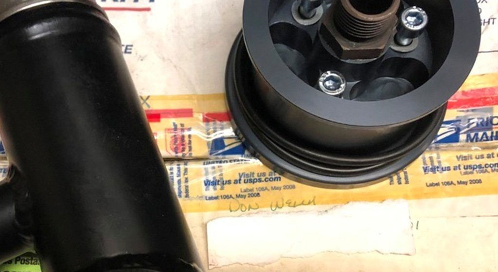 I remember now why I was reluctant to remove the 4-cyl mounts, such a pain in the butt, but I'm glad I did as this is the first rust I've found, but it was just surface rust. I plan on welding in that piece of one of the old chassis stiffening kits now that the old engine mount is removed. Not sure it's really needed, but while I am in there... 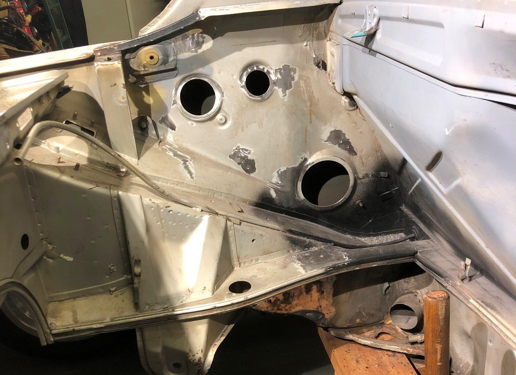 I guess now I must do the other side. Once it's done, I'll be glad I did as it is cleaner that way. |
|
|
|
|
1 User(s) are reading this topic (1 Guests and 0 Anonymous Users)
0 Members:

|
Lo-Fi Version | Time is now: 29th July 2026 - 07:52 AM |
Invision Power Board
v9.1.4 © 2026 IPS, Inc.