|
|
|
Porsche, and the Porsche crest are registered trademarks of Dr. Ing. h.c. F. Porsche AG.
This site is not affiliated with Porsche in any way. Its only purpose is to provide an online forum for car enthusiasts. All other trademarks are property of their respective owners. |
|
|

  |

| FL000 |
 Jan 10 2021, 11:01 AM Jan 10 2021, 11:01 AM
Post
#101
|
|
Member  Group: Members Posts: 481 Joined: 31-January 12 From: Lancaster, CA Member No.: 14,076 Region Association: Southern California |
QUOTE(cali914 @ Jan 9 2021, 11:29 PM)  You are lucky from the head situation and the accident. Get a edelbrock programmable fuel injection kit and you will be so happy. I am seriously considering the Edlebrock Pro Flo 4. I am fairly sure having an untuned carb and timing off messed my heads up. I need something with an ECU to help make that stuff easy for me. Went back and forth on LS, Audi twin turbo, and others but staying the course on SBC for now. Money is part of it (debatable on how much more/less to go these routes) but mainly it boiled down to getting it back on the road as soon as possible. Not sure I can handle a 1-2 year project and just want to drive (IMG:style_emoticons/default/driving.gif) |
   |

 
|
| FL000 |
Jan 10 2021, 11:18 AM
Post
#102
|
|
Member Group: Members Posts: 481 Joined: 31-January 12 From: Lancaster, CA Member No.: 14,076 Region Association: Southern California |
QUOTE(Andyrew @ Jan 9 2021, 11:33 PM) Hopefully the damages are just the oil pan?? Wish I had the oil pan on it (IMG:style_emoticons/default/biggrin.gif) The crank pulley and one of the crankshaft counter weights took the brunt of the impact. Engine landed on the stand first which was more forgiving than straight concrete. Other than the tiniest marks on those areas, nothing visibly broken. With a cast crank who knows if it was damaged seriously and what will happen when I fire it up. Rotating assembly still turns smooth, and going to press on ahead since I don’t want to drop more money into this block. It will still be fine for getting my trans mounted and all the tidbits that go along with that. Then I can figure out the longer term replacement for this engine. |
|
|
|
| djway |
Jan 10 2021, 12:36 PM
Post
#103
|
|
Senior Member Group: Members Posts: 787 Joined: 16-October 15 From: Riverside Member No.: 19,266 Region Association: Southern California |
If it was welded it doesn’t look like the weld penetrated so essentially it wasn’t welded.
That should be brought to their attention. |
|
|
|
| FL000 |
Jan 10 2021, 01:36 PM
Post
#104
|
|
Member Group: Members Posts: 481 Joined: 31-January 12 From: Lancaster, CA Member No.: 14,076 Region Association: Southern California |
QUOTE(djway @ Jan 10 2021, 10:36 AM) If it was welded it doesn’t look like the weld penetrated so essentially it wasn’t welded. That should be brought to their attention. Good call, reported it at saferproducts.gov A quick google search turned up empty so maybe this was a one off occurrence, but who knows. |
|
|
|
| FL000 |
Jan 11 2021, 09:27 PM
Post
#105
|
|
Member Group: Members Posts: 481 Joined: 31-January 12 From: Lancaster, CA Member No.: 14,076 Region Association: Southern California |
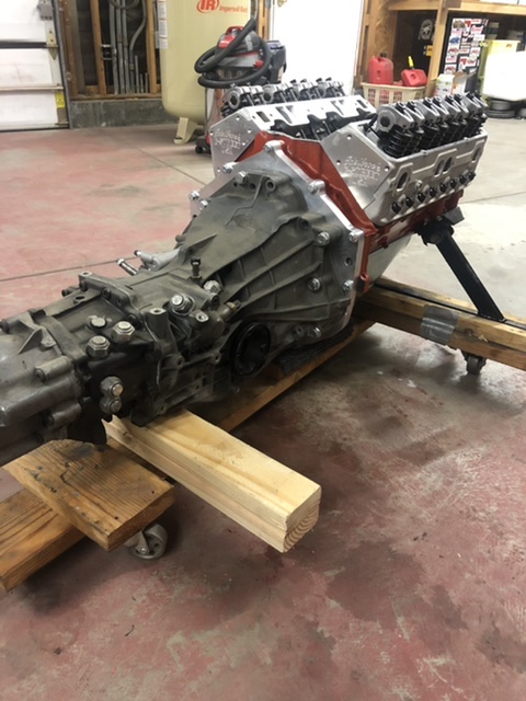
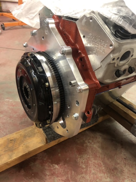
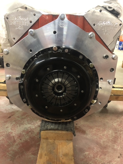
Alright back to happier times. Got the 01E mounted to the engine. Will probably come half a dozen more times but feels good seeing them together.
   |
|
|
|
| djway |
Jan 12 2021, 01:26 AM
Post
#106
|
|
Senior Member Group: Members Posts: 787 Joined: 16-October 15 From: Riverside Member No.: 19,266 Region Association: Southern California |
QUOTE(FL 000 @ Jan 11 2021, 07:27 PM) Alright back to happier times. Got the 01E mounted to the engine. Will probably come half a dozen more times but feels good seeing them together. PURDY |
|
|
|
| cali914 |
Jan 12 2021, 11:19 AM
Post
#107
|
|
cali914 Group: Members Posts: 459 Joined: 26-April 06 From: Berkeley Ca. Member No.: 5,934 Region Association: Northern California |
nice
|
|
|
|
| tygaboy |
Jan 12 2021, 12:40 PM
Post
#108
|
|
914 Guru Group: Members Posts: 5,827 Joined: 6-October 15 From: Petaluma, CA Member No.: 19,241 Region Association: Northern California |
(IMG:style_emoticons/default/agree.gif)
Great to see things going back together! (IMG:style_emoticons/default/cheer.gif) |
|
|
|
| FL000 |
Jan 24 2021, 07:26 PM
Post
#109
|
|
Member Group: Members Posts: 481 Joined: 31-January 12 From: Lancaster, CA Member No.: 14,076 Region Association: Southern California |
Calling all (IMG:style_emoticons/default/welder.gif) out there. Modifying my gas tank for an internal fuel pump and got it this far. Looks fairly good to the eye.
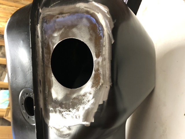 Then shine a light behind it and see this all around the patch 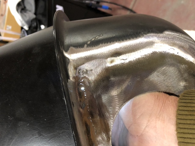 What’s the next step? Keep chasing each hole down with MIG? Switch to TIG? Is there something I can just coat it with and call it a day (only partially joking). The metal is pretty thin and worried about getting into a cycle of tacking, sanding, and continuing to burn through the ever thinning metal. Thanks |
|
|
|
| 76-914 |
Jan 25 2021, 08:38 AM
Post
#110
|
|
Repeat Offender & Resident Subaru Antagonist Group: Members Posts: 13,898 Joined: 23-January 09 From: Temecula, CA Member No.: 9,964 Region Association: Southern California |
QUOTE(FL 000 @ Jan 24 2021, 05:26 PM) Calling all (IMG:style_emoticons/default/welder.gif) out there. Modifying my gas tank for an internal fuel pump and got it this far. Looks fairly good to the eye. Then shine a light behind it and see this all around the patch What’s the next step? Keep chasing each hole down with MIG? Switch to TIG? Is there something I can just coat it with and call it a day (only partially joking). The metal is pretty thin and worried about getting into a cycle of tacking, sanding, and continuing to burn through the ever thinning metal. Thanks You can buy a repro from Pelican for ~ $200. (IMG:style_emoticons/default/beerchug.gif) |
|
|
|
| tygaboy |
Jan 25 2021, 09:15 AM
Post
#111
|
|
914 Guru Group: Members Posts: 5,827 Joined: 6-October 15 From: Petaluma, CA Member No.: 19,241 Region Association: Northern California |
When I welded on my tank:
Go with TIG, very sharp, longer than normal taper length on the tungsten, very thin filler rod, perhaps even MIG wire. You're after the smallest HAZ possible. I didn't use the following technique on the tank in my pic but: Tape over all the openings leaving room to insert a shop vac hose in one of them. Put a sock or something over the end of the hose and leave enough room around the hose so that when the vac is on, you're creating a SLIGHT vacuum inside the tank. Yes, this is very unscientific, but... The vacuum causes the weld puddle to pull inward and leaves less weld material sitting higher than the parent layer that requires grinding. YMMV. Hope this helps. Attached thumbnail(s) 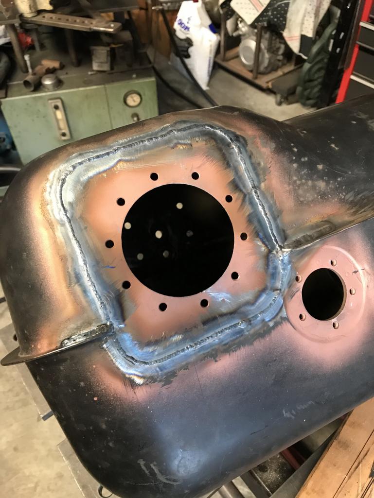
|
|
|
|
| FL000 |
Jan 25 2021, 05:50 PM
Post
#112
|
|
Member Group: Members Posts: 481 Joined: 31-January 12 From: Lancaster, CA Member No.: 14,076 Region Association: Southern California |
QUOTE(76-914 @ Jan 25 2021, 06:38 AM) Hey Kent, forgot to mention this is a reproduction tank I got from parts geek for ~$200. I decided to cut a large section out of the top to remove the internal baffle and make room for my new pump/baffle. I’ll show a few pics of what I did in a bit. |
|
|
|
| FL000 |
Jan 25 2021, 05:59 PM
Post
#113
|
|
Member Group: Members Posts: 481 Joined: 31-January 12 From: Lancaster, CA Member No.: 14,076 Region Association: Southern California |
QUOTE(tygaboy @ Jan 25 2021, 07:15 AM) When I welded on my tank: Go with TIG, very sharp, longer than normal taper length on the tungsten, very thin filler rod, perhaps even MIG wire. You're after the smallest HAZ possible. I didn't use the following technique on the tank in my pic but: Tape over all the openings leaving room to insert a shop vac hose in one of them. Put a sock or something over the end of the hose and leave enough room around the hose so that when the vac is on, you're creating a SLIGHT vacuum inside the tank. Yes, this is very unscientific, but... The vacuum causes the weld puddle to pull inward and leaves less weld material sitting higher than the parent layer that requires grinding. YMMV. Hope this helps. Thanks Chris, and I do plan to use the vacuum technique. I used it on my first patch attempt but I messed up the patch so bad (not due to vacuum) that I decided to cut it out and try again. This is my second attempt with a new welder, and although skill is probably more important than machine I am having much better luck (IMG:style_emoticons/default/welder.gif) (IMG:style_emoticons/default/smash.gif) (IMG:style_emoticons/default/sawzall-smiley.gif) I got some silicon bronze tig rods too and may just try brazing the rest since I am just trying to cover pin holes at this point. New to TIG and will play around with the sharpening as you mentioned also (IMG:style_emoticons/default/beerchug.gif) |
|
|
|
| Rider914 |
Jan 26 2021, 12:22 PM
Post
#114
|
|
Member Group: Members Posts: 276 Joined: 13-April 04 From: Palm Beach Member No.: 1,923 |
QUOTE(rhodyguy @ Jan 8 2021, 11:13 PM) WOW! That could have been a life changing event. Sorry for the hassle. It'll work out. As bad as that went, it couldn't have gone any better... Unfortunately, I have had to tell myself that many times over the years. |
|
|
|
| FL000 |
Mar 6 2021, 01:04 PM
Post
#115
|
|
Member Group: Members Posts: 481 Joined: 31-January 12 From: Lancaster, CA Member No.: 14,076 Region Association: Southern California |
QUOTE(Rider914 @ Jan 26 2021, 10:22 AM) QUOTE(rhodyguy @ Jan 8 2021, 11:13 PM) WOW! That could have been a life changing event. Sorry for the hassle. It'll work out. As bad as that went, it couldn't have gone any better... Unfortunately, I have had to tell myself that many times over the years. Definitely a good way to approach it! Feel exactly the same way. |
|
|
|
| FL000 |
Mar 6 2021, 01:17 PM
Post
#116
|
|
Member Group: Members Posts: 481 Joined: 31-January 12 From: Lancaster, CA Member No.: 14,076 Region Association: Southern California |
Haven’t posted in awhile but have been busy. Unfortunately working like 4 different things at same time so not much finished.
I did declare victory on the tank though. After multiple weld/grind/inspect cycles experimenting with MIG/TIG/brazing I got the top to only have a few remaining pinholes. Was mainly worried about slosh so put a finish coat of JB weld on it and sanded smooth to paint. 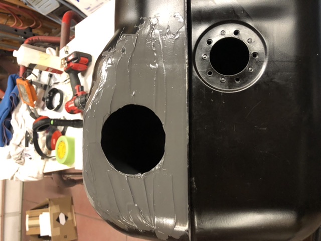 I wanted the bottom pinhole free with metal and muggy weld solder rods were what finally did the trick. Low enough temp that I was able to use heat gun and wicking allowed the solder to flow into the remaining holes. Didn’t attempt pushing my luck and sanding smooth so once I knew the leaks were gone I just painted it. 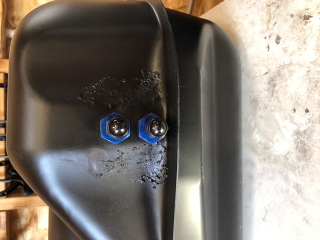 Relocated cap to driver side and basically have it setup like @tygaboy did on his; why reinvent the wheel when I can just capitalize on everyone’s trial and error and good ideas (IMG:style_emoticons/default/smile.gif) 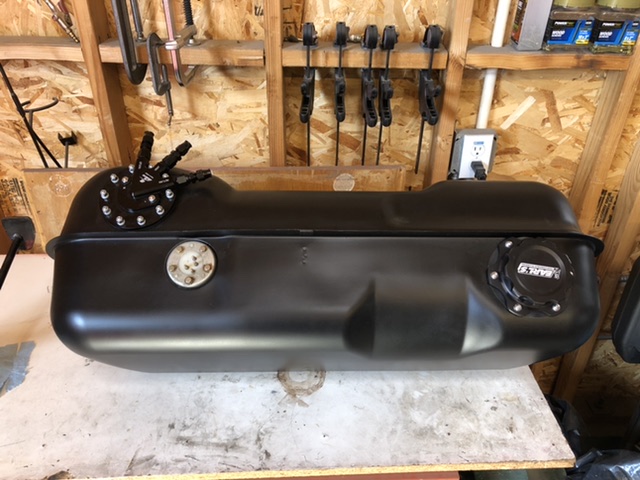 |
|
|
|
| FL000 |
Mar 6 2021, 01:28 PM
Post
#117
|
|
Member Group: Members Posts: 481 Joined: 31-January 12 From: Lancaster, CA Member No.: 14,076 Region Association: Southern California |
Also making progress on the clutch master cylinder. Wow it is tight adding a clutch master cylinder next to brake master but @dwillouby took the guess work out with his bracket kit.
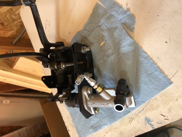 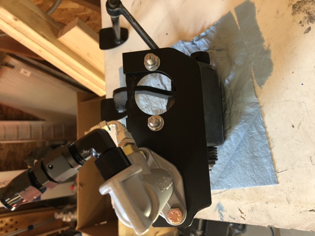 I rounded the corners to remove some excess material and to give the radiator hose something smooth to rest on. I am going to use 3/8” aluminum tube from the M/C up behind tank and then transition to rubber hose for final connection to reservoir. Apologies for rotated pics but doing this in car while daughter is getting horseback lessons and not in the mood to fight it! |
|
|
|
| FL000 |
Mar 6 2021, 01:36 PM
Post
#118
|
|
Member Group: Members Posts: 481 Joined: 31-January 12 From: Lancaster, CA Member No.: 14,076 Region Association: Southern California |
Here are some from under and above the pedal cluster. Following what @76-914 and others have done with a few deviations here and there.
 The blue inlet fitting points right at the steering shaft so I swapped that out for a 90 degree fitting. 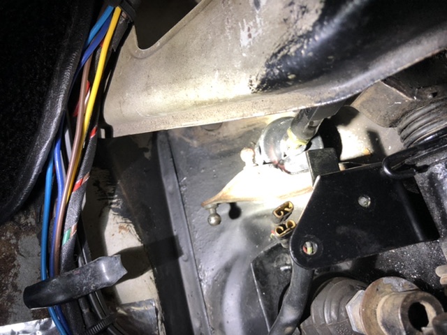 A little bit of glare from flashlight but you can see I grounded some of the accelerator linkage off to make sure it clears the clutch master bushing. Nothing scarier than letting off the gas and the car doesn’t respond (IMG:style_emoticons/default/blink.gif) been there done that. |
|
|
|
| FL000 |
Mar 6 2021, 01:51 PM
Post
#119
|
|
Member Group: Members Posts: 481 Joined: 31-January 12 From: Lancaster, CA Member No.: 14,076 Region Association: Southern California |
Nothing new that timing a SBC is a pain in the rear on a 914. Don’t have the best visibility to front of engine and stock timing tab doesn’t fit well either. Yes I know if I was smart and had an LS I wouldn’t have this problem, but maybe someday I will catch on (IMG:style_emoticons/default/lol-2.gif)
To give me the ability to check the timing I am using a factory hole in side of trans at about the 10 o’clock position , viewing from rear - or here (forward most of 2 side by side ones) 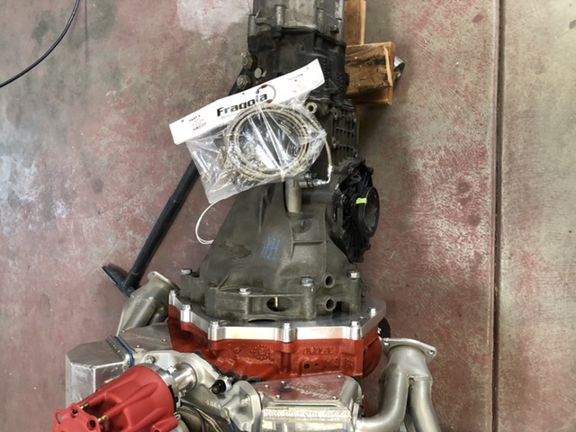 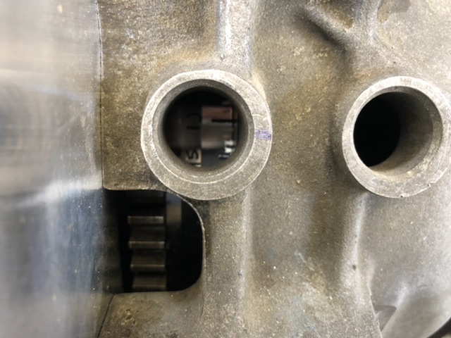 May not show well but I put a number of degree marks on the flywheel using a metal awl and a paint pen. Figured the paint will make it easy to see and the scratches will save the day of paint comes off! Plan to use an old timing light I have, remove light and extend the wire length, and position snake cable style camera and timing light near hole to check when engine is running. Probably easier to see than explain, so will add pics later (if it works) |
|
|
|
| FL000 |
Apr 3 2021, 05:34 PM
Post
#120
|
|
Member Group: Members Posts: 481 Joined: 31-January 12 From: Lancaster, CA Member No.: 14,076 Region Association: Southern California |
Making slow but steady progress. Hard to believe it has been over 4 months since it has been on the road. Need to wrap this up soon.
Wanted to fabricate my cable shifter but didn’t trust my skills, or at least in a timely manner. Went with the Cable Shift setup and pretty happy with it so far. The original adapter on the trans had one cable coming in at an angle that interfered with my trunk pan so I made some modifications. Here it is in a test setup to make sure it works while I still have some room to work on it. 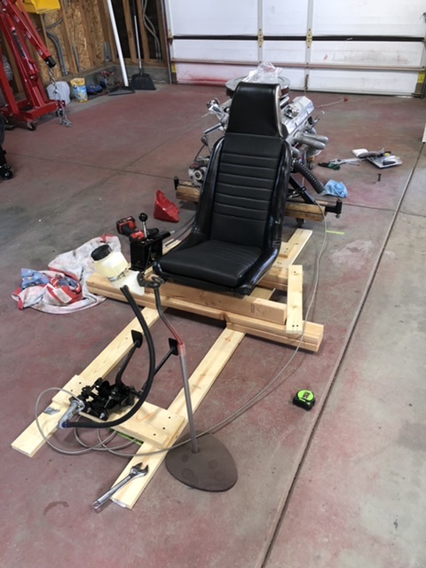 Reminds me of making a go kart as a kid (IMG:style_emoticons/default/smile.gif) 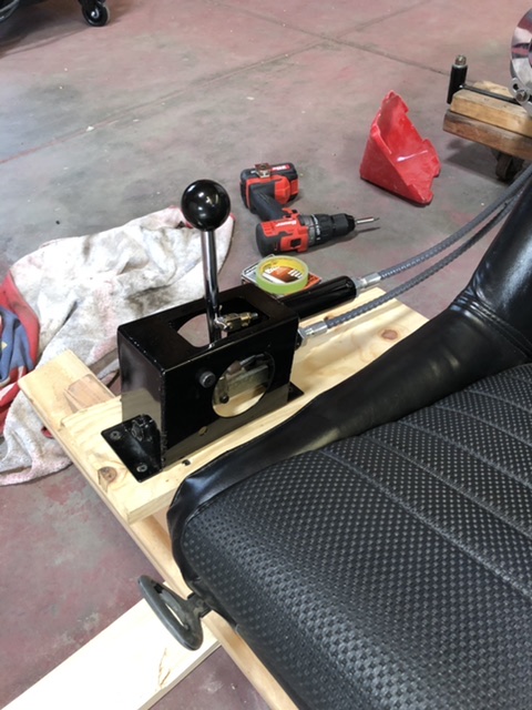 Shifter is a bit industrial for my preferences so I will spruce it up in the car. 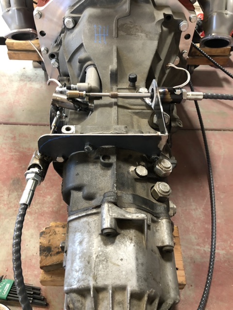 Hydraulic clutch seems to work well and can get into all the gears, except reverse. Not too concerned since i was able to before I mounted the trans to engine. Thinking it can be difficult without engine running. (IMG:style_emoticons/default/idea.gif) |
|
|
|
|
1 User(s) are reading this topic (1 Guests and 0 Anonymous Users)
0 Members:

|
Lo-Fi Version | Time is now: 17th June 2026 - 03:41 AM |
Invision Power Board
v9.1.4 © 2026 IPS, Inc.