|
|
|
Porsche, and the Porsche crest are registered trademarks of Dr. Ing. h.c. F. Porsche AG.
This site is not affiliated with Porsche in any way. Its only purpose is to provide an online forum for car enthusiasts. All other trademarks are property of their respective owners. |
|
|


| Gatornapper |
 Dec 14 2019, 08:40 PM Dec 14 2019, 08:40 PM
Post
#1
|
|
Senior Member  Group: Members Posts: 1,285 Joined: 22-September 17 From: Woods west of Richmond, VA Member No.: 21,449 Region Association: South East States |
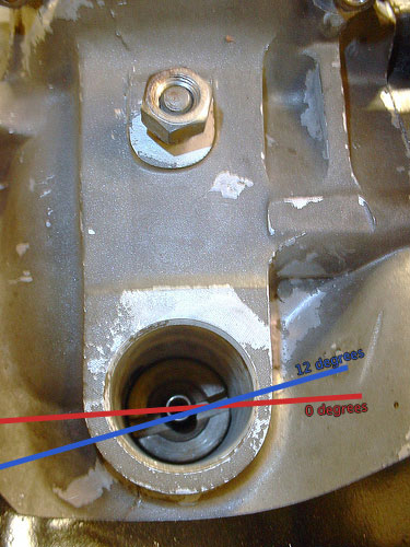
Haynes Manual, page 65, Fig. 3.6, referenced from page 64, Pp. 6, #7: "install it so that.........an angle of 12 deg. .......with the small sector facing towards the outside of the car."
On my 914, the small sector is on the left. If I'm reading this correctly, this is ambiguous and does not clarify it "the outside of the car" is the Driver's side or Passenger side....... Can someone clarify this please? Or am I missing something (not the first time...)..... TIA, GN |
   |

 
|
  |
Replies(1 - 19)
| Garland |
Dec 15 2019, 12:18 AM
Post
#2
|
|
Restoration Fanatic Group: Members Posts: 1,422 Joined: 8-January 04 From: ......Michigan...... Member No.: 1,535 Region Association: Upper MidWest |
|
 |
|
| Gatornapper |
Dec 15 2019, 07:02 AM
Post
#3
|
|
Senior Member Group: Members Posts: 1,285 Joined: 22-September 17 From: Woods west of Richmond, VA Member No.: 21,449 Region Association: South East States |
Thank you.
So, how did mine get about 180 degrees out of sync? Did a large backfire destroy the drive gear? (IMG:http://www.914world.com/bbs2/uploads_offsite/i890.photobucket.com-21449-1576414972.1.jpg) ?????????? QUOTE(Garland @ Dec 15 2019, 01:18 AM)  |
|
|
|
| Gatornapper |
Dec 15 2019, 07:15 AM
Post
#4
|
|
Senior Member Group: Members Posts: 1,285 Joined: 22-September 17 From: Woods west of Richmond, VA Member No.: 21,449 Region Association: South East States |
Thanks Garland.....
Perhaps I'm not on TDC, not on compression stroke - but one rev out... Will check later today...... GN |
|
|
|
| Superhawk996 |
Dec 15 2019, 10:15 AM
Post
#5
|
|
914 Guru Group: Members Posts: 7,573 Joined: 25-August 18 From: Woods of N. Idaho Member No.: 22,428 Region Association: Galt's Gulch |
QUOTE(Gatornapper @ Dec 15 2019, 08:15 AM) Thanks Garland..... Perhaps I'm not on TDC, not on compression stroke - but one rev out... Will check later today...... GN It is not possible for a backfire to destroy the gear interface between the crank and the distributor. Easiest way is to pull valve cover. Look at the valves. When both are closed and you're at TDC you know your on the compression stroke. There is no possibility of being 180 out if both valves are closed. Setting aside all other nonsene of manual, if you set to TDC #1 based on piston and valve position, and then align the distributor into the notches such that the rotor is pointing at Cylinder #1 spark plug terminal, it will be correct. |
|
|
|
| Gatornapper |
Dec 15 2019, 12:37 PM
Post
#6
|
|
Senior Member Group: Members Posts: 1,285 Joined: 22-September 17 From: Woods west of Richmond, VA Member No.: 21,449 Region Association: South East States |
Ok, #1 is at TDC, and this is the position of the rotor - between cap towers - not under a tower. Because of the off-set on the groove in the dist shaft and the dist. base, this is the only way it will go in.
This is also with the points set by static timing immediately after light went on, slowly turning dizzy CCW......i.e., dizzy was inserted initially with point of rotor on mark on top wall of dizzy, and has been rotated CCW from that point. Splines of dizzy base are fully inserted in shaft. (IMG:http://www.914world.com/bbs2/uploads_offsite/i890.photobucket.com-21449-1576435456.1.jpg) How can this be? If I remember correctly, when engine was running well, the #1 cap tower was at about 11 o'clock from the rear facing the front of the car. About 80 deg. CCW from where it is now......... What changed it's orientation? GN |
|
|
|
| sixnotfour |
Dec 15 2019, 12:43 PM
Post
#7
|
|
914 Wizard Group: Members Posts: 11,060 Joined: 12-September 04 From: Life Elevated..planet UT. Member No.: 2,744 Region Association: Rocky Mountains |
non bosch rotor make sure it actually is push into the notch on the shaft...pull off and double check..
|
|
|
|
| Gatornapper |
Dec 15 2019, 12:47 PM
Post
#8
|
|
Senior Member Group: Members Posts: 1,285 Joined: 22-September 17 From: Woods west of Richmond, VA Member No.: 21,449 Region Association: South East States |
QUOTE(sixnotfour @ Dec 15 2019, 01:43 PM) non bosch rotor make sure it actually is push into the notch on the shaft...pull off and double check.. Done. Will put Bosche rotor back on. |
|
|
|
| Garland |
Dec 15 2019, 01:04 PM
Post
#9
|
|
Restoration Fanatic Group: Members Posts: 1,422 Joined: 8-January 04 From: ......Michigan...... Member No.: 1,535 Region Association: Upper MidWest |
Are you sure you’re getting the distributor housing, passed the hold down clamp, and seated to the block?
|
|
|
|
| Superhawk996 |
Dec 15 2019, 01:06 PM
Post
#10
|
|
914 Guru Group: Members Posts: 7,573 Joined: 25-August 18 From: Woods of N. Idaho Member No.: 22,428 Region Association: Galt's Gulch |
QUOTE(Gatornapper @ Dec 15 2019, 01:37 PM) This is also with the points set by static timing immediately after light went on, slowly turning dizzy CCW......i.e., dizzy was inserted initially with point of rotor on mark on top wall of dizzy, and has been rotated CCW from that point. @Gatornapper I'm a bit confused by your statement that you set static timing immediately after the light went ON. Your test light should be fed by +12v. The ground circuit is completed by the points. When the points are closed, the light is ON. Static timing is set by rotating the distributor until the light goes OFF and the points have just begun to OPEN. The ignigiton fires off spark when the points OPEN. Thus, the point at which the light turns OFF is what you're intested in when setting the static timing. |
|
|
|
| Superhawk996 |
Dec 15 2019, 01:41 PM
Post
#11
|
|
914 Guru Group: Members Posts: 7,573 Joined: 25-August 18 From: Woods of N. Idaho Member No.: 22,428 Region Association: Galt's Gulch |
QUOTE(Superhawk996 @ Dec 15 2019, 02:06 PM) QUOTE(Gatornapper @ Dec 15 2019, 01:37 PM) This is also with the points set by static timing immediately after light went on, slowly turning dizzy CCW......i.e., dizzy was inserted initially with point of rotor on mark on top wall of dizzy, and has been rotated CCW from that point. @Gatornapper I'm a bit confused by your statement that you set static timing immediately after the light went ON. Your test light should be fed by +12v. The ground circuit is completed by the points. When the points are closed, the light is ON. Static timing is set by rotating the distributor until the light goes OFF and the points have just begun to OPEN. The ignigiton fires off spark when the points OPEN. Thus, the point at which the light turns OFF is what you're intested in when setting the static timing. Note: As I thought about this more, you could configure the light to work either way depending on how you wired the light in. The method above is what has always worked for me where I use the points to break the circuit and turn the light OFF. Actually, I don't even use a light. I just measure the resistance across the points with a DMM but the principle is the same. Regarless, the coil always fires off the spark when the point open. |
|
|
|
| rjames |
Dec 15 2019, 02:25 PM
Post
#12
|
|
I'm made of metal Group: Members Posts: 4,412 Joined: 24-July 05 From: Shoreline, WA Member No.: 4,467 Region Association: Pacific Northwest |
Maybe I’m missing something... Is the rotor is pointing at #1 when it is tdc? If yes, tighten the dizzy, but not too tight. From there, check that the points gap is correct.
Set the dwell 44-45 degrees and you are ready to start the car and then set dynamic timing. Points and dwell must be set right for the car to start. There is also a mark on the flywheel that you can see from engine bay that indicates tdc for #1 if you pry back the engine tin/seal a bit. |
|
|
|
| Gatornapper |
Dec 15 2019, 07:27 PM
Post
#13
|
|
Senior Member Group: Members Posts: 1,285 Joined: 22-September 17 From: Woods west of Richmond, VA Member No.: 21,449 Region Association: South East States |
SH -
MY BAD! My brain was not plugged in yesterday and the part that was plugged in was dyslexic! I knew all that, but wasn't thinking clearly. Had just a few minutes today to set points correctly, and rotor is directly under tower to #1, which, facing the front of the car and the firewall is between 1 and 2 o'clock on the dist. cap. with the engine on TDC. Will attempt to start tomorrow....too busy today..... Thanks for pointing out my gross error. Sometimes I'm an idiot. GN QUOTE(Superhawk996 @ Dec 15 2019, 02:06 PM) QUOTE(Gatornapper @ Dec 15 2019, 01:37 PM) This is also with the points set by static timing immediately after light went on, slowly turning dizzy CCW......i.e., dizzy was inserted initially with point of rotor on mark on top wall of dizzy, and has been rotated CCW from that point. @Gatornapper I'm a bit confused by your statement that you set static timing immediately after the light went ON. Your test light should be fed by +12v. The ground circuit is completed by the points. When the points are closed, the light is ON. Static timing is set by rotating the distributor until the light goes OFF and the points have just begun to OPEN. The ignigiton fires off spark when the points OPEN. Thus, the point at which the light turns OFF is what you're intested in when setting the static timing. |
|
|
|
| Gatornapper |
Dec 15 2019, 07:34 PM
Post
#14
|
|
Senior Member Group: Members Posts: 1,285 Joined: 22-September 17 From: Woods west of Richmond, VA Member No.: 21,449 Region Association: South East States |
Thanks!
I have previously marked the following on both the front side of the impeller where you can see it and the flywheel: TDC (black), 7.5 deg. BTDC (white), and 27 deg. BTDC (red). GN QUOTE(rjames @ Dec 15 2019, 03:25 PM) Maybe I’m missing something... Is the rotor is pointing at #1 when it is tdc? If yes, tighten the dizzy, but not too tight. From there, check that the points gap is correct. Set the dwell 44-45 degrees and you are ready to start the car and then set dynamic timing. Points and dwell must be set right for the car to start. There is also a mark on the flywheel that you can see from engine bay that indicates tdc for #1 if you pry back the engine tin/seal a bit. |
|
|
|
| cary |
Dec 16 2019, 12:47 AM
Post
#15
|
|
Advanced Member Group: Members Posts: 3,900 Joined: 26-January 04 From: Sherwood Oregon Member No.: 1,608 Region Association: Pacific Northwest |
You got this. When you are CERTAIN you are at TDC on #1 re orient the dizzy drive. With McMark's 12 degree image you'll have #1 back in the 1 o'clock position.
Three pieces come out. Spring. Dizzy Drive, most important the oiler washer. McMark's write up is outstanding. Superhawk996 Easiest way is to pull valve cover. Look at the valves. When both are closed and you're at TDC you know your on the compression stroke. There is no possibility of being 180 out if both valves are closed. http://www.914world.com/bbs2/index.php?s=&...st&p=105399 |
|
|
|
| 914_teener |
Dec 16 2019, 10:37 AM
Post
#16
|
|
914 Guru Group: Members Posts: 5,268 Joined: 31-August 08 From: So. Cal Member No.: 9,489 Region Association: Southern California |
QUOTE(cary @ Dec 15 2019, 10:47 PM) You got this. When you are CERTAIN you are at TDC on #1 re orient the dizzy drive. With McMark's 12 degree image you'll have #1 back in the 1 o'clock position. Three pieces come out. Spring. Dizzy Drive, most important the oiler washer. McMark's write up is outstanding. Superhawk996 Easiest way is to pull valve cover. Look at the valves. When both are closed and you're at TDC you know your on the compression stroke. There is no possibility of being 180 out if both valves are closed. http://www.914world.com/bbs2/index.php?s=&...st&p=105399 Clean out the dizzy bore. It's a clearance fit but that gunk you've got on the case could be problematic. Just sayin. |
|
|
|
| Gatornapper |
Dec 16 2019, 08:58 PM
Post
#17
|
|
Senior Member Group: Members Posts: 1,285 Joined: 22-September 17 From: Woods west of Richmond, VA Member No.: 21,449 Region Association: South East States |
Like some help checking my reasoning here:
Dizzy rotates 1/2 rotation per each full rotation of crankshaft. On dizzy driveshaft ("DD"), if TDC mark is seen on flywheel or impeller in the notch, and the slot in the DD has the small segment on the right, and is at 12 deg. CCW of vertical, the DD is in the TDC for the compression/fire stroke....as in Garland's Post 2. OTOH, if the TDC mark is seen on the flywheel or impeller in the notch, the slot on the DD will still be 12 deg. CCW of vertical, but the small segment will be on the LEFT side of the DD.....as in my Post 3. But the TDC will be for the exhaust stroke - not the fire stroke. Correct? |
|
|
|
| injunmort |
Dec 17 2019, 06:09 PM
Post
#18
|
|
Senior Member Group: Members Posts: 1,024 Joined: 12-April 10 From: sugarloaf ny Member No.: 11,604 Region Association: North East States |
in your picture, you are not timed on #1. that is #4. #1 from the back of the car is trans left side. 1 next to it is 2(by chimney left side, 3 trans right side , 4 is chimney , right side. by that pic you are 180 out. can be done with better grasp of system. go by book. put #1 on tdc compression (both rockers on #1 loose) check your fan mark, should be in aperture. clock your dist so that the rotor is pointed at the #1 spark plug. you may need to take out drive pinion and turn it 180 degrees. now set points by rotating dist. until points just break. that is it. next is setting with light while running.
|
|
|
|
| rhodyguy |
Dec 17 2019, 06:51 PM
Post
#19
|
|
Chimp Sanctuary NW. Check it out. Group: Members Posts: 22,252 Joined: 2-March 03 From: Orion's Bell. The BELL! Member No.: 378 Region Association: Galt's Gulch |
If the engine is at TDC on #1, and the dist drive is out 180*, for sure, then if you install the distributor, where ever the rotor is pointing would be #1 TDC. Mark that spot on the distributor body lip. If the drive is out 180* the wires are off 180*. The cap only goes on one way.
|
|
|
|
| Gatornapper |
Dec 18 2019, 10:02 AM
Post
#20
|
|
Senior Member Group: Members Posts: 1,285 Joined: 22-September 17 From: Woods west of Richmond, VA Member No.: 21,449 Region Association: South East States |
That was old pic, I realized it was incorrect. It has been corrected. Thought I had stated that.
Rotor now on #1. With #1 on TDC compression stroke. Did static timing at that point, but engine still will not start. QUOTE(injunmort @ Dec 17 2019, 07:09 PM) in your picture, you are not timed on #1. that is #4. #1 from the back of the car is trans left side. 1 next to it is 2(by chimney left side, 3 trans right side , 4 is chimney , right side. by that pic you are 180 out. can be done with better grasp of system. go by book. put #1 on tdc compression (both rockers on #1 loose) check your fan mark, should be in aperture. clock your dist so that the rotor is pointed at the #1 spark plug. you may need to take out drive pinion and turn it 180 degrees. now set points by rotating dist. until points just break. that is it. next is setting with light while running. |
|
|
|
|
2 User(s) are reading this topic (2 Guests and 0 Anonymous Users)
0 Members:

|
Lo-Fi Version | Time is now: 7th December 2025 - 06:45 PM |
Invision Power Board
v9.1.4 © 2025 IPS, Inc.