|
|
|
Porsche, and the Porsche crest are registered trademarks of Dr. Ing. h.c. F. Porsche AG.
This site is not affiliated with Porsche in any way. Its only purpose is to provide an online forum for car enthusiasts. All other trademarks are property of their respective owners. |
|
|

  |

| JamesM |
 Dec 24 2019, 01:33 AM Dec 24 2019, 01:33 AM
Post
#21
|
|
Advanced Member  Group: Members Posts: 2,282 Joined: 6-April 06 From: Kearns, UT Member No.: 5,834 Region Association: Intermountain Region |
QUOTE(Montreal914 @ Dec 23 2019, 10:12 PM)  Based on what you said, I will not use the ICV in the beginning. check. I will order a second MAP immediately. check. I already have an AEM wideband O2 sensor that I bought and installed when I built my 2056. Since I have SS heat exchangers and a banana muffler, its location is far from ideal. It's in the tailpipe as close to the muffler as possible... (IMG:style_emoticons/default/dry.gif) If you already bought the ICV there is no harm in using it I was just saying that its a place where you could have saved a few bucks as you should be able to get on fine without it, especially if you still have an original working AAR. Good that you have a wideband already. while the placement isnt ideal you should be able to get by though i suspect you may get some fluctuating readings at idle. I find idle mixture is usually best dialed in by ear though anyways. Bursch mufflers are relatively cheap, especially used and all 4 pipes join before the muffler giving a more ideal place to install a wideband sensor. If you can find one for a cheap price, or even one you could borrow it may be worth it to swap out while tuning. I have one setup specifically for this purpose, if you were closer I would let you run it. Shipping the thing would probably cost more than it is worth. Cant wait to see your system come together. |
   |

 
|
| Montreal914 |
Dec 25 2019, 01:19 PM
Post
#22
|
|
Advanced Member Group: Members Posts: 2,179 Joined: 8-August 10 From: Claremont, CA Member No.: 12,023 Region Association: Southern California |
Merry Christmas everyone (IMG:style_emoticons/default/wreath.gif)
Personal design notes on the TPS bracket design. (IMG:style_emoticons/default/santa_smiley.gif) 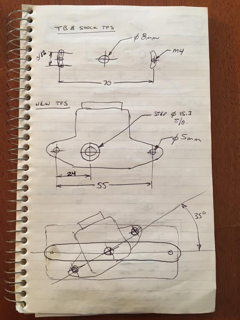 |
|
|
|
| Montreal914 |
Dec 25 2019, 04:43 PM
Post
#23
|
|
Advanced Member Group: Members Posts: 2,179 Joined: 8-August 10 From: Claremont, CA Member No.: 12,023 Region Association: Southern California |
Took a few minutes today to prepare the tool to install the BMW Cylinder head temp sensor. (IMG:style_emoticons/default/smash.gif)
I got a 14mm long reach socket from my local FLAPS and made a slot with my thin disk grinder and Dremel tool. This will allow the wire to go through as shown in the second picture. Then I tried it on the cylinder head. You can also see my ring style type K thermocouple under the #3 spark plug for my cylinder head temperature gauge. Note that this CHT gauge is separate from the whole MS installation. I installed it upon my engine rebuild about 6 years ago for monitoring. 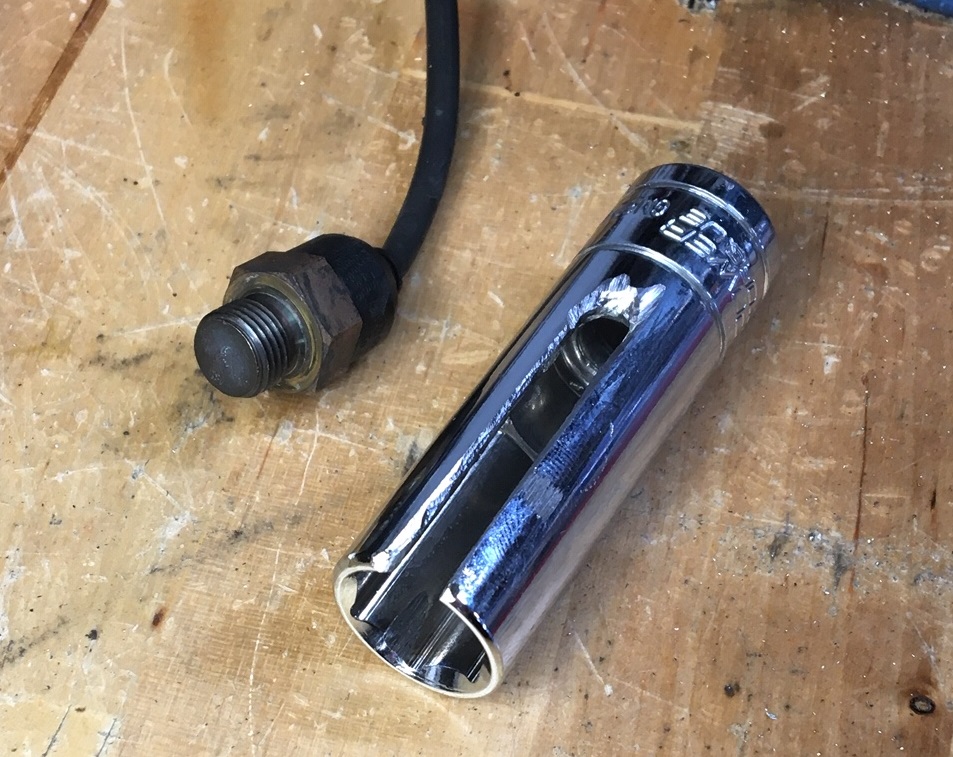 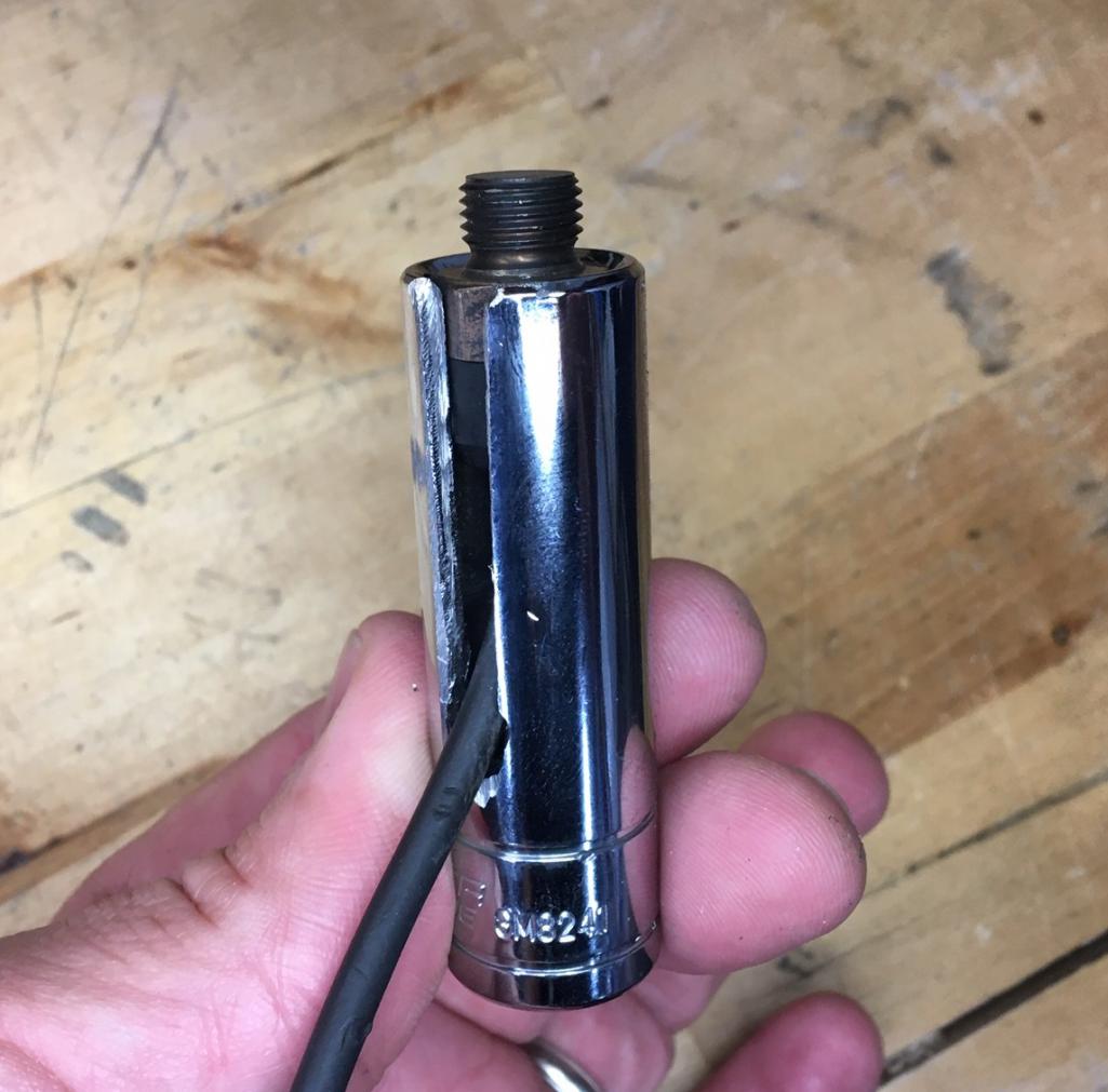 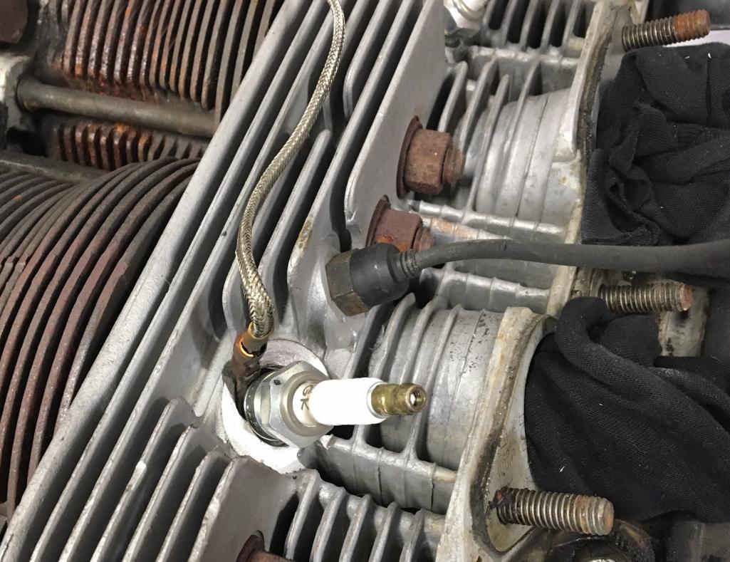 |
|
|
|
| Montreal914 |
Dec 30 2019, 11:04 PM
Post
#24
|
|
Advanced Member Group: Members Posts: 2,179 Joined: 8-August 10 From: Claremont, CA Member No.: 12,023 Region Association: Southern California |
Just came back from a short trip and this was waiting for me. (IMG:style_emoticons/default/smile.gif)
Per @JamesM recommendations, I got a second GM style 1 bar MAP sensor for the atmospheric pressure monitoring. Amazing to get this delivered to your door in a couple of days for $9.35 all included (IMG:style_emoticons/default/beer3.gif) I guess I will connect this one to the analog input of the system but haven't looked yet. Hopefully, there will be a selection for this MAP sensor. (IMG:style_emoticons/default/confused24.gif) 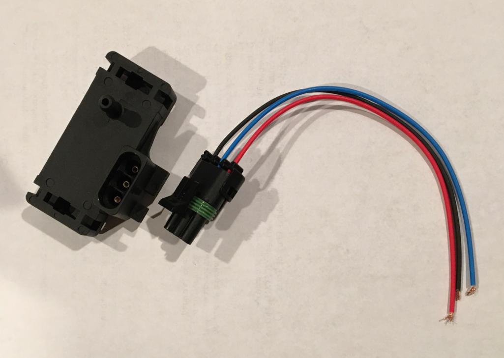 |
|
|
|
| 913B |
Dec 31 2019, 01:35 AM
Post
#25
|
|
Senior Member Group: Members Posts: 881 Joined: 25-April 05 From: South Bay/SoCal Member No.: 3,983 Region Association: None |
Hi, Could you possibly share the amazon link?
Thanks |
|
|
|
| Montreal914 |
Dec 31 2019, 09:07 AM
Post
#26
|
|
Advanced Member Group: Members Posts: 2,179 Joined: 8-August 10 From: Claremont, CA Member No.: 12,023 Region Association: Southern California |
QUOTE(913B @ Dec 30 2019, 11:35 PM) Hi, Could you possibly share the amazon link? Thanks This part was ordered on Ebay: https://www.ebay.com/itm/New-1-bar-Map-Sens...353.m2749.l2649 |
|
|
|
| JamesM |
Dec 31 2019, 11:24 AM
Post
#27
|
|
Advanced Member Group: Members Posts: 2,282 Joined: 6-April 06 From: Kearns, UT Member No.: 5,834 Region Association: Intermountain Region |
QUOTE(Montreal914 @ Dec 30 2019, 10:04 PM) I guess I will connect this one to the analog input of the system but haven't looked yet. Hopefully, there will be a selection for this MAP sensor. (IMG:style_emoticons/default/confused24.gif) vref and gnd connect to the same wires as your 1st MAP sensor. The signal wire on the 2nd sensor can connect to various inputs depending on what firmware you run. I have been using the "spareADC" port for this. Just be sure whatever you wire it to you then match in your tunerstudio config. 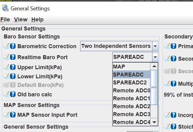 |
|
|
|
| Montreal914 |
Jan 3 2020, 03:47 PM
Post
#28
|
|
Advanced Member Group: Members Posts: 2,179 Joined: 8-August 10 From: Claremont, CA Member No.: 12,023 Region Association: Southern California |
QUOTE(JamesM @ Dec 31 2019, 09:24 AM) QUOTE(Montreal914 @ Dec 30 2019, 10:04 PM) I guess I will connect this one to the analog input of the system but haven't looked yet. Hopefully, there will be a selection for this MAP sensor. (IMG:style_emoticons/default/confused24.gif) vref and gnd connect to the same wires as your 1st MAP sensor. The signal wire on the 2nd sensor can connect to various inputs depending on what firmware you run. I have been using the "spareADC" port for this. Just be sure whatever you wire it to you then match in your tunerstudio config. @JamesM , thank you for the input. Here is a screenshot of my ATM pressure MAP setup. Let me know if you see anything that seems wrong. It wouldn't be surprising... (IMG:style_emoticons/default/rolleyes.gif) 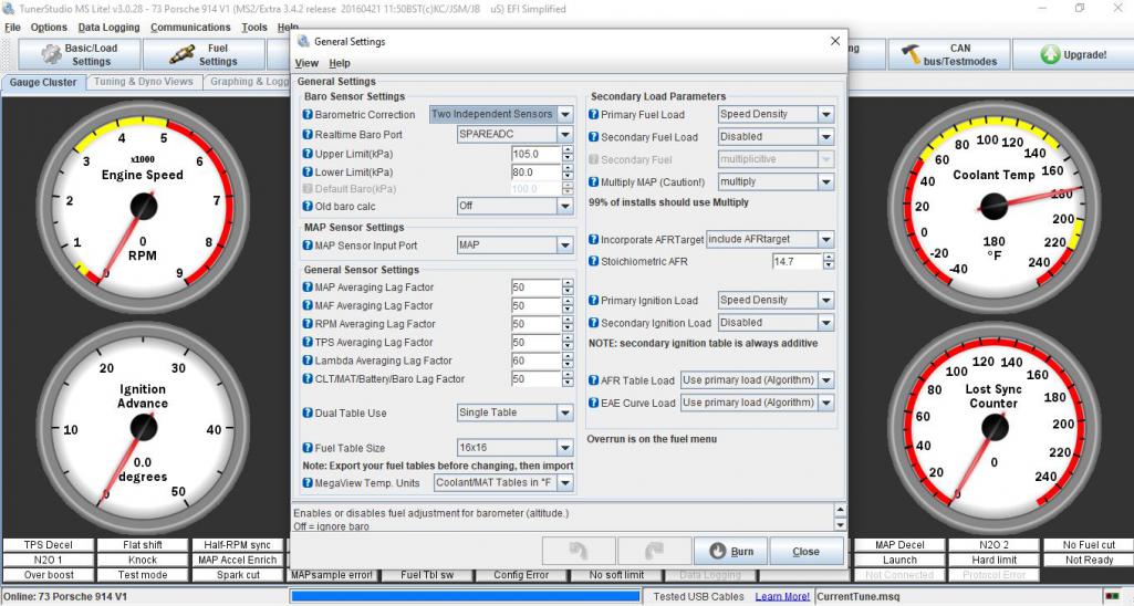 |
|
|
|
| Montreal914 |
Jan 3 2020, 03:55 PM
Post
#29
|
|
Advanced Member Group: Members Posts: 2,179 Joined: 8-August 10 From: Claremont, CA Member No.: 12,023 Region Association: Southern California |
I had a few hours yesterday and today to work on a combined coil and MAP bracket. (IMG:style_emoticons/default/smash.gif)
Since the Distributor will be gone, this combo will be located in that area and the bracket will be secured using the 8mm bolt of the distributor bracket and a couple of engine tin screws of the right side cylinder tin. It will obviously get painted once I am 100% everything fits. Hardware is metric to be consistent... 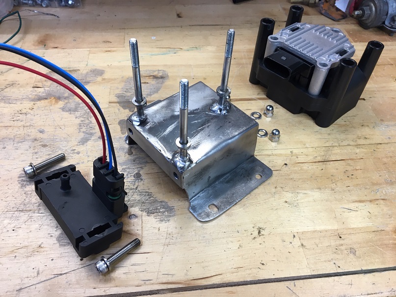 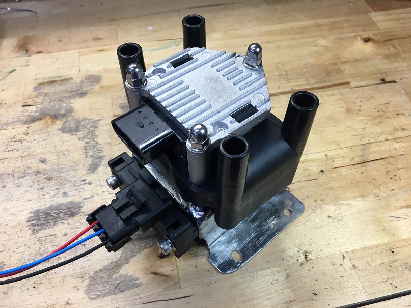 |
|
|
|
| Montreal914 |
Jan 12 2020, 10:27 PM
Post
#30
|
|
Advanced Member Group: Members Posts: 2,179 Joined: 8-August 10 From: Claremont, CA Member No.: 12,023 Region Association: Southern California |
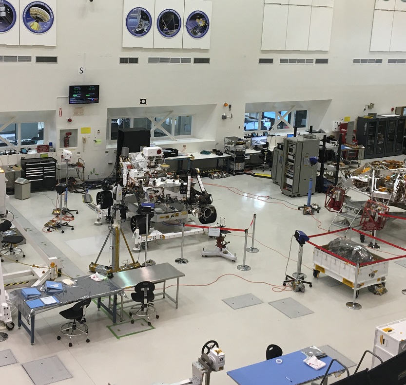
Busy weekend! Took the family to JPL's open doors yesterday to check out the Mars Rover before it leaves for Florida for the launch. (IMG:style_emoticons/default/smile.gif)
 Today I prepared a bracket for the ICV. (IMG:style_emoticons/default/smash.gif) Even though I don't intend to connect it initially (per JamesM recommendation (IMG:style_emoticons/default/beerchug.gif) ), I will eventually. I got the aftermarket BMW rubber mount and used an aluminum plate to make a bracket that will mount on the M6 coil mounting points on the cooling tin. 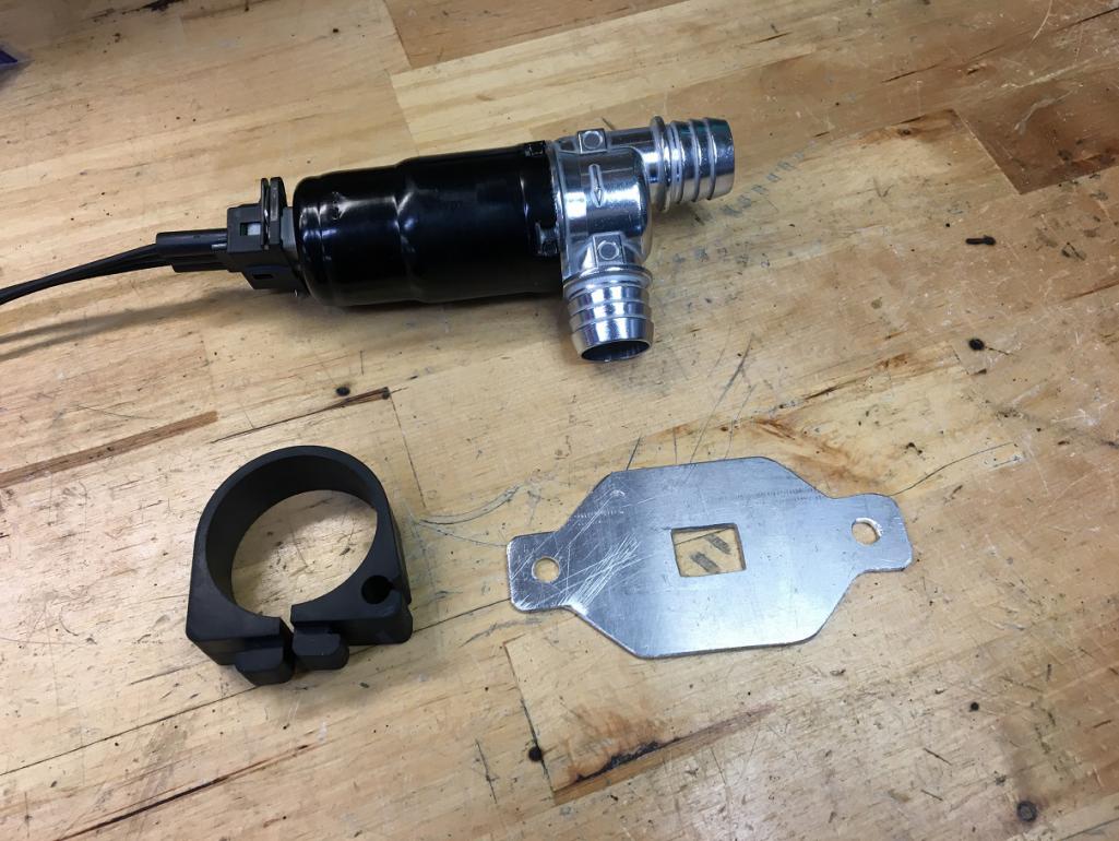 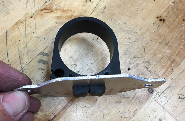 I also got a couple of BMW elbow tubes that connects to the ICV so they match the ports. The brass fitting are residential PEX tubing adaptor elbow 3/4 to 1/2. They happen to fit perfectly in the BMW hose and the 914 vacuum hose. shown in the picture is a small length of the 914 hose to validate. I intend to use hose clamps to avoid vacuum leaks. This setup will allow me to use the stock ports on the air filter and intake plenum. 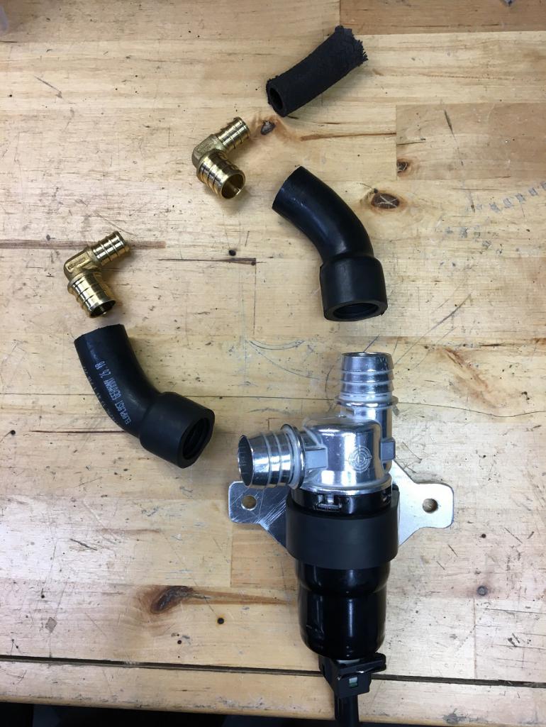 Last, the setup temporarily mounted on the cooling tin in the location where the coil usually goes. 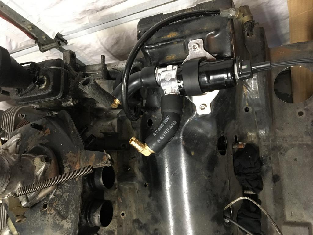 Next step; oil pump (IMG:style_emoticons/default/blink.gif) Yes, the"while in there" kicked in and I am revisiting my external oil cooler/thermostat/oil filter setup... (IMG:style_emoticons/default/smash.gif) |
|
|
|
| 913B |
Jan 13 2020, 12:58 AM
Post
#31
|
|
Senior Member Group: Members Posts: 881 Joined: 25-April 05 From: South Bay/SoCal Member No.: 3,983 Region Association: None |
BMW mount and rubber elbows tubes? from Where?
Sorry for all the inquiries. I purchased a Microsquirt as well and will be trying to modernize my 1.7 I hope (IMG:style_emoticons/default/beerchug.gif) Thank you Ted |
|
|
|
| Montreal914 |
Jan 13 2020, 08:33 AM
Post
#32
|
|
Advanced Member Group: Members Posts: 2,179 Joined: 8-August 10 From: Claremont, CA Member No.: 12,023 Region Association: Southern California |
Amazon and Ebay are usually my first go to places.
In this case, all of the following parts are from Amazon: 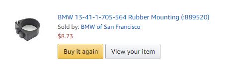 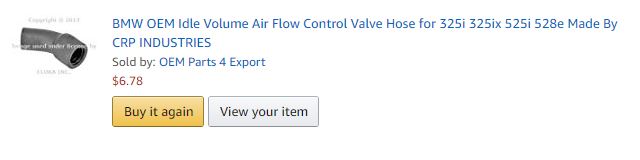 I was told or I read that a resistor like this needs to go on one of the negative wires of the ICV. I think it's the closing wire. To be looked into when connecting it... 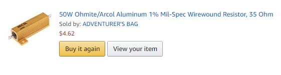 This tube adaptor will allow me to connect the GM MAP using a short length of 1/4 vacuum tube from a FLAP to the stock size vacuum hose for the stock MAP in the stock connection point in the plenum. 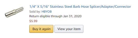 |
|
|
|
| Olympic 914 |
Jan 13 2020, 09:12 AM
Post
#33
|
|
Group: Members Posts: 1,789 Joined: 7-July 11 From: Pittsburgh PA Member No.: 13,287 Region Association: North East States |
Liking this, although I also struggle to understand the electronics of it. doesn't hurt to learn something new.
I'm guessing that with a system such as this, your cam choices would be expanded beyond the usual d-jet compatible cams. How much cam and head work would a system like this take? I understand you are wanting to use the d-jet pieces you have on hand. but could this work with the large bus plenum and throttle body? supposedly it has better flow characteristics than the 2.0 plenum. Just thinking out loud here... |
|
|
|
| GregAmy |
Jan 13 2020, 10:37 AM
Post
#34
|
|
Advanced Member Group: Members Posts: 2,686 Joined: 22-February 13 From: Middletown CT Member No.: 15,565 Region Association: North East States |
QUOTE(913B @ Jan 13 2020, 01:58 AM) I purchased a Microsquirt as well and will be trying to modernize my 1.7 I hope... (IMG:style_emoticons/default/beerchug.gif) That makes at least four in-process 914 Microsquirt retro-installs that I'm aware of...lots to be learned here. |
|
|
|
| sixnotfour |
Jan 13 2020, 11:40 AM
Post
#35
|
|
914 Wizard Group: Members Posts: 11,297 Joined: 12-September 04 Member No.: 2,744 Region Association: NineFourteenerVille |
QUOTE Busy weekend! Took the family to JPL's open doors yesterday to check out the Mars Rover before it leaves for Florida for the launch. (IMG:style_emoticons/default/beerchug.gif) Thats Awesome (IMG:style_emoticons/default/flag.gif) Great Microsquirt build up (IMG:style_emoticons/default/beer.gif) |
|
|
|
| Montreal914 |
Jan 13 2020, 10:43 PM
Post
#36
|
|
Advanced Member Group: Members Posts: 2,179 Joined: 8-August 10 From: Claremont, CA Member No.: 12,023 Region Association: Southern California |
QUOTE(Olympic 914 @ Jan 13 2020, 07:12 AM) Liking this, although I also struggle to understand the electronics of it. doesn't hurt to learn something new. My thought exactly, it's all about the learning experience with the hope that it will work (IMG:style_emoticons/default/laugh.gif) I'm guessing that with a system such as this, your cam choices would be expanded beyond the usual d-jet compatible cams. How much cam and head work would a system like this take? I'm no expert but your limitation is probably not the FI brain, more the components like the injectors at some point, all of the induction, etc... I understand you are wanting to use the d-jet pieces you have on hand. but could this work with the large bus plenum and throttle body? supposedly it has better flow characteristics than the 2.0 plenum. Just thinking out loud here... Yes the system has nothing to do with the plenum. There are many threads on Shoptalkforum about the use of the bus plenum, especially if you go with a larger engine like a stroker 2270. |
|
|
|
| 913B |
Jan 13 2020, 11:19 PM
Post
#37
|
|
Senior Member Group: Members Posts: 881 Joined: 25-April 05 From: South Bay/SoCal Member No.: 3,983 Region Association: None |
QUOTE(Montreal914 @ Jan 13 2020, 09:33 AM) Amazon and Ebay are usually my first go to places. In this case, all of the following parts are from Amazon: I was told or I read that a resistor like this needs to go on one of the negative wires of the ICV. I think it's the closing wire. To be looked into when connecting it... This tube adaptor will allow me to connect the GM MAP using a short length of 1/4 vacuum tube from a FLAP to the stock size vacuum hose for the stock MAP in the stock connection point in the plenum. Thank you It's appreciated. |
|
|
|
| Montreal914 |
Jan 19 2020, 08:27 PM
Post
#38
|
|
Advanced Member Group: Members Posts: 2,179 Joined: 8-August 10 From: Claremont, CA Member No.: 12,023 Region Association: Southern California |
A little more work done this weekend. (IMG:style_emoticons/default/smash.gif)
First, Friday ( I get every second Friday off (IMG:style_emoticons/default/pray.gif) ) I went to EMW and got my oil pump blocked off. They pressed a slug in the hole. It felt like it was protruding a little over the pump diameter so I gently filed it down and checked the diameter once done. It is now ready for the re-installation. I'm hoping to get a cast iron full flow pump cover with pressure relief from Gene Berg maybe tomorrow if they are open. 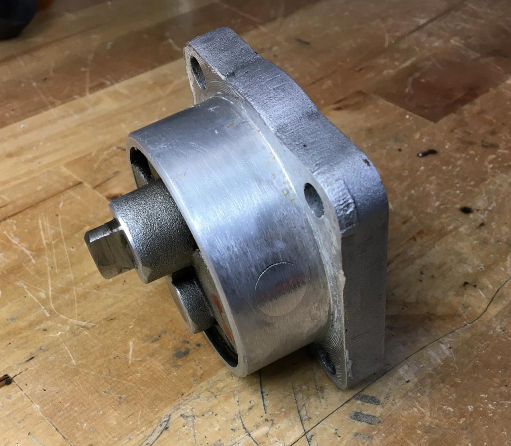 Then I fabricated a block off plate for the oil filter mount that I am removing. I used a 1/4" aluminum plate and my trusted hack saw, vise, file and HF drill... (IMG:style_emoticons/default/smash.gif) 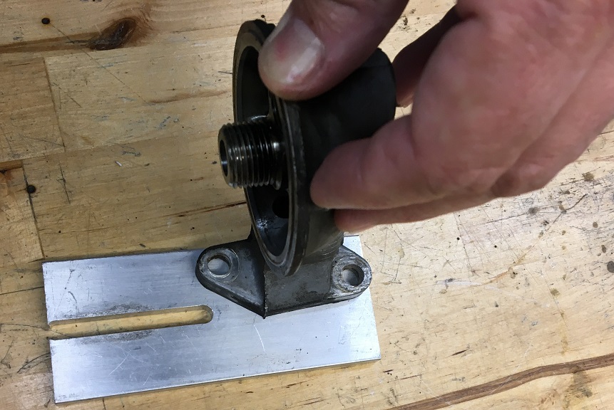 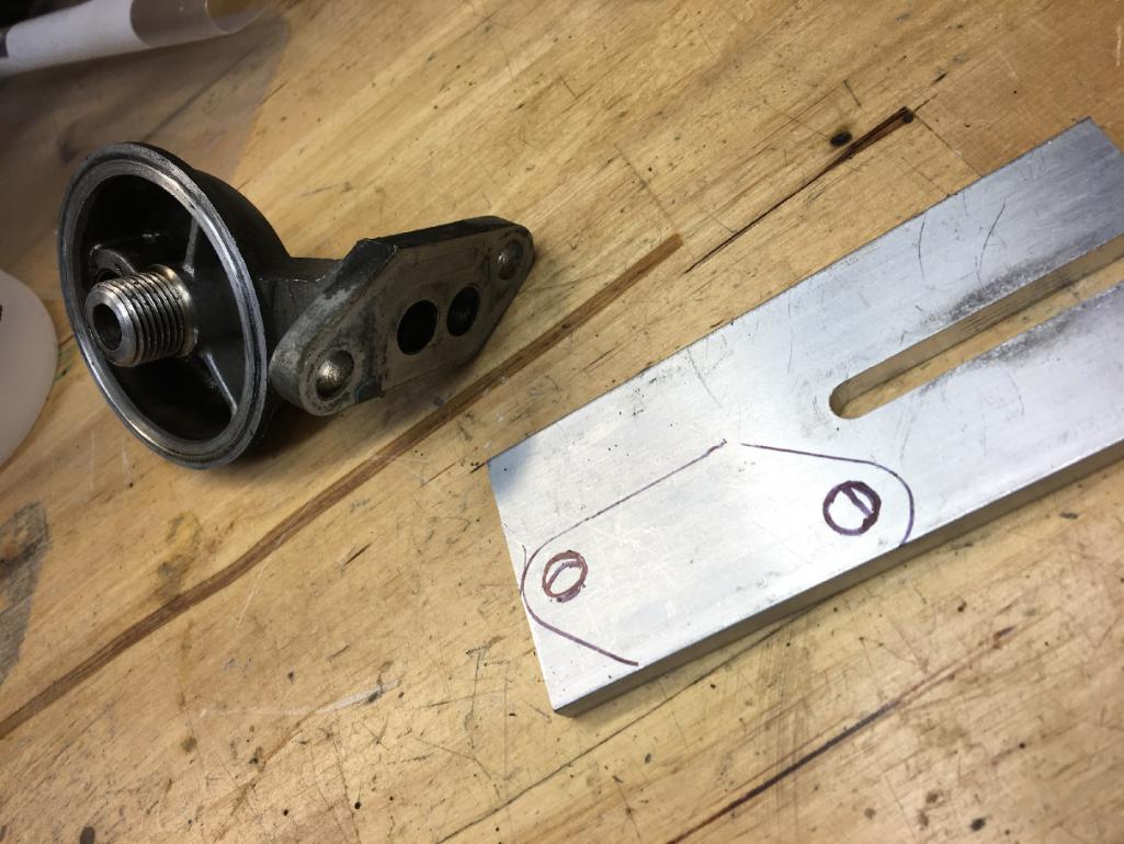 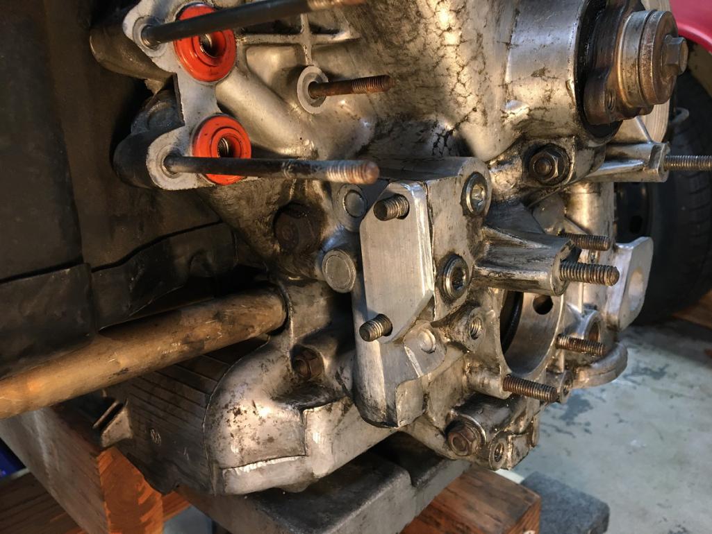 While I was at it making blanks, I also did one for the plenum as I will not be using the stock Cold Start Valve (CSV) anymore. 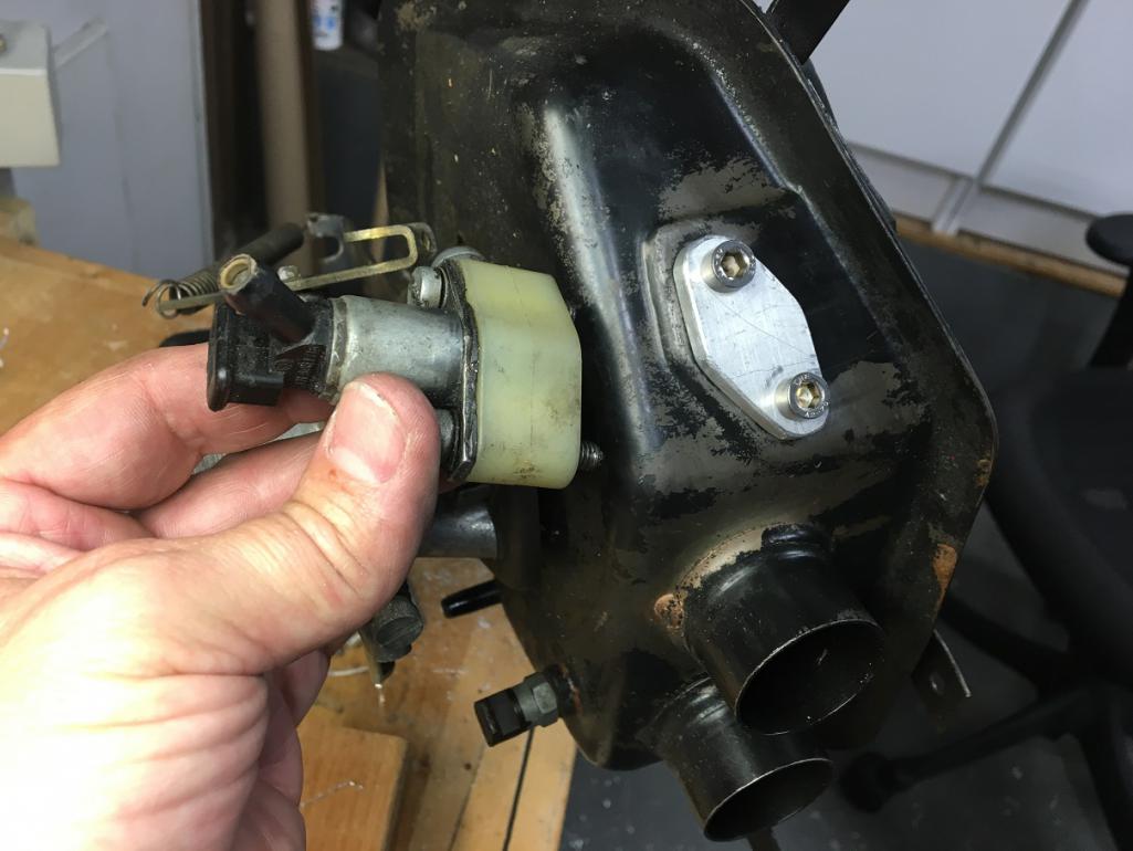 Next steps ahead, oil pump and cover installation, and Dub Shop crank trigger setup. (IMG:style_emoticons/default/smile.gif) (IMG:style_emoticons/default/beer3.gif) |
|
|
|
| JamesM |
Jan 21 2020, 09:44 AM
Post
#39
|
|
Advanced Member Group: Members Posts: 2,282 Joined: 6-April 06 From: Kearns, UT Member No.: 5,834 Region Association: Intermountain Region |
QUOTE(Montreal914 @ Jan 19 2020, 07:27 PM) While I was at it making blanks, I also did one for the plenum as I will not be using the stock Cold Start Valve (CSV) anymore. Not sure what your your plan is for the idle valve pluming, but that plastic block under the cold start injector is the port for the stock aux air regulator. May want to leave it and put your block off plate on top of it. |
|
|
|
| Montreal914 |
Jan 26 2020, 01:17 AM
Post
#40
|
|
Advanced Member Group: Members Posts: 2,179 Joined: 8-August 10 From: Claremont, CA Member No.: 12,023 Region Association: Southern California |
QUOTE(JamesM @ Jan 21 2020, 07:44 AM) QUOTE(Montreal914 @ Jan 19 2020, 07:27 PM) While I was at it making blanks, I also did one for the plenum as I will not be using the stock Cold Start Valve (CSV) anymore. Not sure what your your plan is for the idle valve pluming, but that plastic block under the cold start injector is the port for the stock aux air regulator. May want to leave it and put your block off plate on top of it. Thank you for pointing it out (IMG:style_emoticons/default/beerchug.gif) After reviewing the various ports on the plenum, the only one available for a 13mm ID hose is the plastic one by the stock CSV injector as you mentioned. Therefore, if I'm going with this hose setup on my BMW valve, I should use the plastic port and place the block off plate on top. I might revisit my plans to connect the BMW idle vale to the 10mm port that was used for the stock decel valve that will be removed. Otherwise I will need to plug that port. (IMG:style_emoticons/default/idea.gif) |
|
|
|
|
1 User(s) are reading this topic (1 Guests and 0 Anonymous Users)
0 Members:

|
Lo-Fi Version | Time is now: 1st August 2026 - 04:00 AM |
Invision Power Board
v9.1.4 © 2026 IPS, Inc.