|
|
|
Porsche, and the Porsche crest are registered trademarks of Dr. Ing. h.c. F. Porsche AG.
This site is not affiliated with Porsche in any way. Its only purpose is to provide an online forum for car enthusiasts. All other trademarks are property of their respective owners. |
|
|

  |

| Montreal914 |
 Jan 26 2020, 11:35 AM Jan 26 2020, 11:35 AM
Post
#41
|
|
Advanced Member  Group: Members Posts: 2,179 Joined: 8-August 10 From: Claremont, CA Member No.: 12,023 Region Association: Southern California |
Friday I received my 914 Rubber order (IMG:style_emoticons/default/mueba.gif) of various reassembly part needed for the project. The trailing group buy bushings are for later but I couldn't pass on these.
I will add the project related items to my spreadsheet which keeps on climbing (IMG:style_emoticons/default/dry.gif) . 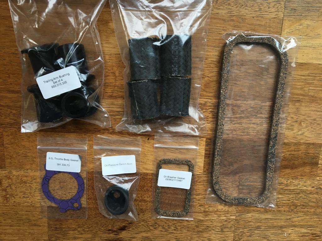 I spent some time in the garage yesterday and achieved a little more work on the project. Most of it was on the "while I am in there"... I removed the crankshaft seal and replaced it with a new one I had in my stock of parts. I also took the time to polish the impeller hub on the seal contact surface before reinstalling it, then torqued the bolt to 23 ft-lb as per spec. I used a steel plate I had laying around to prevent the hub from rotating while i was torquing. 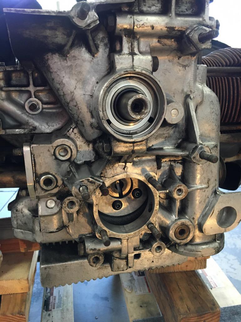 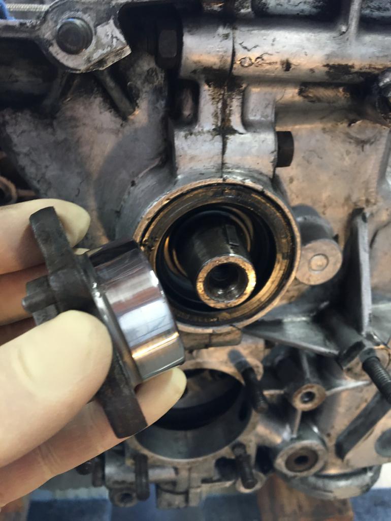 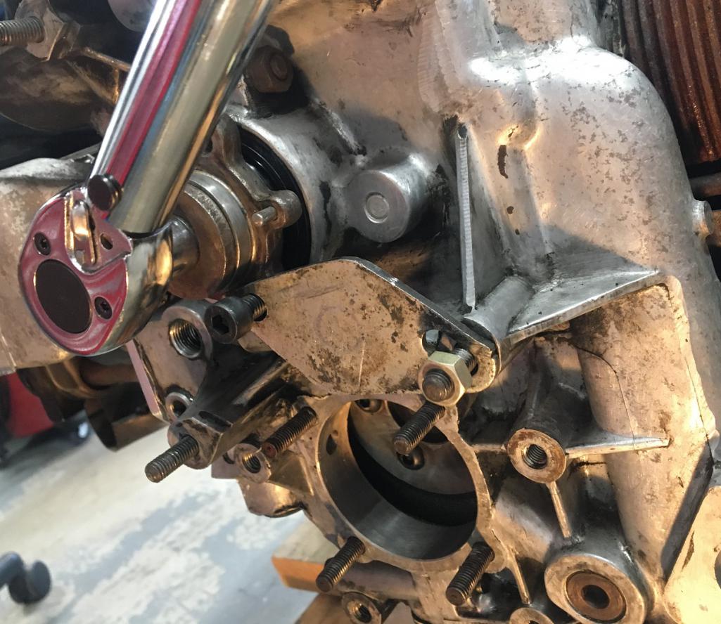 Before looking into the crank trigger installation, I revisited the sequence of assembly for all of the oil related components I needed to reinstall. First, the filter mount block off needs to go on. So I prepared a gasket for it and installed it. 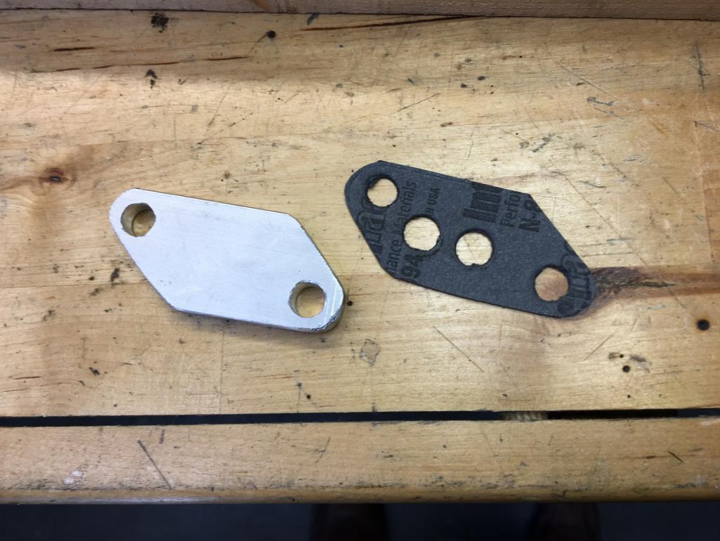 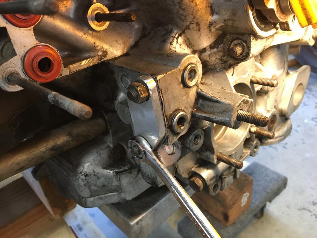 Then I removed the top oil galley plug since this is where my oil will feed the engine after going through the remote filter and cooler loop. Luckily, the 8mm Allen socket fits perfectly in the 3/8NPT plug as 5/16" and 8mm are very close. 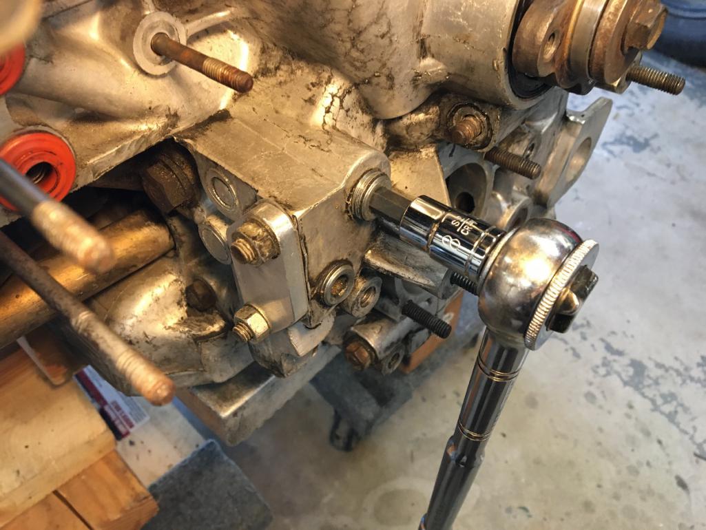 Then, I reinstalled the stock oil cooler in place. I have been debating about removing the cooler to allow more cooling to that cylinder bank as per Chris Foley's modification but I will keep that for when I rebuild my engine into a 2.3 stroker. Sorry no picture for that step but you get the idea... (IMG:style_emoticons/default/rolleyes.gif) Finally, I did a dry run of the crank trigger wheel installation to see how this fits. The Dub Shop parts fit very nicely, and as you can see will not interfere with any of my oil plumbing modifications. 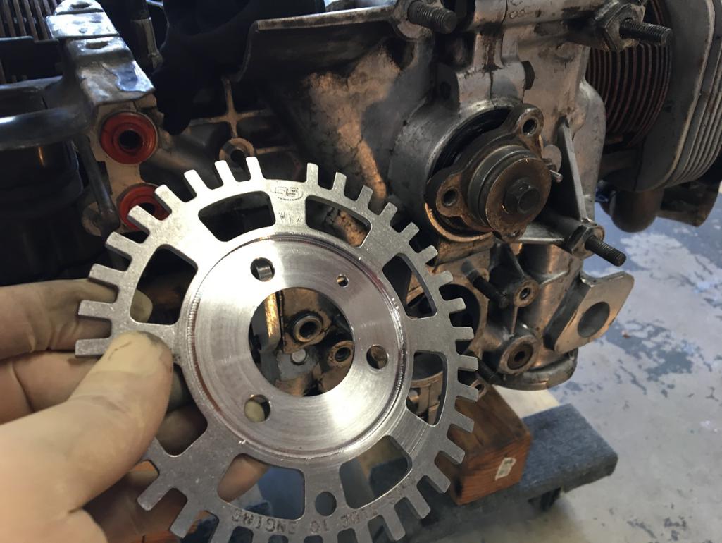 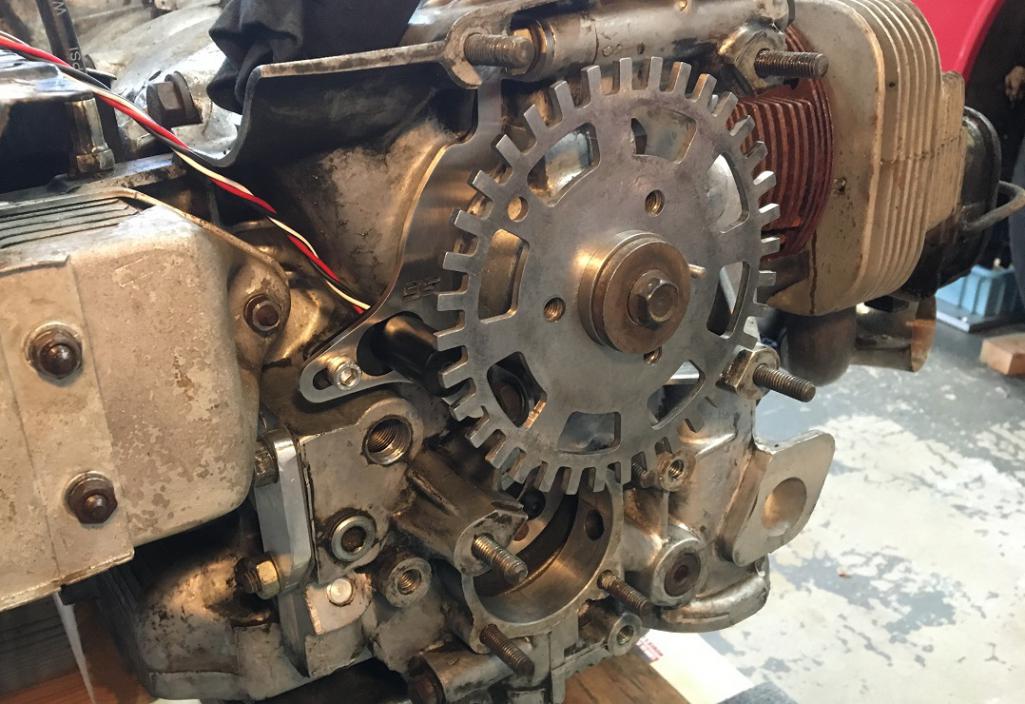 That's it for this weekend's work. Next steps ahead, finish the oil plumbing modifications and preparing the crank trigger final installation which will launch the reassembly of FI system. (IMG:style_emoticons/default/stirthepot.gif) |
   |

 
|
| Montreal914 |
Feb 29 2020, 11:51 AM
Post
#42
|
|
Advanced Member Group: Members Posts: 2,179 Joined: 8-August 10 From: Claremont, CA Member No.: 12,023 Region Association: Southern California |
A busy (non project related) month has passed already so it's time for me to post some of the updates on the work.
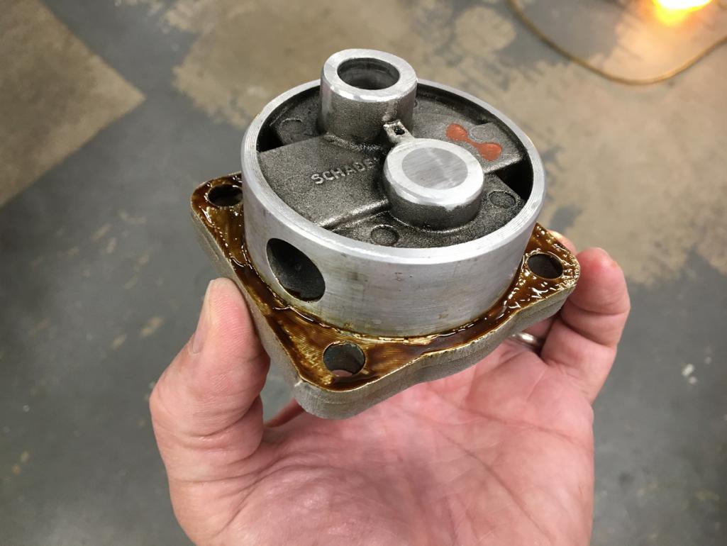
Although I have looked into ways of making the elbow feeding the oil back to the engine one that would have a nice sweep, I didn't come up with any good options. Anyway, I got what I believe to be a forged brass 3/8NPT elbow but the inner passage was not to my liking. The inner sharp corner that results from the machining of the ID from both side was so thin that is was already chipping. Clearly, it had to be massaged (IMG:style_emoticons/default/smash.gif) Before: 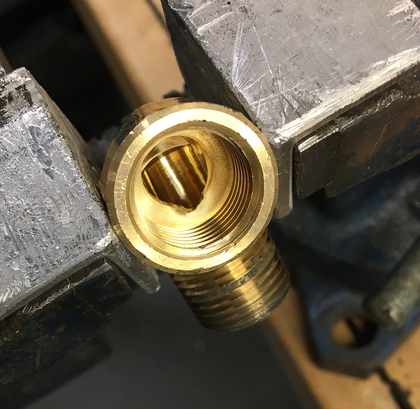 After: This should help to flow around this corner. Not only the passage was increased in size but the inner corner was rounded as much as I could with my various Dremel bits. 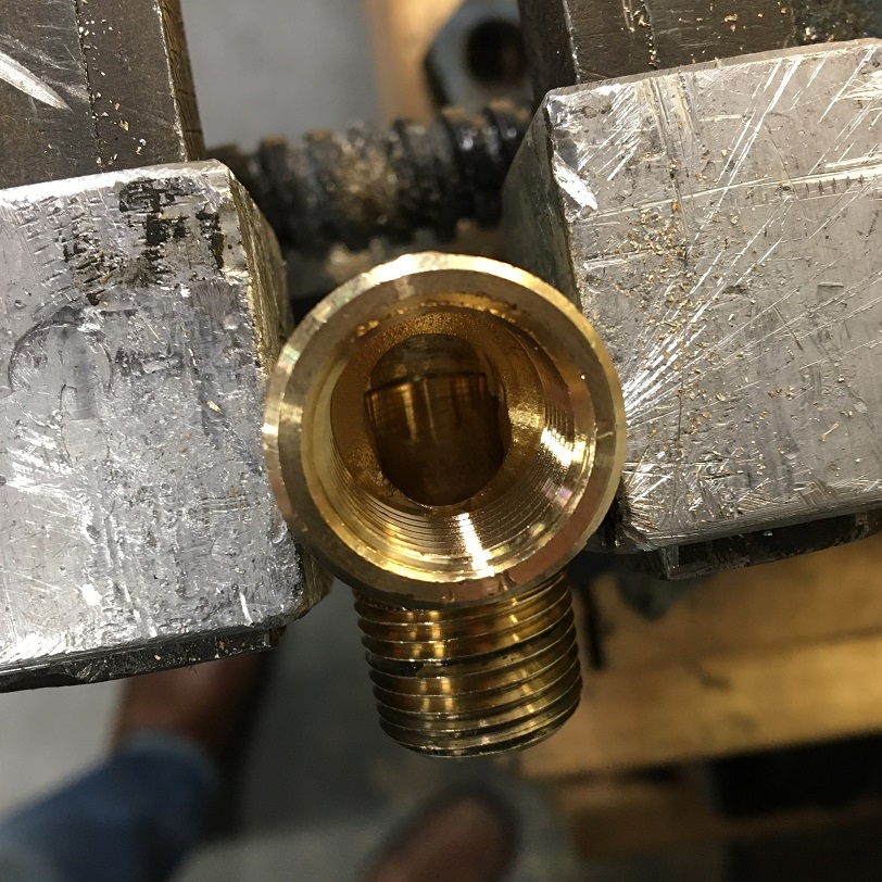 On to installation... The first dry run showed that there might be interference between the elbow and the engine block, so I did a little filing to ensure proper fit. 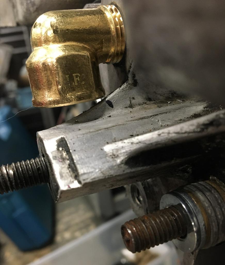 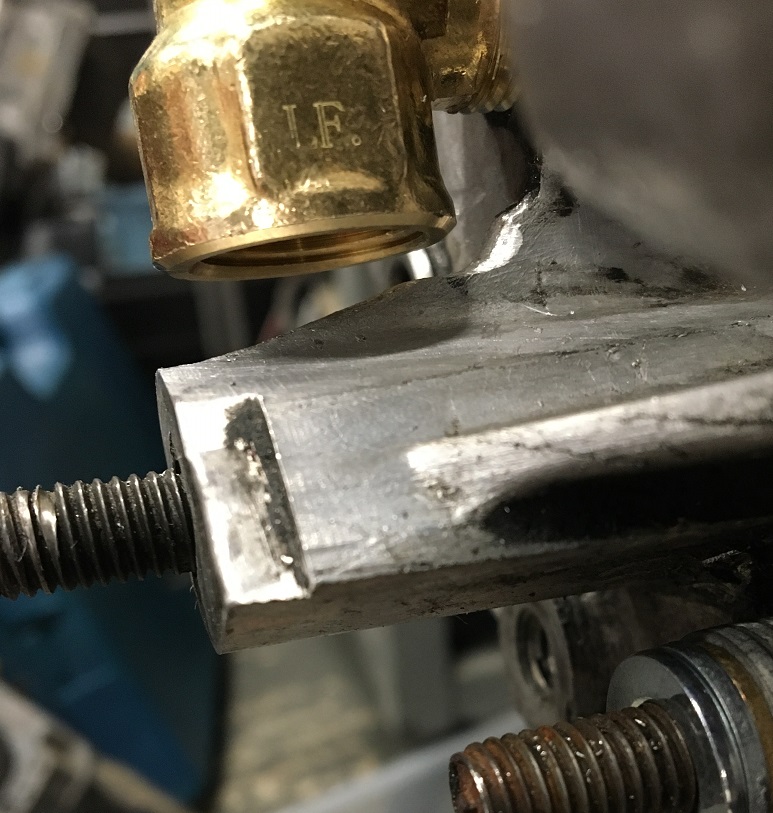 Final clocking: 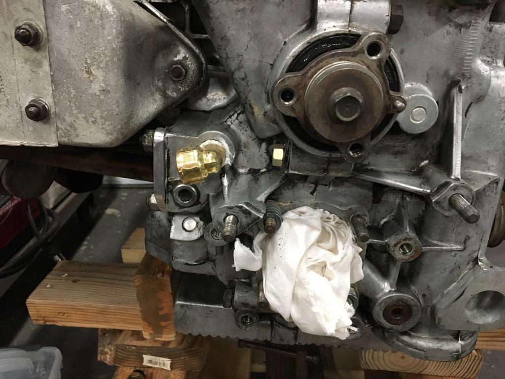 Moving on to the oil pump. My pump is a Type 1 Schadek 30mm, which is considered to be on the larger scale for the type 4 engine. That is why I went with @Mark Henry recommendation to use the Gene Berg pressure relief full flow cover. The issue with using a full flow cover is that the oil line (outlet) interfere's with the passenger side engine mount. There are different options to go around that. In my case, I decided that, for now, I would remove part of one of the two gussets, although this is not ideal. It is also a well know fact that elbows in fluid dynamics are pressure loss points. Ideally, one would use sweep elbow like the -AN tube style. After looking at the various pictures of existing setups documented here, I decided to go with a 45deg 3/8NPT male to 10AN male fitting on the pump cover. Then, my Parker Push-Lok 5/8" ID hose would terminate on a 45 degree sweep elbow 10AN female to mate to the cover fitting. This is helps reduce the pressure loss and minimize the modifications done to the engine mount. Enough talking... on with what people want! Pictures (IMG:style_emoticons/default/smile.gif) Gene Berg pressure relief full flow cover with AN 45deg elbow: 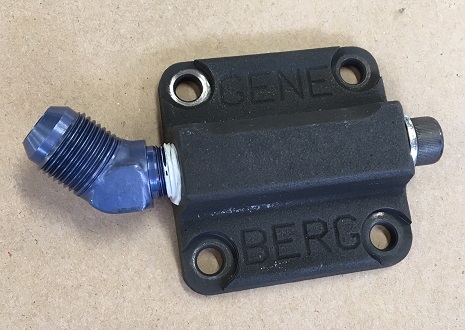 Clocking of the fitting for clearance issues: 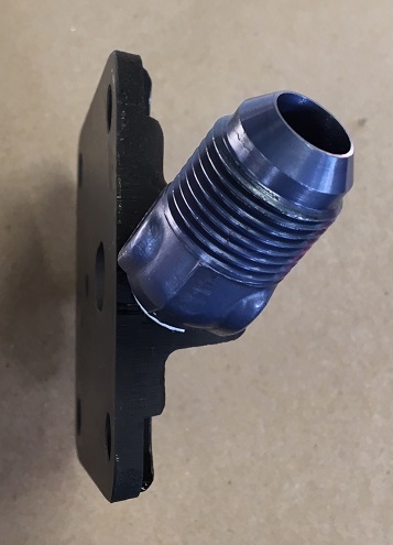 Backside view of the cover where we can see how its design feeds nicely into the outlet port. The other small hole is actually the pressure bypass that feeds back into the pump. Simple. 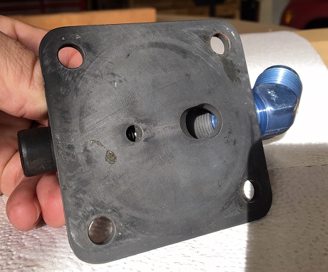 So now that we have this, what is the required clearance needed to the engine mount for all this to work. After a lot of back and forth and removing small portion at a time I came up with this shape to the mount. 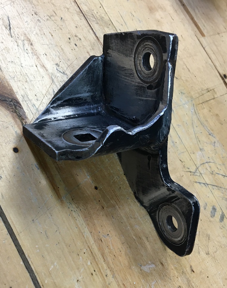 After sanding and rattle can paint: 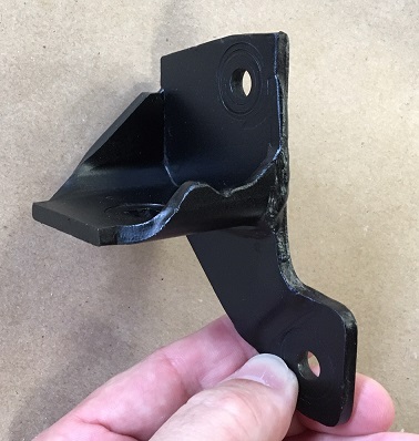 Coming up, engine mount and pump re-installation... |
|
|
|
| Montreal914 |
Feb 29 2020, 06:29 PM
Post
#43
|
|
Advanced Member Group: Members Posts: 2,179 Joined: 8-August 10 From: Claremont, CA Member No.: 12,023 Region Association: Southern California |
For the oil pump installation, I read here that Permatex sealant 80019 is recommended for this task. Paper gasket and gently pushed into place.
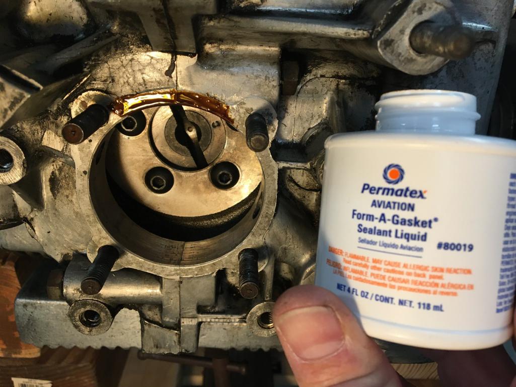 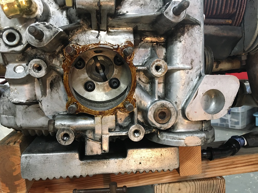 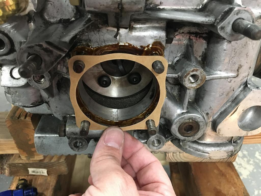   Since I want to do a final validation of the various clearances between the blue AN elbow on the pump cover, the engine mount, the mount upper bolt head, and the mating AN female fitting, I used the pump cover without any gasket or sealant and torqued down the nuts to set the pump itself. 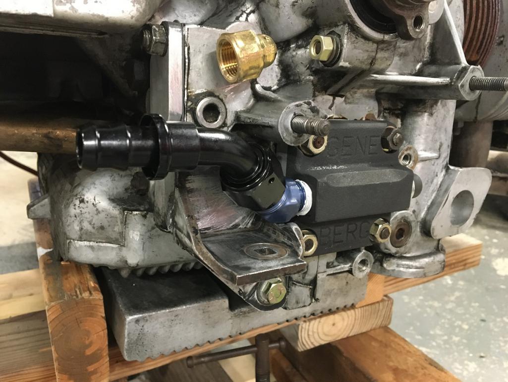 About a week later, I removed the nuts on the cover and began the clearance validation... There was a small interference between the blue elbow and the upper mount bolt so I filed away some of the fitting boss that is used for tightening it in place. Luckily not much was needed. First try, almost there: 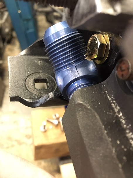 End result on the fitting (IMG:style_emoticons/default/dry.gif) 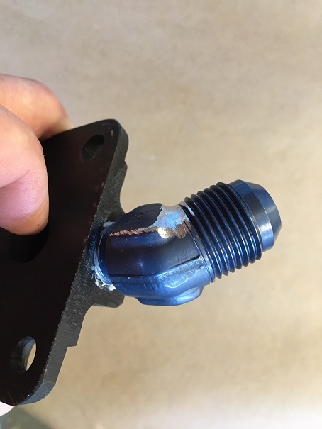 Here is the clearance between the blue elbow and the engine mount:   And here is everything including the rubber mount stud and mating female AN fitting. 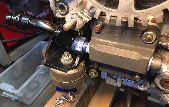 This setup will work but I am not 100% pleased with the outcome as it is a tight squeeze. There are better ways for achieving this. Mark Henry's engine mount modification and straight out fitting at the cover is more elegant. It requires more fabrication on the mount but it is much cleaner. McMark also has a version where he modifies the pump cover to have the outlet on the face instead of the side. With a 90 deg elbow screwed on the face of the cover, everything is cleared. This requires a cover with sufficient thickness to have enough thread engagement. |
|
|
|
| Montreal914 |
Feb 29 2020, 11:57 PM
Post
#44
|
|
Advanced Member Group: Members Posts: 2,179 Joined: 8-August 10 From: Claremont, CA Member No.: 12,023 Region Association: Southern California |
I finished preparing the Hall sensor by twisting the 3 wires and putting a heat shrink sleeve. I also slid over a rubber grommet that will go in the opening if the engine tin.
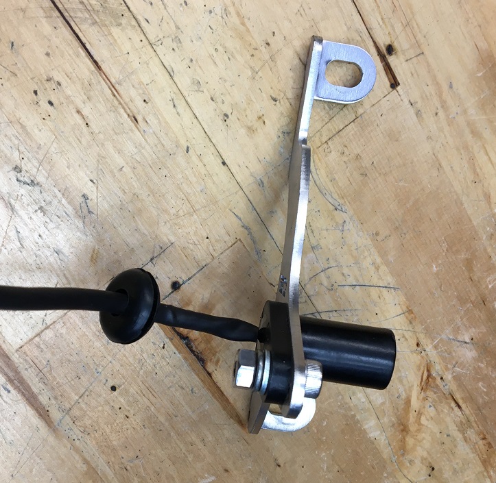 Installing the bracket for the Hall effect crank trigger I noticed the engine block has a small counter bore on the lower bolt of the crankshaft seal. I used a thin washer so that the bracket sits on a flat face, not a void. Before bracket installation: 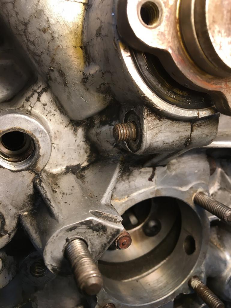 With crank sensor bracket on. We can't see it but there is a washer hidden between the block and the bracket (IMG:style_emoticons/default/biggrin.gif) 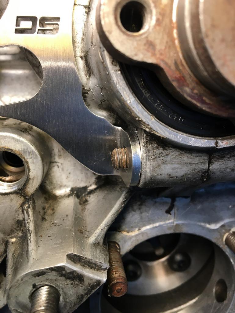 I adjusted the distance between the sensor face and the backside of the 36-1 toothed wheel to 2.1mm. Recommendation is less than 3mm. 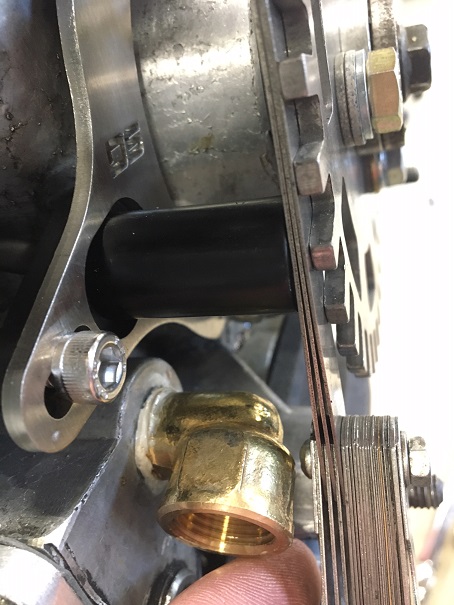 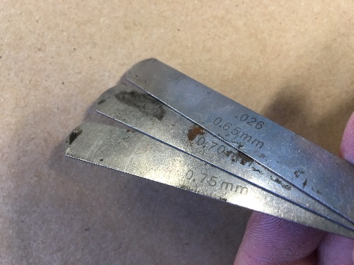 Last step for the day, I removed the distributor drive and installed the distributor plug. Here there are a few options available. I chose this one because of its design. The long center set screw actually pushes outward the bottom of the plug cut in 4 segments. This should prevent the plug from popping out. 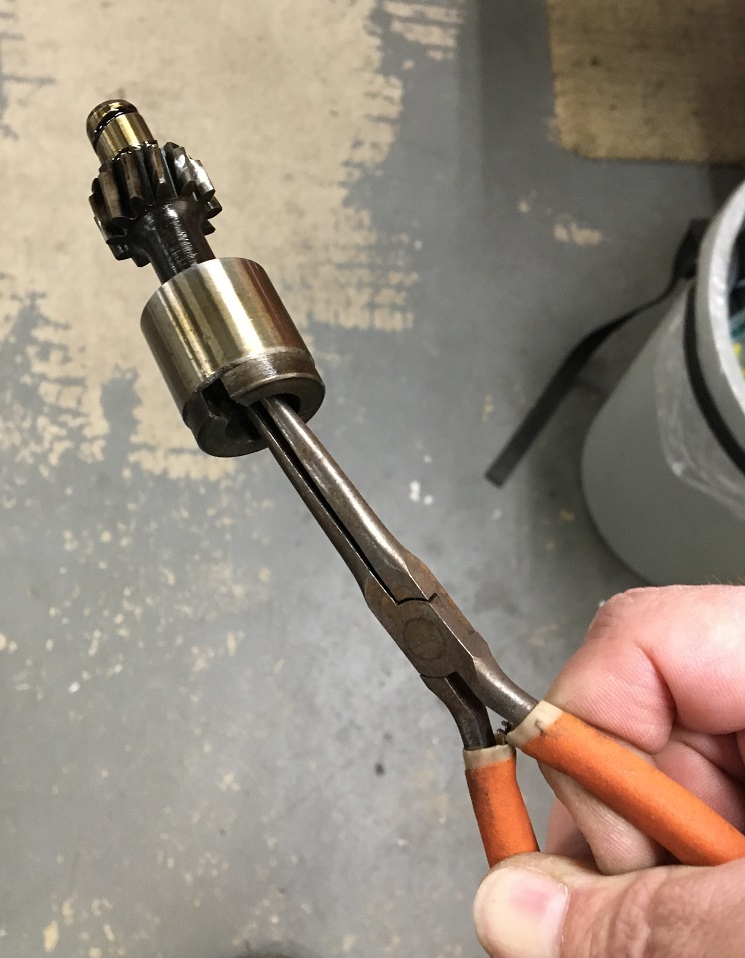 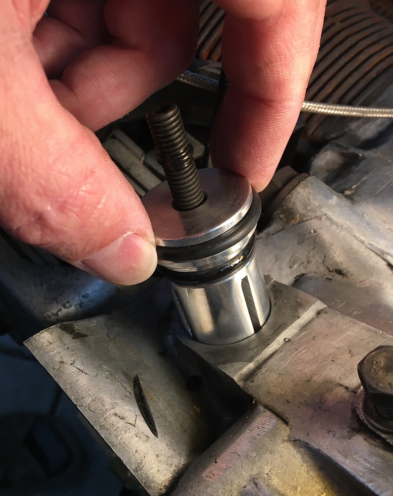 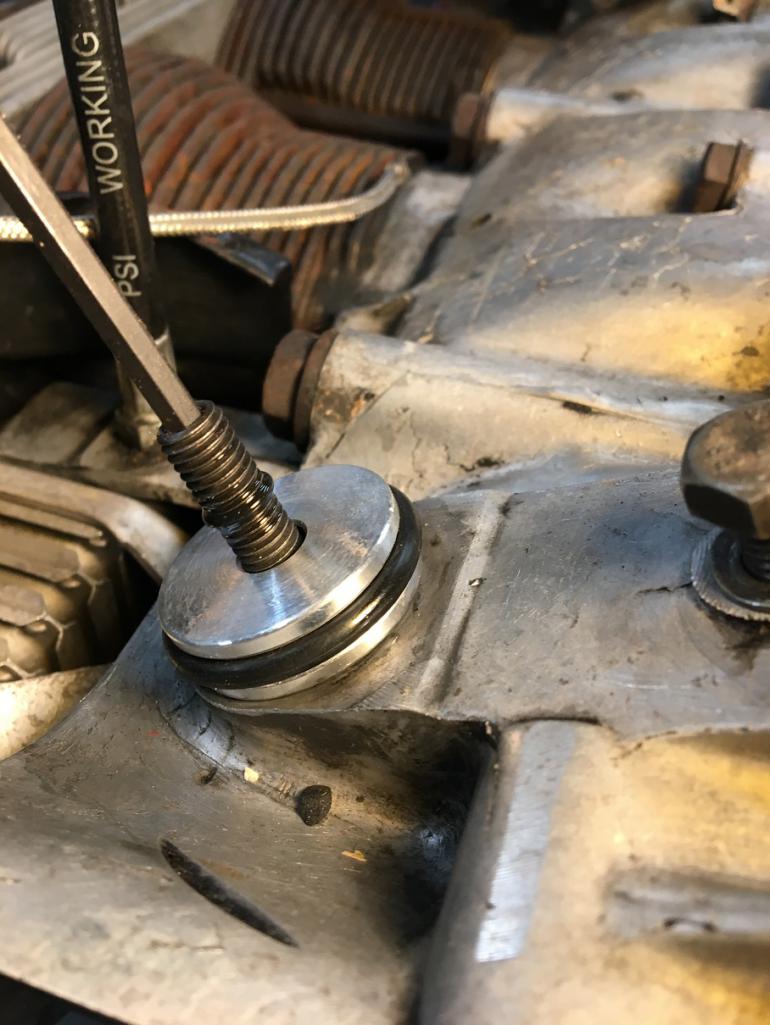 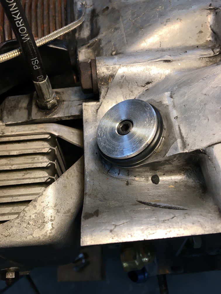 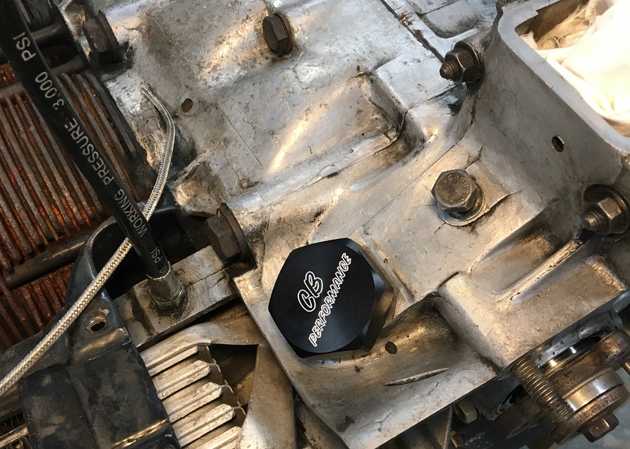 |
|
|
|
| Montreal914 |
Mar 28 2020, 02:07 PM
Post
#45
|
|
Advanced Member Group: Members Posts: 2,179 Joined: 8-August 10 From: Claremont, CA Member No.: 12,023 Region Association: Southern California |
Well it has been a month since my last post, time to give a little update on my project.
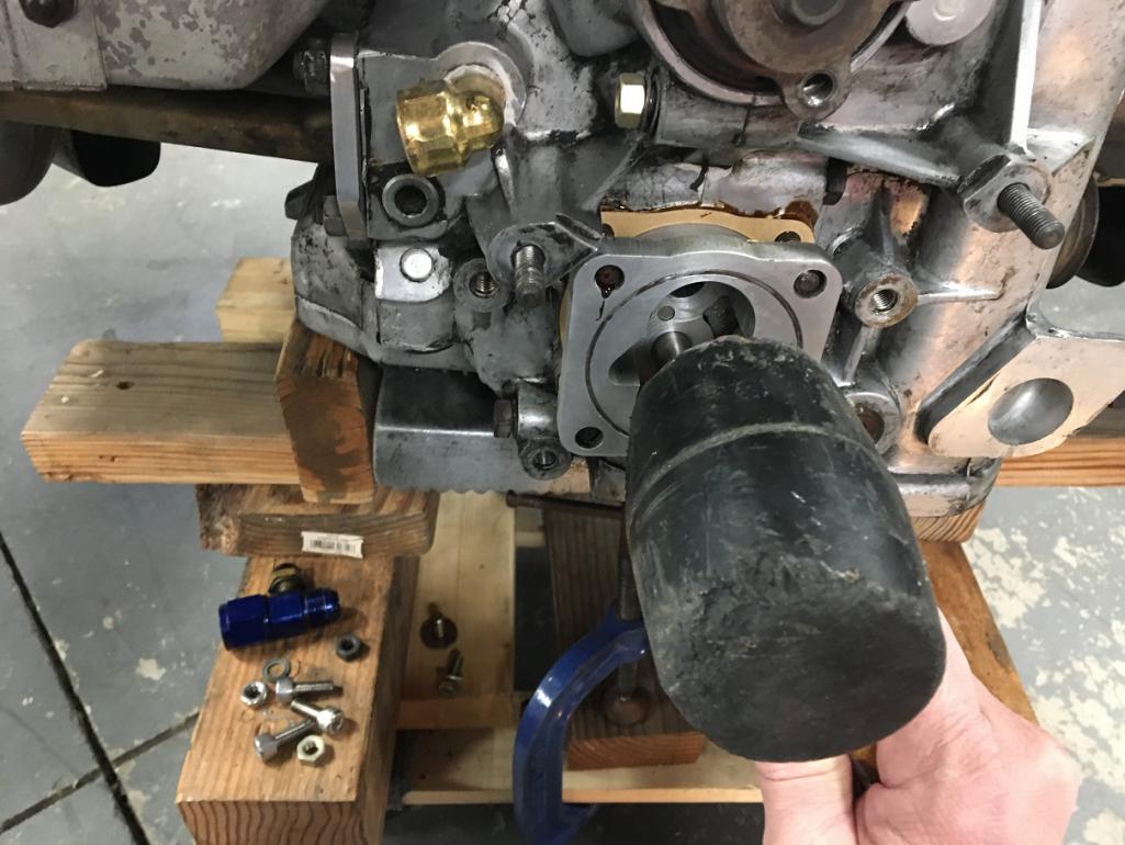
I should try to edit the title and add "Full Flow and also Fuel Pump Relocation" ... need to figure out how to do this though... (IMG:style_emoticons/default/idea.gif) Moving on to the driver side engine mount. The large socket head cap screw sticking out of the Gene Berg oil pump cover is holding the pressure relief spring. This head comes in conflict with the engine mount. So this side too need to be modified... (IMG:style_emoticons/default/dry.gif) 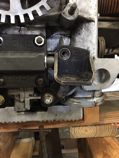 After modification and paint: 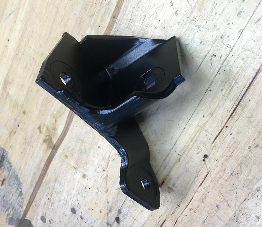 Mount installed and oil pump reassembly process. Assembly lube on the gears and ready to close it up: 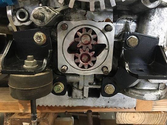 Gooped paper thin gasket: 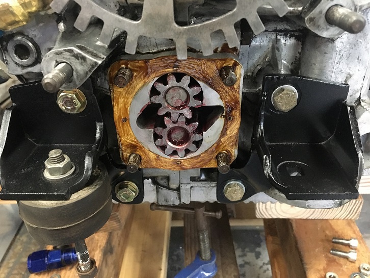 Final pump assembly with the two modified engine mounts, nice milestone (IMG:style_emoticons/default/beer3.gif) 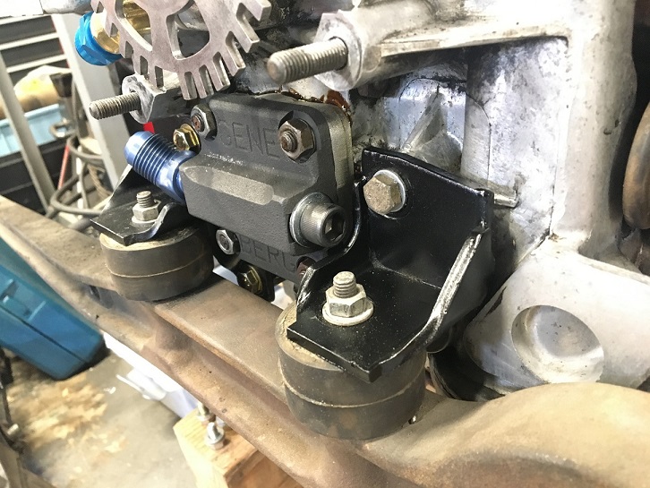 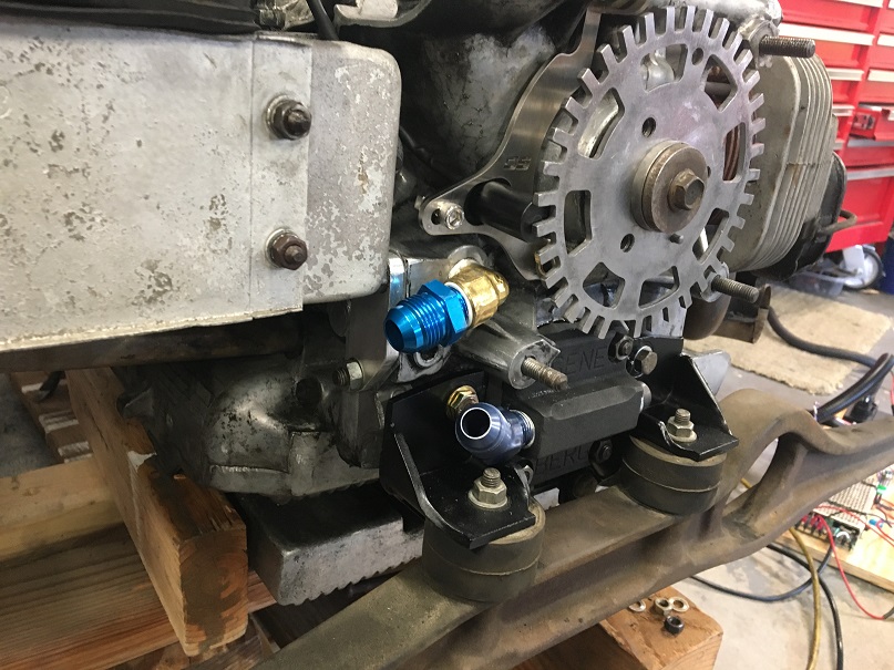 |
|
|
|
| Montreal914 |
Mar 28 2020, 03:21 PM
Post
#46
|
|
Advanced Member Group: Members Posts: 2,179 Joined: 8-August 10 From: Claremont, CA Member No.: 12,023 Region Association: Southern California |
Next step, prepare the oil lines that need to be installed before the fan housing goes back on. To prepare the lines I needed to establish their length.
The lines will be connected to the remote filter - H type oil thermostat panel. First, using aluminum parts I had, and my trusted hack saw, HF drill and file, I prepared this integrated setup that will be mounted on the passenger side lower firewall. You can see the remote oil filter mount and H-type oil thermostat. The 2 blue AN-10 fittings on the right are for the lines coming from and going to the engine. Note that this oil filter mount can be used in various configurations. In this case, you can see that one port is plugged on each side (silver plug). Arrows allow to see the flow path. 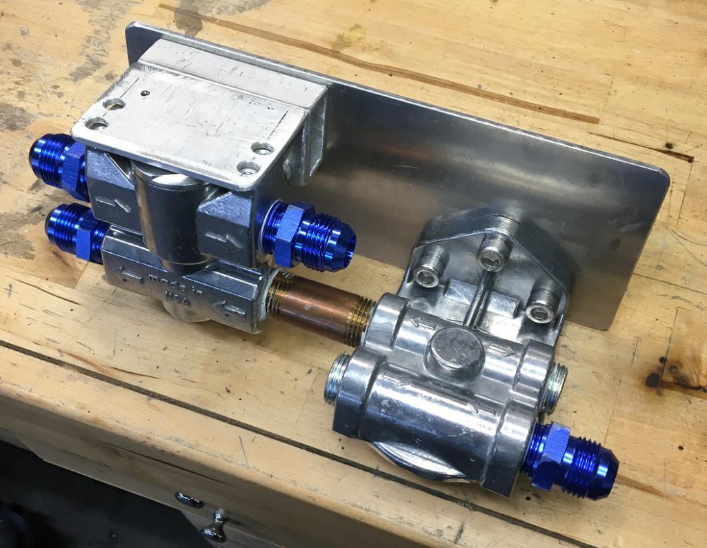 Oil flow; Oil is siphoned from the engine case by the oil pump. Pump pushes the oil out of the engine via the pump cover, and feeds the remote oil filter. From the filter, oil goes to the thermostat. If the oil is below 180F, the thermostat is closed and the oil goes back to the engine (thermostat upper right port). At about 180F, the thermostat opens and the oil is routed to the external oil cooler via the thermostat lower left port and loops back to the thermostat upper left port then through it and back to the engine. Moving on... (IMG:style_emoticons/default/biggrin.gif) After taking a few reference measurement I did a quick mock-up of the setup to define the actual length of the oil lines linking the engine to the filter/thermostat panel, 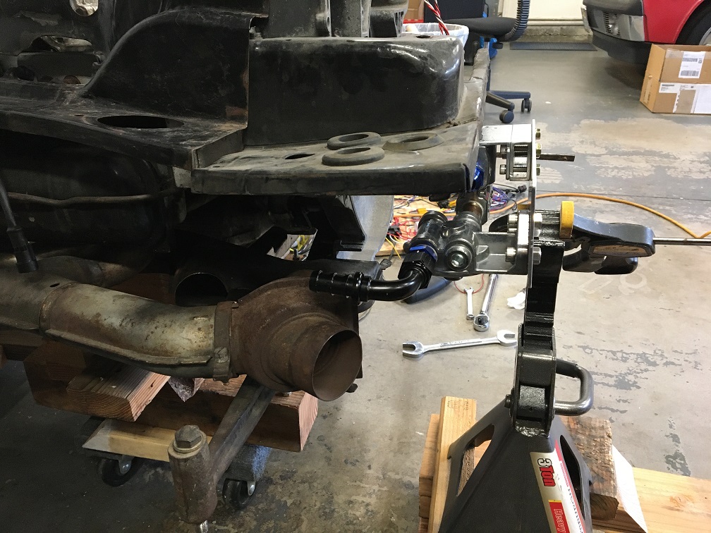 Whit this in place, I was able to prepare the oil lines. I am using Parker Push-Lok high temperature 836-10 blue hose. The 10 is for 5/8" (as in 10/16") and will be a perfect fit for my aluminum AN-10 push-on fittings. 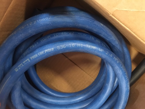 And Voilà! just like that a couple of lines installed! We are now ready to move on to the reassembly of the engine tin, fan housing and fan. (IMG:style_emoticons/default/beer.gif) 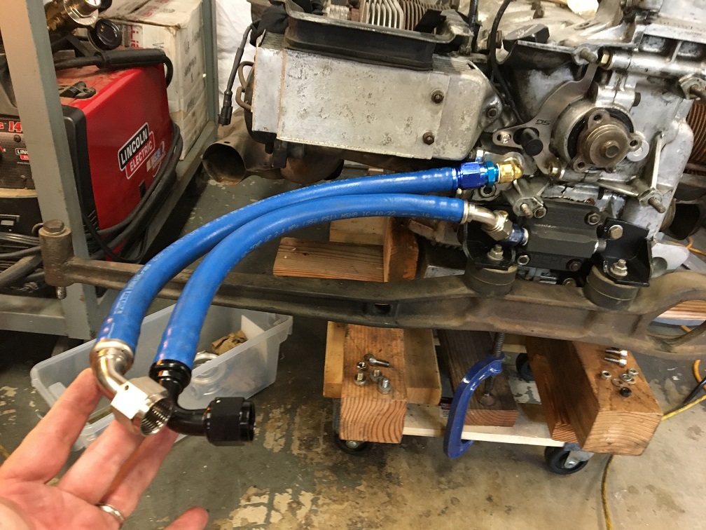 |
|
|
|
| GregAmy |
Mar 29 2020, 07:55 AM
Post
#47
|
|
Advanced Member Group: Members Posts: 2,686 Joined: 22-February 13 From: Middletown CT Member No.: 15,565 Region Association: North East States |
(IMG:style_emoticons/default/drunk.gif)
Eric, maybe I missed it above, but are you leaving the stock cooler in place? On my race car (uses a CB Performance dry sump pump), Chris Foley built a block that replaces the cooler and routes the oil straight back in, allow me to remove the cooler, factory flaps/controls, and put a piece of sheet metal where the cooler was to flow more air to that side. Leaving it in is fine but I like the concept of removing the factory cooling flaps and one more item that could fail (the cooler, though it's rare for it to fail). |
|
|
|
| Montreal914 |
Mar 29 2020, 12:56 PM
Post
#48
|
|
Advanced Member Group: Members Posts: 2,179 Joined: 8-August 10 From: Claremont, CA Member No.: 12,023 Region Association: Southern California |
QUOTE(GregAmy @ Mar 29 2020, 06:55 AM)  (IMG:style_emoticons/default/drunk.gif) Eric, maybe I missed it above, but are you leaving the stock cooler in place? On my race car (uses a CB Performance dry sump pump), Chris Foley built a block that replaces the cooler and routes the oil straight back in, allow me to remove the cooler, factory flaps/controls, and put a piece of sheet metal where the cooler was to flow more air to that side. Leaving it in is fine but I like the concept of removing the factory cooling flaps and one more item that could fail (the cooler, though it's rare for it to fail). Greg, for this time around, I am keeping the stock cooler in. My hope for the next evolution is to stroke it to 2256cc and then, I will remove it à la Chris Foley to increase cooling to #3. I might also revisit the plumbing at that point. The way I did it look OK but there is no access to the oil lines connections at the engine whereas with Chris', it should be possible to play in that area. The remote filter thermostat panel will be set on the passenger side lower firewall, the connections to the external oil cooler are aiming towards the driver side and would be ready for a front mounted oil cooler with lines running along the driver side. Again, for the next round. For now, I will route the lines to the back cooler but from the driver side of the gearbox. No plan set on that yet. |
|
|
|
| Montreal914 |
Apr 24 2020, 08:25 PM
Post
#49
|
|
Advanced Member Group: Members Posts: 2,179 Joined: 8-August 10 From: Claremont, CA Member No.: 12,023 Region Association: Southern California |
I did some good progress recently with all of this time staying home.
Before installing the engine tin back on, I made a small modification to the cylinder 3-4 tin to fit the crank trigger sensor wire grommet. Here you can see the U shaped opening that I will create. As a reference, the large round hole is for the oil pressure sensor grommet. 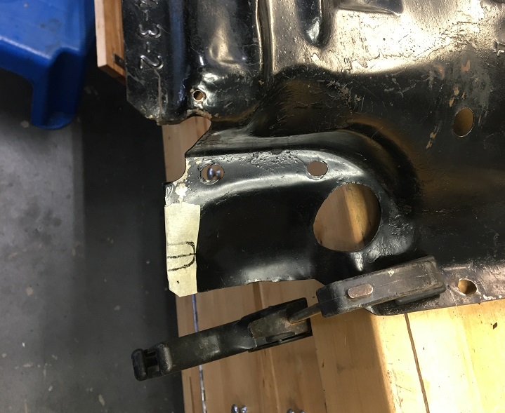 And the test fit of the grommet. 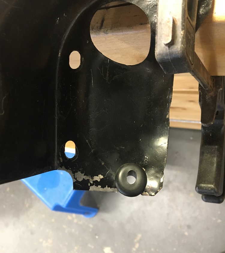 Then I installed all of the engine tin back on and replaced the belt too. 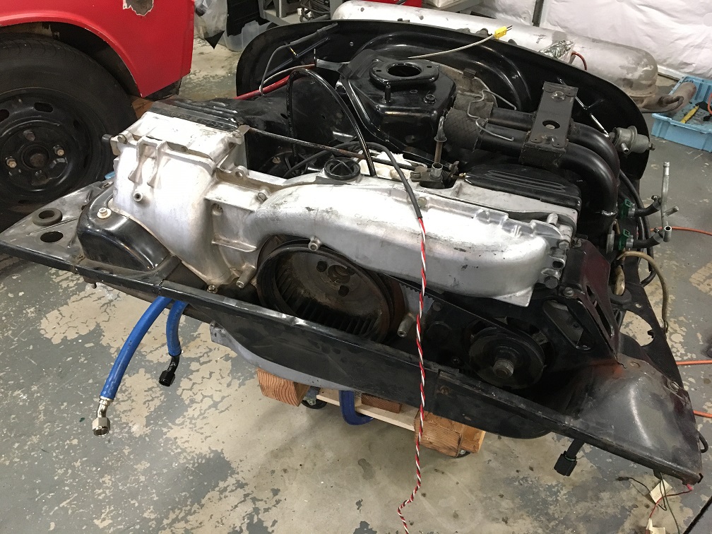 Here you can see the distributor plug, the the oil pressure boot (914 Rubber) and my HF grease gun high pressure hose for remote oil pressure sender. Also, you can see the crank trigger wire safely installed. 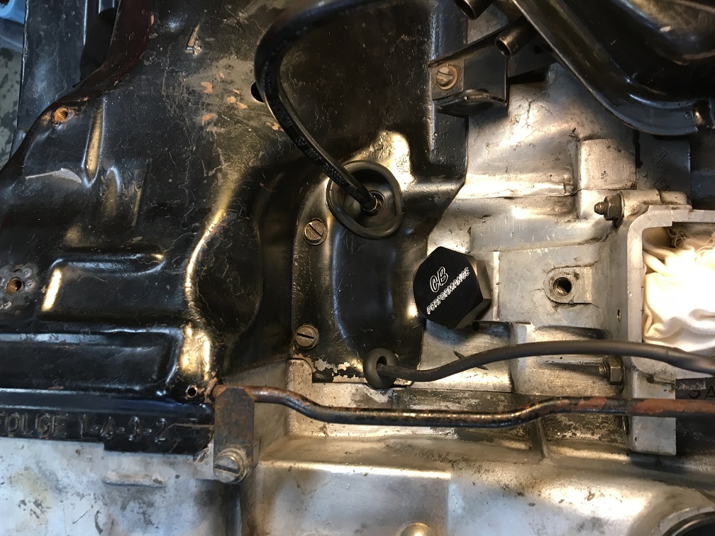 Many new things in this next picture. First, the coil mount fabricated earlier in the thread got painted and installed using the distributor clamp M8 thread in the engine block and the cylinder 3-4 tin 2 mounting screws. The bracket was designed to support the modern VW coil the way it is meant to be, resting on the three mounting points, not on its base. It also supports the MAP sensor seen below the coil. You can also see the rubber vacuum line connected to the MAP sensor. This 6mm hose connects to the standard 914 8mm hose with an aluminum step up barb fitting. You can see the other end of the MAP hose where it has become the standard 8mm hose and connects to the stock location on the plenum. 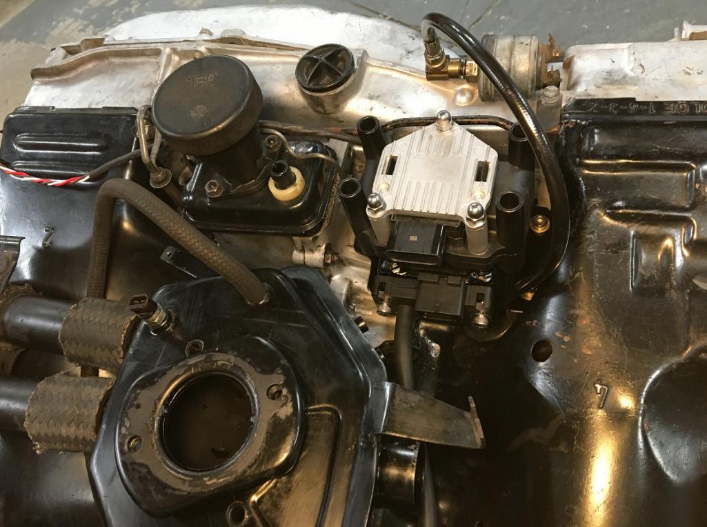 Aluminum step up barb fitting and hose transition. 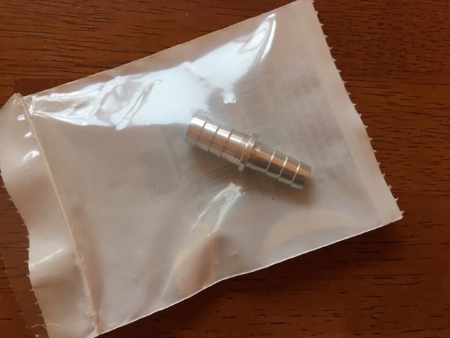 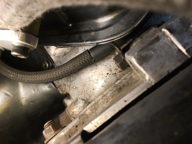 Intake runners and stock green injectors reinstalled with fresh o-rings. 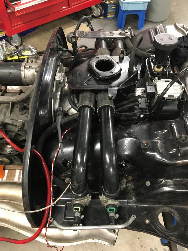 Next, I upgraded my Magnecore 8.5mm ignition wires so they could be used with the new VW coil. I ordered LS style terminals and the crimping tool. These next pictures show the various steps involved in this modification. Hopefully, they will work properly... First, I pulled of the distributor end boot. 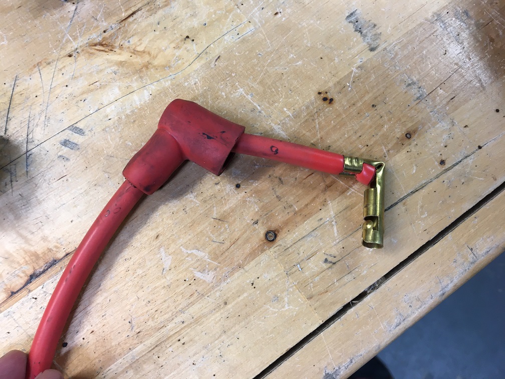 Then removed the crimped terminal... 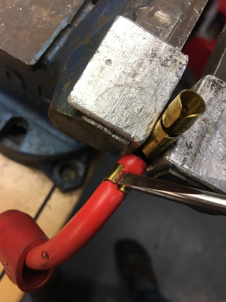 And here we have the wire ready to receive its new terminal. 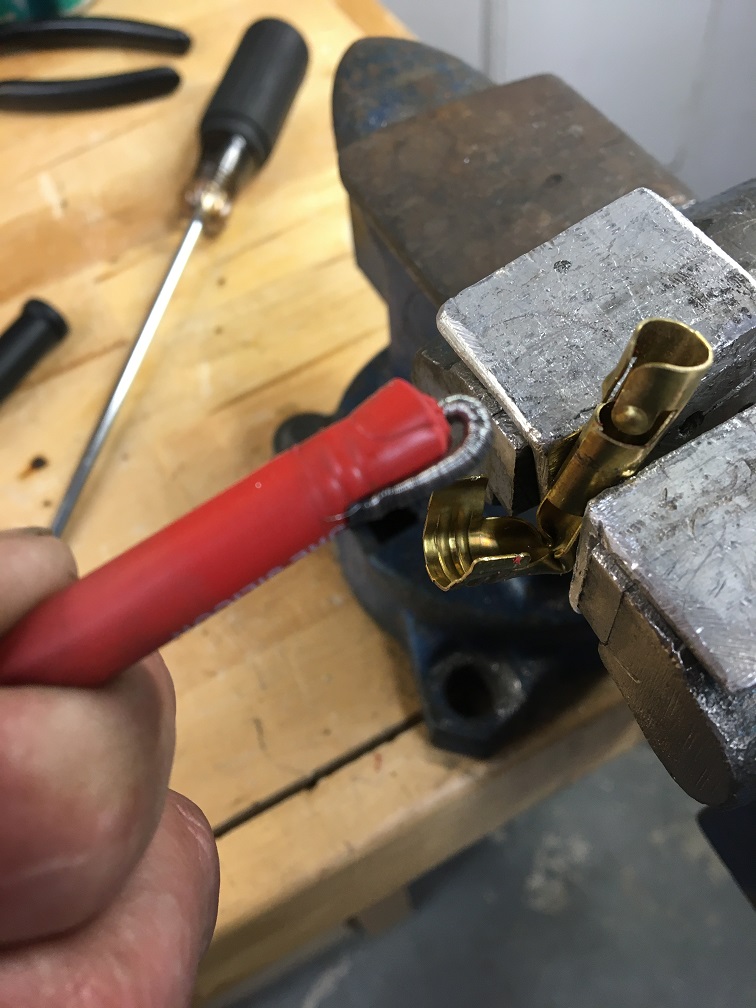 Using the MSD crimping tool, the new terminal can be crimped on with a wise. Don't forget to slide on the boot first though. 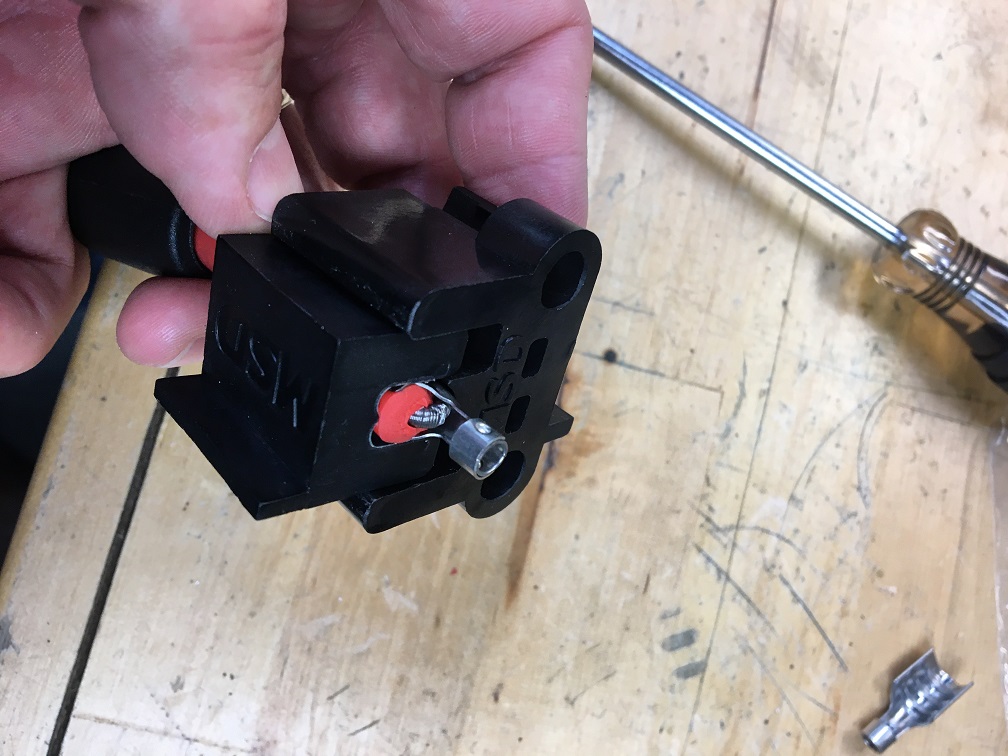 Here is the finished result. 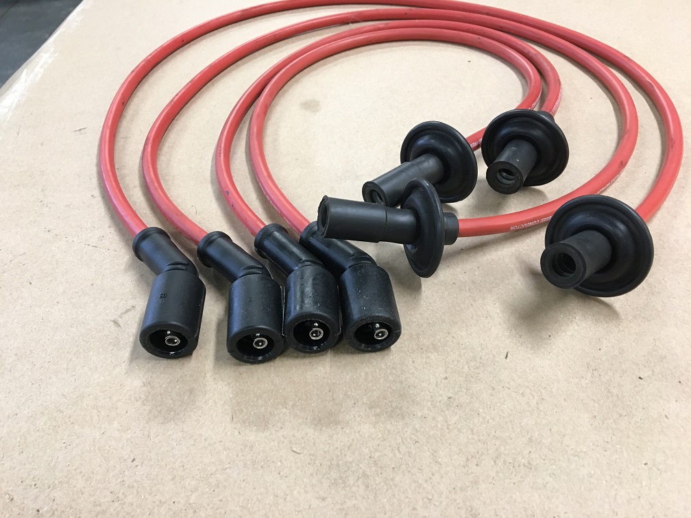 With these ready, they can be installed on the engine. 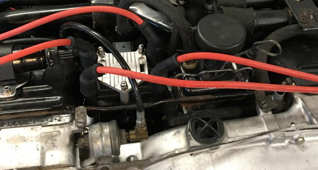 |
|
|
|
| GregAmy |
Apr 25 2020, 09:27 AM
Post
#50
|
|
Advanced Member Group: Members Posts: 2,686 Joined: 22-February 13 From: Middletown CT Member No.: 15,565 Region Association: North East States |
|
|
|
|
| PlaysWithCars |
Apr 25 2020, 11:07 PM
Post
#51
|
|
Senior Member Group: Members Posts: 544 Joined: 9-November 03 From: Southeast of Seattle Member No.: 1,323 Region Association: Pacific Northwest |
Digging the MSD crimping tool and results. I hadn't seen that before. Pretty slick.
|
|
|
|
| bohalrantipol |
Apr 19 2021, 10:37 AM
Post
#52
|
|
Member Group: Members Posts: 53 Joined: 11-December 06 From: VA Member No.: 7,353 Region Association: MidAtlantic Region |
Good write up! I am hoping there is an update.
|
|
|
|
| Mark Henry |
Apr 19 2021, 10:51 AM
Post
#53
|
|
that's what I do! Group: Members Posts: 20,065 Joined: 27-December 02 From: Port Hope, Ontario Member No.: 26 Region Association: Canada |
Good work! (IMG:style_emoticons/default/smile.gif)
Some peeps question (get mad) why my billed labour gets so high for custom work...this is why, custom work is a beyond major time suck. |
|
|
|
| ClayPerrine |
Apr 19 2021, 02:38 PM
Post
#54
|
|
Life's been good to me so far..... Group: Admin Posts: 16,567 Joined: 11-September 03 From: Hurst, TX. Member No.: 1,143 Region Association: NineFourteenerVille |
This is some beautiful work.
If I might make a suggestion..... Use the injectors from a 1980 Datsun/Nissan 280ZX. The impedance on them matches the modern FI better than the D-Jet injectors, and the are sized right for a 2.0L motor. And they are way easier to find than a D-Jet injector. Sell the D-Jet injectors to someone running stock D-Jet. Clay |
|
|
|
| Mark Henry |
Apr 20 2021, 07:43 AM
Post
#55
|
|
that's what I do! Group: Members Posts: 20,065 Joined: 27-December 02 From: Port Hope, Ontario Member No.: 26 Region Association: Canada |
He already has it set up as low impedance, I wouldn't change that. I've run an 1.8, 2.0 and a 2.0 with a SCAT C-25 cam on 2.0 Djet injectors with great success.
Hi or low impedance injectors I don't think there's any consensus of one being better than the other, just with high impedance you don't have to use a resistor pack and they are more common now. Speaking of the resistor pack, make sure it's isolated as it can get hot with long periods of WOT. Not a big deal, you just don't want things like wire and plastic laying on it. |
|
|
|
| bohalrantipol |
Apr 20 2021, 08:30 AM
Post
#56
|
|
Member Group: Members Posts: 53 Joined: 11-December 06 From: VA Member No.: 7,353 Region Association: MidAtlantic Region |
I am going to post this here as it is pretty thorough microsquirt build.
https://tgadrivel.blogspot.com/2020/03/on-m...914-part-1.html If you dont want it here @GregAmy I will delete it |
|
|
|
| ClayPerrine |
Apr 20 2021, 08:33 AM
Post
#57
|
|
Life's been good to me so far..... Group: Admin Posts: 16,567 Joined: 11-September 03 From: Hurst, TX. Member No.: 1,143 Region Association: NineFourteenerVille |
QUOTE(Mark Henry @ Apr 20 2021, 08:43 AM) He already has it set up as low impedance, I wouldn't change that. I've run an 1.8, 2.0 and a 2.0 with a SCAT C-25 cam on 2.0 Djet injectors with great success. Hi or low impedance injectors I don't think there's any consensus of one being better than the other, just with high impedance you don't have to use a resistor pack and they are more common now. Speaking of the resistor pack, make sure it's isolated as it can get hot with long periods of WOT. Not a big deal, you just don't want things like wire and plastic laying on it. I was just thinking of injector availability and the value of D-Jet injectors. Clay |
|
|
|
| GregAmy |
Apr 20 2021, 11:44 AM
Post
#58
|
|
Advanced Member Group: Members Posts: 2,686 Joined: 22-February 13 From: Middletown CT Member No.: 15,565 Region Association: North East States |
QUOTE(bohalrantipol @ Apr 20 2021, 09:30 AM) If you dont want it here...I will delete it No worries! I hope it can be helpful. Eric ( @Montreal914 ) and I have conversed a lot of both projects (and you'll notice in the blog I credited him for several ideas)…we all need to send him some motivation to finish his project! |
|
|
|
| Mark Henry |
Apr 20 2021, 11:46 AM
Post
#59
|
|
that's what I do! Group: Members Posts: 20,065 Joined: 27-December 02 From: Port Hope, Ontario Member No.: 26 Region Association: Canada |
QUOTE(ClayPerrine @ Apr 20 2021, 10:33 AM) QUOTE(Mark Henry @ Apr 20 2021, 08:43 AM) He already has it set up as low impedance, I wouldn't change that. I've run an 1.8, 2.0 and a 2.0 with a SCAT C-25 cam on 2.0 Djet injectors with great success. Hi or low impedance injectors I don't think there's any consensus of one being better than the other, just with high impedance you don't have to use a resistor pack and they are more common now. Speaking of the resistor pack, make sure it's isolated as it can get hot with long periods of WOT. Not a big deal, you just don't want things like wire and plastic laying on it. I was just thinking of injector availability and the value of D-Jet injectors. Clay I know (IMG:style_emoticons/default/smile.gif) I also know why he's using the Djet injectors, he has them and you don't need custom fuel rails or mounting. This far along I personally wouldn't change my plans much. There's other low impedance injectors that could be used. For this app 1.7 injectors will likely be okay, but don't use the Ljet injectors. |
|
|
|
| Mark Henry |
Apr 20 2021, 11:52 AM
Post
#60
|
|
that's what I do! Group: Members Posts: 20,065 Joined: 27-December 02 From: Port Hope, Ontario Member No.: 26 Region Association: Canada |
Just watch your injector duty cycles, at WOT you want no less than say 25% and no more than 80%. Low impedance injectors will work in this wide duty cycle range.
|
|
|
|
|
1 User(s) are reading this topic (1 Guests and 0 Anonymous Users)
0 Members:

|
Lo-Fi Version | Time is now: 1st August 2026 - 03:02 AM |
Invision Power Board
v9.1.4 © 2026 IPS, Inc.