|
|
|
Porsche, and the Porsche crest are registered trademarks of Dr. Ing. h.c. F. Porsche AG.
This site is not affiliated with Porsche in any way. Its only purpose is to provide an online forum for car enthusiasts. All other trademarks are property of their respective owners. |
|
|


| anderssj |
 Jan 12 2020, 12:10 PM Jan 12 2020, 12:10 PM
Post
#1
|
|
Dog is my copilot...  Group: Members Posts: 1,650 Joined: 28-January 03 From: VA Member No.: 207 Region Association: MidAtlantic Region |
I finally got around to installing the turbo tie rods I purchased from Pelican almost 4 years ago (!). I thought I should share some pictures from the install in hopes they might help somebody do the same job in the future (standard disclaimers apply--"your mileage may vary," etc.)
A couple of things up front: First, this upgrade is well worth doing. It made my car's steering much more precise, bringing it back to better-than-new levels. Second, earlier threads here in the garage were extremely helpful, especially GWN7's from back 2006: http://www.914world.com/bbs2/index.php?sho...c=56323&hl= Thanks to all who have shared their thoughts and pictures in this and other related threads! Third, those who have done this job without a lift, using only jack stands, etc., are amazing. Here's to you! (IMG:style_emoticons/default/beerchug.gif) I was lucky to have a lift, otherwise I'd still be under the car. The kit I bought from Pelican included two Lemforder tie-rod assemblies and a pair of boots. I also bought a pair of tie rod washers ("spacers"). All parts seem very well made. I also bought one of the custom-made tie rod wrenches during a group buy here on the world (more on that later). As far as general procedures, I followed the steps in GWN7's thread (as I said, very helpful). I did the right/passenger side first, so as to avoid working around the brake master cylinder until I was up on the learning curve a little. And now for the work itself: This may seem obvious, but first I disconnected the battery. Leaving the key in the on position let me "steer" the rack from left to right to improve access, and didn't want to risk hurting anything in the ignition. I also used a brush and compressed air to get rid of any crap that could fall into/onto the rack. Then, after removing the front wheel I used a tie rod separator (and a BFH) to remove the outer tie rod: 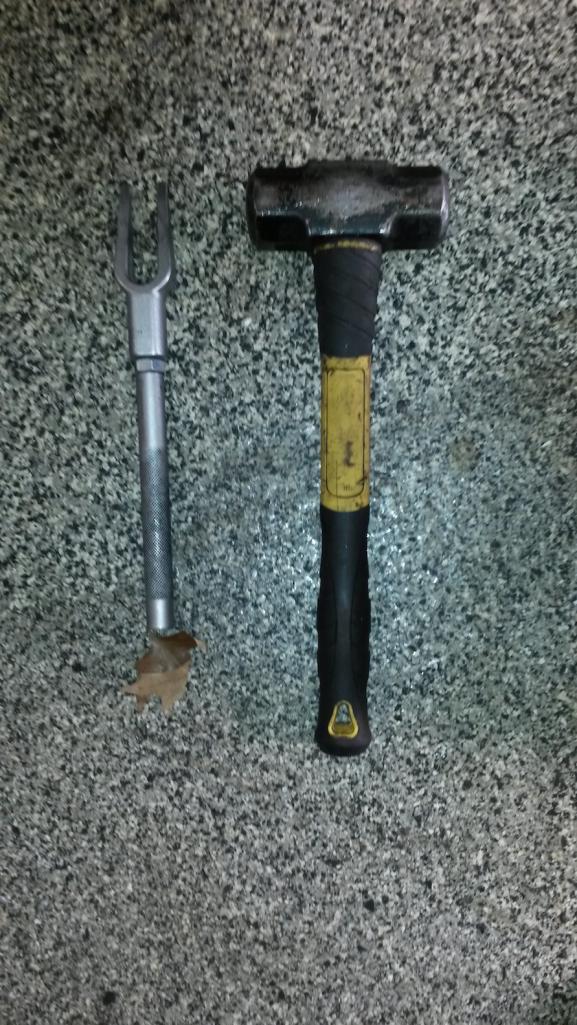 The tie rod separator is also referred to as a "pickle fork"... The only odd thing I found here was that the nut on the right side was a Nyloc-type, not the castle nut/cotter pin I expected. Not sure who did that or when--but it was in keeping with some of the other odd stuff I found when replacing the clutch last month. With the tie rod hanging down, I pushed the outer end of the old boot back (towards the center of the car) and off the retainer. Left the spring on the boot for safe keeping. I used the "group buy wrench" to loosen the boot retainer. 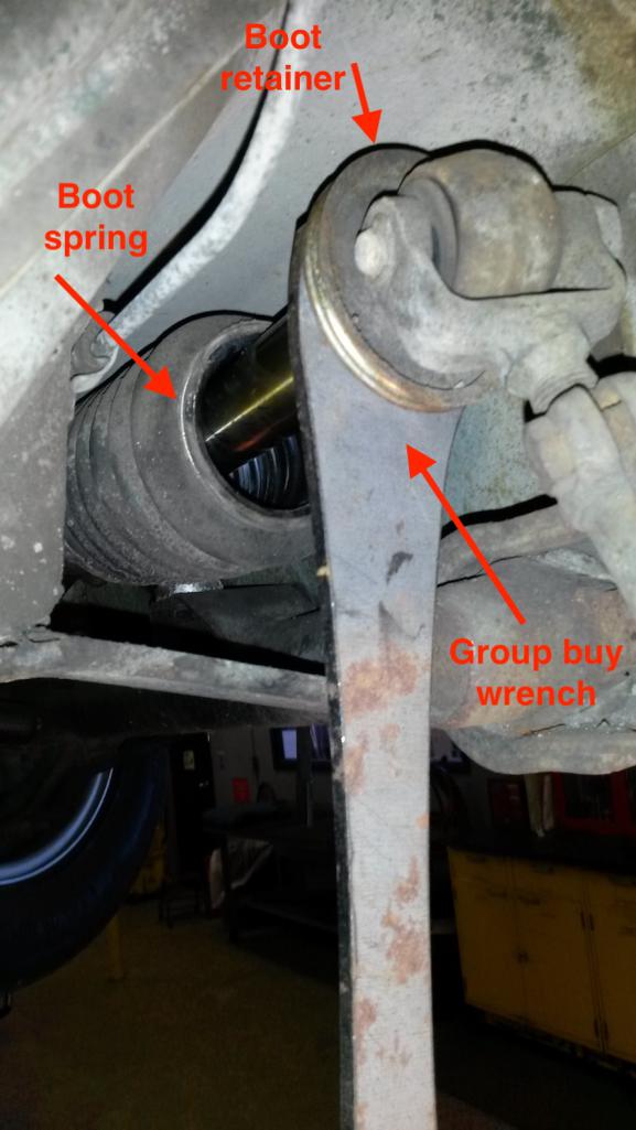 Another view... 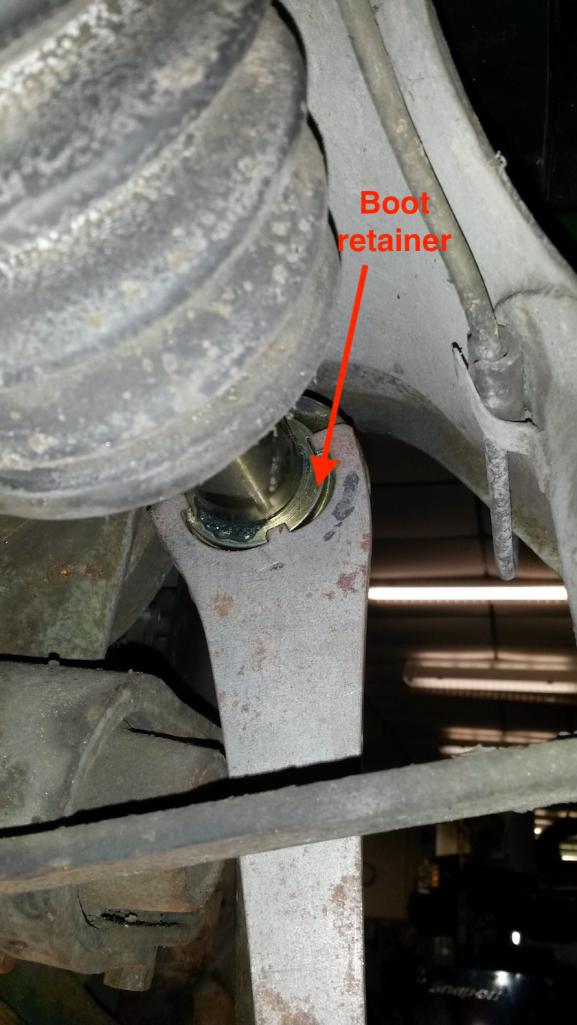 The wrench fit the boot retainer well and made loosening it easy. Observation: I think retaining the boot is only one function of this piece--given that the boot retainer is threaded and tightened to 51ft-lb (per Haynes, page 99), I think it also serves as a "jam nut" for the tie rod eye bolt. Too bad it wouldn't fit inside the new boot, or I'd have been tempted to reuse it instead of the new spacer. |
   |

 
|
  |
Replies
| anderssj |
Jan 12 2020, 10:46 PM
Post
#2
|
|
Dog is my copilot... Group: Members Posts: 1,650 Joined: 28-January 03 From: VA Member No.: 207 Region Association: MidAtlantic Region |
Doggone it--we got back from our drive and the power was out. Seems a tree limb dropped across a wire near here.
I meant to mention in the last post that I measured the length of the old tie rod (with the boot retainer threaded onto the eyebolt) from the rack side of the boot retainer to the center of the tie rod end (what Haynes calls the tie rod ball joint). Then I disassembled the new tie rod, slipped the boot on, and put on the new tie rod end. I adjusted its length so that when measured from the rack side of the spacer to the center of the tie rod ball joint, the new assembly matched the measurement of the old part. Sorry, should have taken a picture. FWIW, I put the boot on the assembly before I screwed it into the rack... As far as installing the boot, it went easier than I expected. I used glycerin as a lube, both around the outside of the rack housing and the inside of the boot. Highly recommended--glycerin is slicker than deer guts on a doorknob, and it won't harm the boot. I just kind of pushed and twisted/rotated the boot onto the rack housing (a little past where it is supposed to go) and it popped on. That said, I had to pull out on it with a pliers while easing it back down the rack housing a little to free part of the lip that had gotten tucked under. Once it was in place, I was able lift the retaining spring onto the lip with a small screw driver, then roll it on the rest of the way with my thumb (rotating the boot helps as you walk the retaining spring into place). 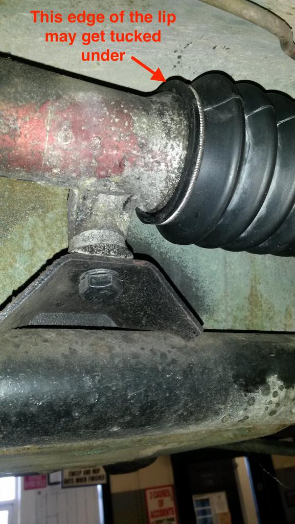 The outer end of the boot rides on a black rubber collar/disc on the tie rod. Once again, glycerin is your friend--used on the disc and on the inner lip of the boot. I pushed the boot lip onto the top of the disc with my thumb, then worked the rest of the onto the disc by pulling out on the boot with pliers while pushing the lip onto the disc. Sorry, it sounds more confusing than it really is... 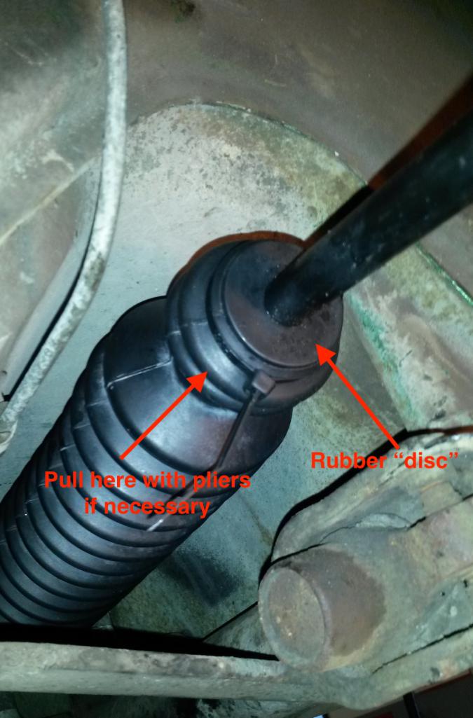 That said, it does take some pressure to get the boot in place. On the driver's side, I actually displaced the rubber disc a little; if that happens, just pull it back out the tie rod into the indentation where it belongs (indent is bare metal in this picture).  FWIW, this particular set of tie rods was shipped with two different sets of lock nuts instead of castle nuts--and the tie rod ball joints weren't drilled for cotter pins. I used the cone-shaped nut on the left, as it's the same type as used on our old Volvos--and if it's safe enough for Volvo, then it's safe enough for the 914 (IMG:style_emoticons/default/biggrin.gif) 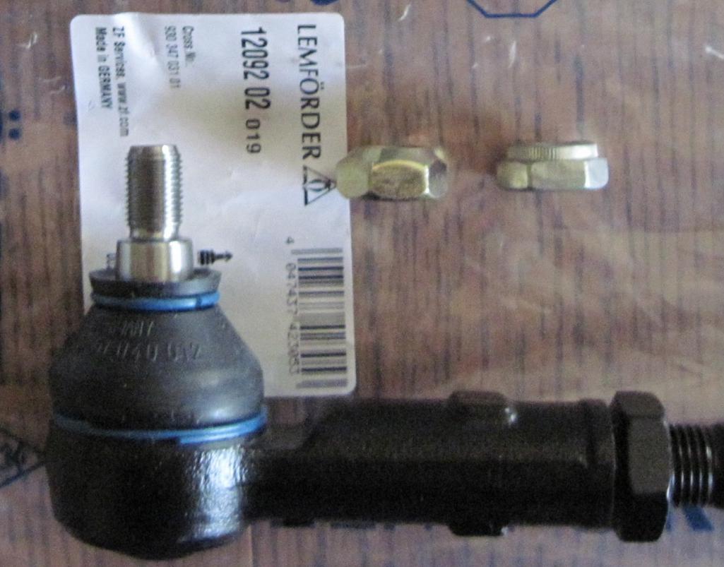 Because this type of lock nut its "pinched," it will only go freely on a couple of threads. Trying to screw it further onto the threaded shank of the tie rod end will just cause that shank to turn. However, by applying some upwards pressure from underneath the tie rod end, you can keep the threaded shank from turning while you install the nut. A hydraulic jack and a block of wood works nicely... 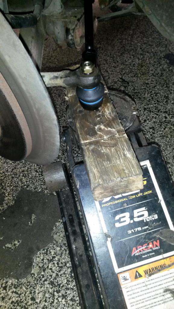 Torque the nut to 33 ft-lbs. Replace the wheel, and torque the wheel bolts to 108 ft-lbs. Funny, I'm having to split this write-up into 2 days just like the install. (IMG:style_emoticons/default/biggrin.gif) Attached thumbnail(s) 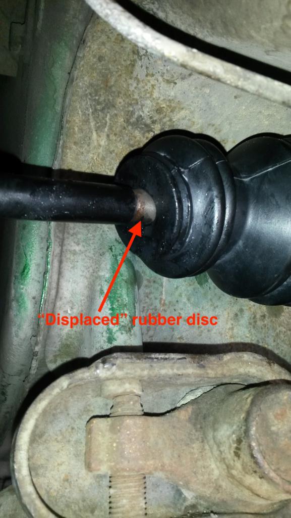
|
|
|
|
Posts in this topic
 anderssj Turbo Tie Rod Install Jan 12 2020, 12:10 PM
 anderssj And this is where the trouble began...
The next s... Jan 12 2020, 01:05 PM Montreal914 Nice write up, looking forward to the rest. :popc... Jan 12 2020, 01:48 PM Tdskip Nice job, thanks for posting Jan 12 2020, 03:38 PM cuddy_k Nicely done! Great details. Jan 13 2020, 12:15 AM soccerplyr Thanks for posting. I bought some recently and pla... Jan 13 2020, 07:56 PM
anderssj And this is where the trouble began...
The next s... Jan 12 2020, 01:05 PM Montreal914 Nice write up, looking forward to the rest. :popc... Jan 12 2020, 01:48 PM Tdskip Nice job, thanks for posting Jan 12 2020, 03:38 PM cuddy_k Nicely done! Great details. Jan 13 2020, 12:15 AM soccerplyr Thanks for posting. I bought some recently and pla... Jan 13 2020, 07:56 PM
 anderssj
Thanks for posting. I bought some recently and pl... Jan 14 2020, 08:51 AM anderssj OK, on the driver's side things went much bett... Jan 14 2020, 09:42 AM anderssj Almost forgot...check your car's alignment aft... Jan 14 2020, 11:26 AM
anderssj
Thanks for posting. I bought some recently and pl... Jan 14 2020, 08:51 AM anderssj OK, on the driver's side things went much bett... Jan 14 2020, 09:42 AM anderssj Almost forgot...check your car's alignment aft... Jan 14 2020, 11:26 AM |
1 User(s) are reading this topic (1 Guests and 0 Anonymous Users)
0 Members:

|
Lo-Fi Version | Time is now: 25th April 2024 - 07:11 AM |
Invision Power Board
v9.1.4 © 2024 IPS, Inc.