|
|
|
Porsche, and the Porsche crest are registered trademarks of Dr. Ing. h.c. F. Porsche AG.
This site is not affiliated with Porsche in any way. Its only purpose is to provide an online forum for car enthusiasts. All other trademarks are property of their respective owners. |
|
|

  |

| jfort |
 Feb 20 2020, 02:46 PM Feb 20 2020, 02:46 PM
Post
#1
|
|
Senior Member  Group: Members Posts: 1,135 Joined: 5-May 03 From: Findlay, OH Member No.: 652 Region Association: Upper MidWest |
I recently put in a new fuel tank (crud v new PMO’s issue). Last year I put in a new sender as I was having trouble getting accurate readings at the gauge. It worked better than it does now but was not very accurate. At least it would show “full”) That sender is now on the new tank. Unfortunately, I must have thrown out the old sender. So, now, the needle is at the bottom when the power is off. Turn on the juice and it snaps to a ¼ full – but it stays the same even when the tank is full.
I was given a fuel gauge to experiment with. See picture. There is a terminal for ground, one labelled “+” and another labelled “G”. Also, I have a 12v DC power source, a multimeter, and a 0-100 ohm variable resistor. I know that the sender is, in effect, a variable resistor and I think I’ve read here that it should show 75 ohms for a full tank and 5 ohms for an empty tank. Also, I vaguely remember from school, decades ago, that V=IR (and F=ma and “you can’t push a rope”). I see that there are 3 wires at the sender, brown for ground, black and green. Black goes to the bulb terminal? Green goes to the "G" terminal? Switched 12v to the "+" terminal? I’d like to isolate whatever the issue is and understand the problem and the fix. Shouldn’t I be able to wire up the outside gauge “in the lab” and make it go up and down by turning the pot? Can someone explain how I would do that with the tools I have? I’d like to test both gauges. Shouldn’t I be able to measure the resistance created by the sender? I’ll cut and terminalize the wires to measure and make a source for the in-car gauge, if necessary. How would I measure the resistance, green or black wire to ground? My car is a factory six, as is the wiring diagram, but the gauge is most likely from a 4, if that makes a difference. I think I have the tools I need to solve this problem, just not the smarts. Thanks in advance!! 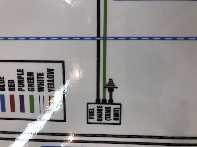 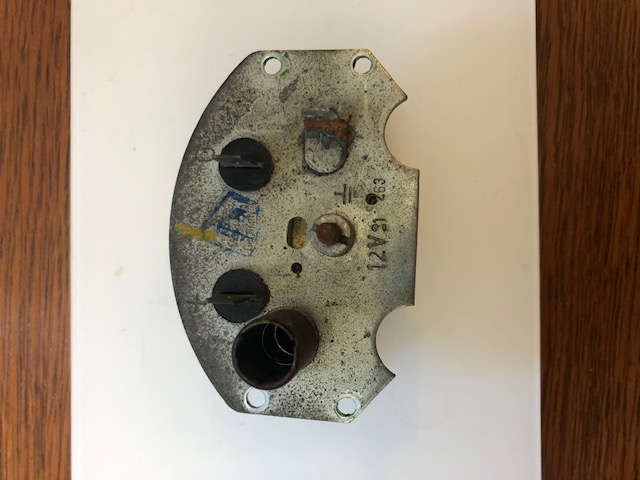  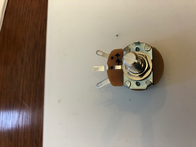 |
   |

 
|
| 914Sixer |
Feb 20 2020, 03:58 PM
Post
#2
|
|
914 Guru Group: Members Posts: 8,882 Joined: 17-January 05 From: San Angelo Texas Member No.: 3,457 Region Association: Southwest Region |
All the fuel gauges are the same regardless of -6 or -4. Not sure but I am thinking resistance is 90 ohms for full tank, have to check FSM.
|
|
|
|
|
1 User(s) are reading this topic (1 Guests and 0 Anonymous Users)
0 Members:

|
Lo-Fi Version | Time is now: 13th May 2024 - 07:51 PM |
Invision Power Board
v9.1.4 © 2024 IPS, Inc.