|
|
|
Porsche, and the Porsche crest are registered trademarks of Dr. Ing. h.c. F. Porsche AG.
This site is not affiliated with Porsche in any way. Its only purpose is to provide an online forum for car enthusiasts. All other trademarks are property of their respective owners. |
|
|


| 76-914 |
 Apr 17 2020, 04:38 PM Apr 17 2020, 04:38 PM
Post
#1
|
|
Repeat Offender & Resident Subaru Antagonist  Group: Members Posts: 13,502 Joined: 23-January 09 From: Temecula, CA Member No.: 9,964 Region Association: Southern California |
Like the title says............I'd have avoided this another year if possible. Heck, one was in pretty good shape anyway. (IMG:style_emoticons/default/beer.gif) I can't remember when I bought these from 914rubber but it was awhile back. Besides, some of my most serious screwups were the result of installing some random, inexpensive and simple part. (IMG:style_emoticons/default/mad.gif) I'm happy to say that, as I learned, this isn't terribly involved after all. I don't how long I spent but you should be able to this some Saturday morning, easy.
Jack up the front end and remove both tires. You can do this with the tires in place but I have a short temper and need all the room I can get. (IMG:style_emoticons/default/shades.gif) Disconnect the Neg battery cable. Remove the side reflector and lens assembly from fender. Cut and remove the old side lamp rubber boot and the main boot but leave the part surrounding the harness where it penetrates the fender. This protects the wires and acts as a 3rd hand later. The boot before & after : 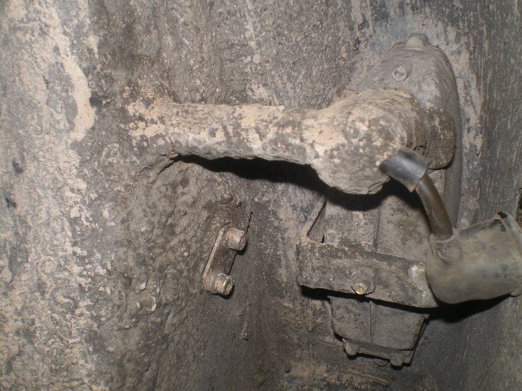 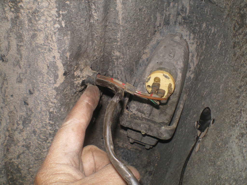 Mark and remove the wires from the bucket and remove the 10mm nut and attaching clamp. It gives that little bit of extra room that keeps me from going ballistic. (IMG:style_emoticons/default/biggrin.gif) 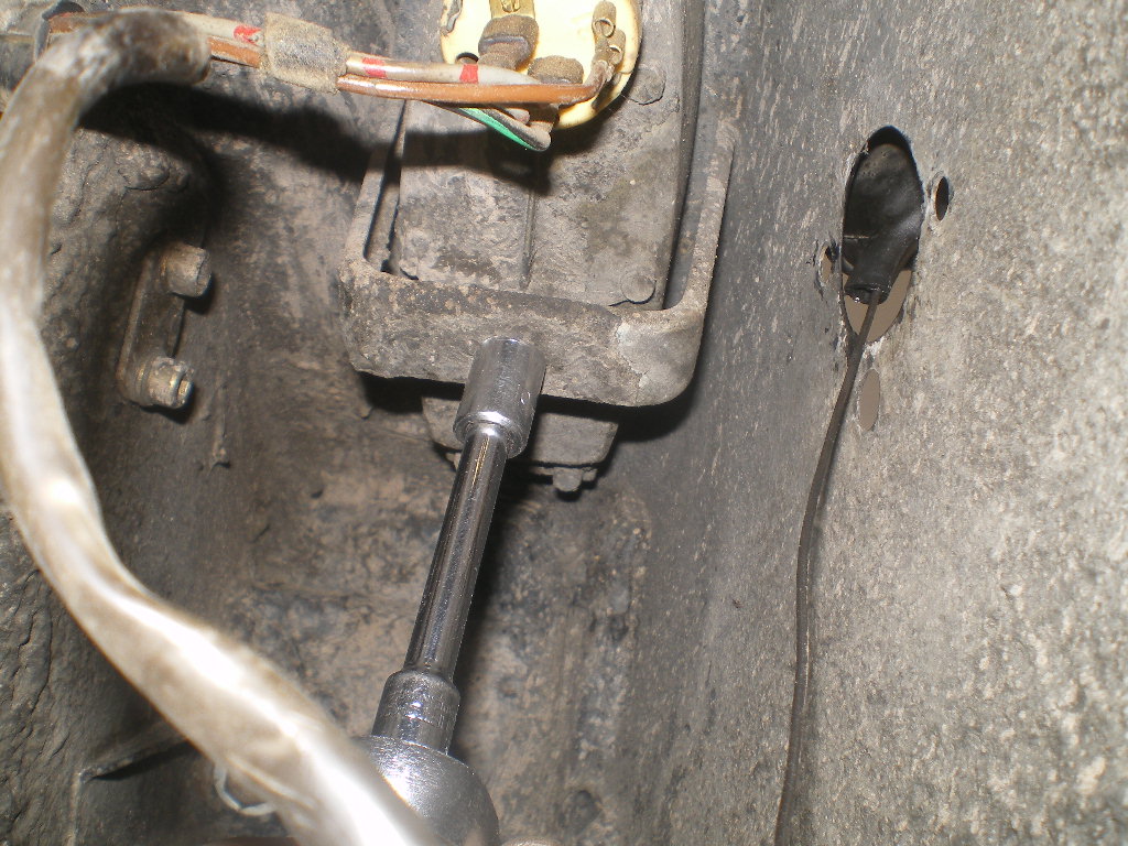 Then cut a piece of heat shrink tube about 2" long and slide one over each bundle of wires. 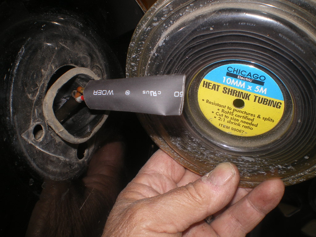 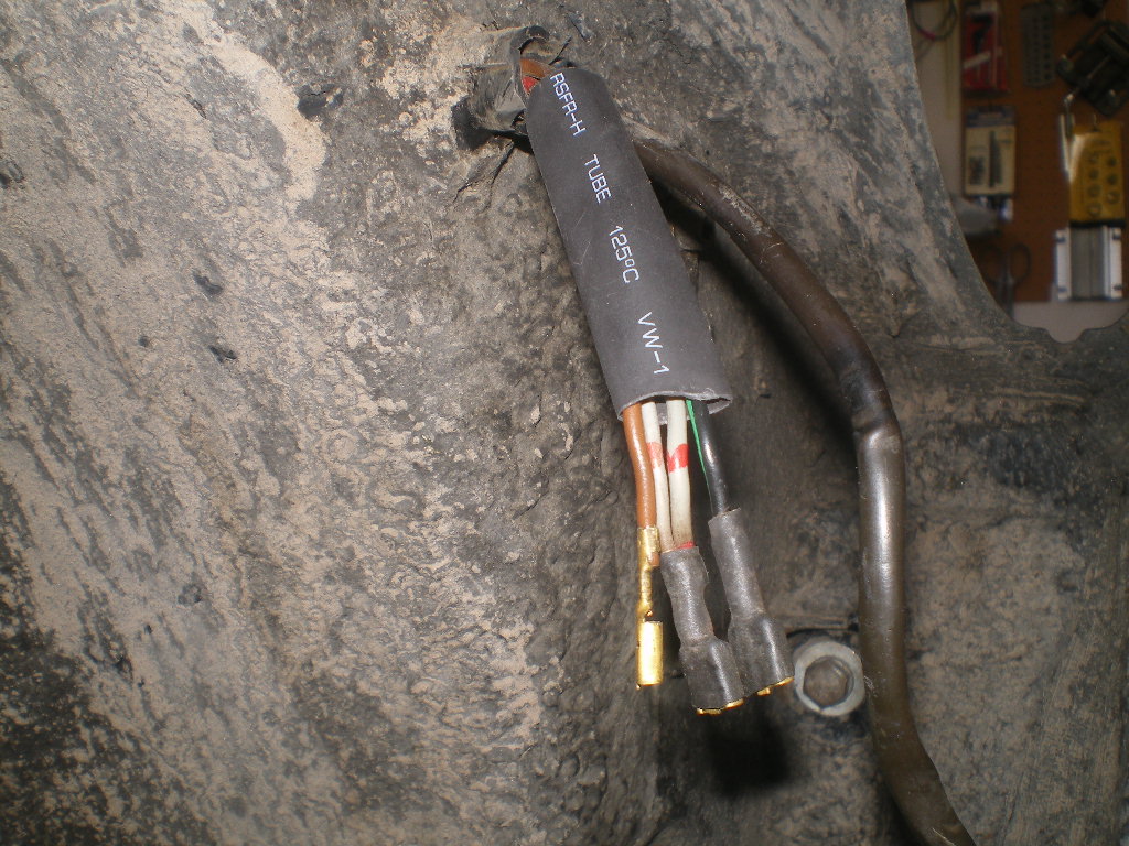 Cut 2 lengths of baling or copper wire appx 12" long. Take a very small tie wrap or safety wire and tie the wires together as shown below. This picture is actually a "fail" but it will give you the idea. Eventually I cut the clear tie wrap and hooked the wire around the red or lower one. Otherwise the wires would bunch up when pulled upon. The same is done to the side marker lead which only has 2 wires. Before you shrink the tube over the spade terminals be sure you line them up in a manner that produces the smallest diameter. Remember, this operation is akin to stretching a Gnat's Ass over a Rain Barrel and just like the Gnat we want to make that Rain Barrel as small as possible. 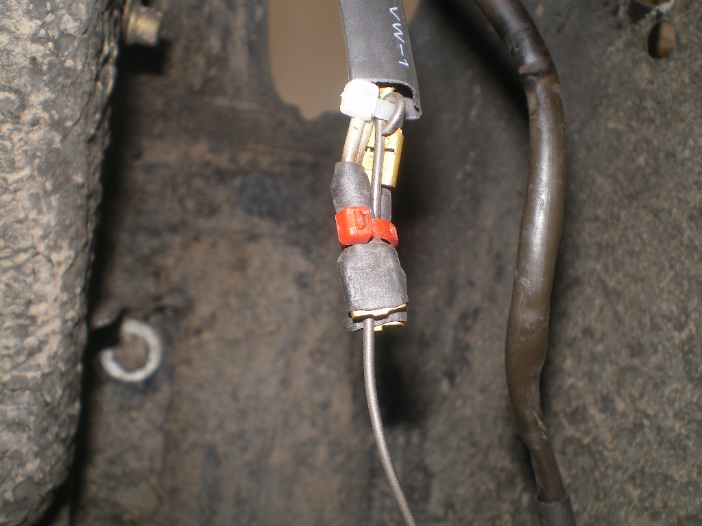 Before installing I placed a liberal amount of glycerine inside the "thru" section of the boot. 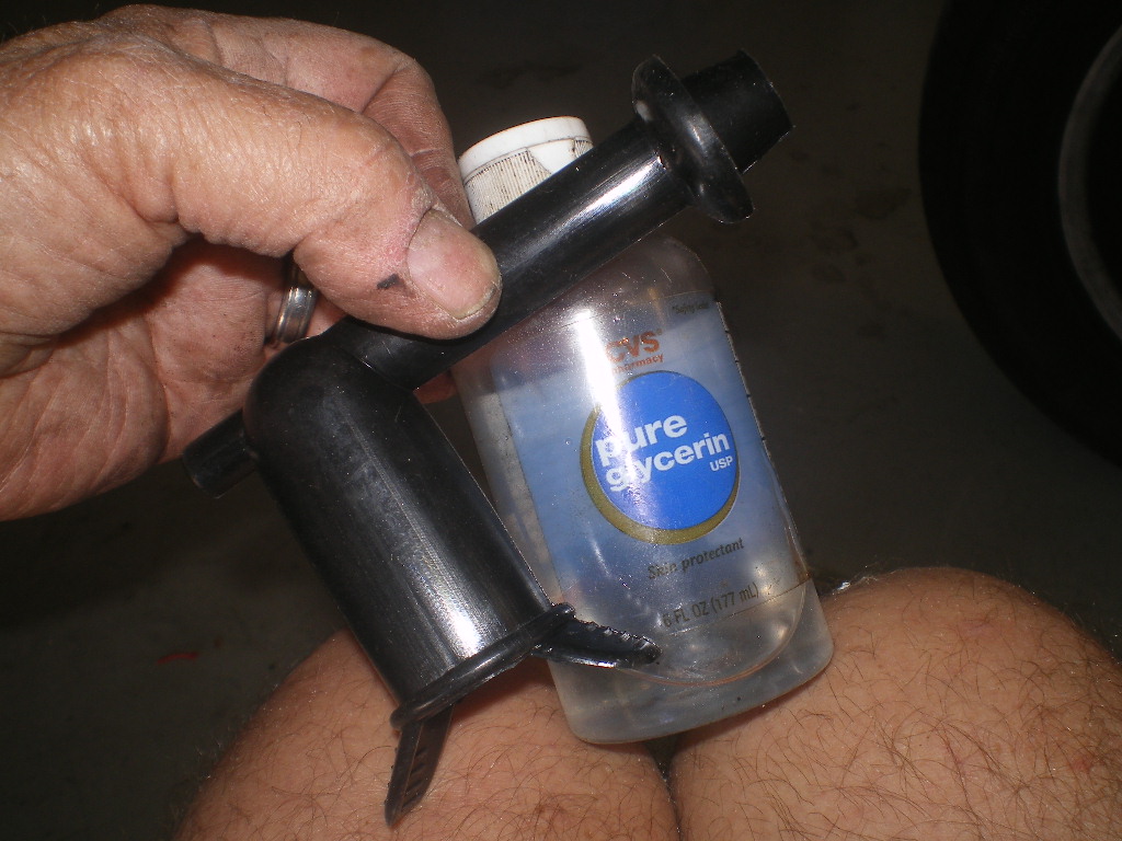 Next I fed both pull wires through the boot and out their respective openings. Take the wire attached to the side lamp (the lead with only 2 wires) and wrap the other end around something rigid and pull it taunt. You may tie to a drop link, like I did, or even a Zert fitting on the master cylinder. Refer to pic. Look closely and you can see the shrink wrapped wires that aren't inside the boot yet. These will be pulled in after the other section is pulled through. Clean the lube off your hands, grab the boot and pull it up the tie wire while maneuvering the boot as required. It may take a small pick to stretch the lip of the boot over some hump but it will pull through if you lubed the wires and boot well. Once this lead is pulled through & into place remove the shrink wrap, zip tie and pull wire. The 2nd wire which is connected to the 3 wire bundle is now pulled into the boot to the point that you can see the spades. It won't make the turn as configured so you'll need to remove the shrink wrap, zip tie and pull wire while it sits inside the boot. I used an Exacto knife to reach in while being careful not to knick a wire. Once this is cleaned up you can retrieve the wires with some needle nose pliers. 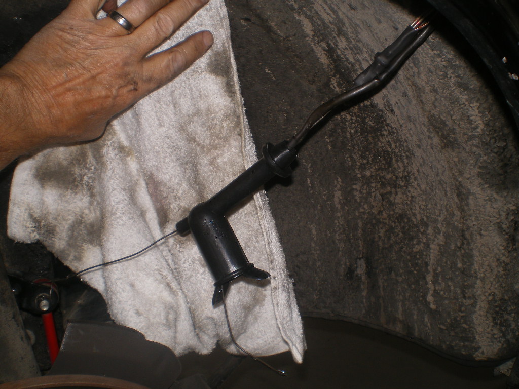 Don't install the side lens until you have the boot pulled over the lamp housing as you will need to reach in that hole to grab on of the rubber ears. I didn't Lub thesis I wanted it to stick and boy does it. It takes little effort but wound up with an excellent fit. Great product @Mikey914 . BONUS QUESTION: Who can spot the oddity in the 4th to last pic of the side marker lamp? 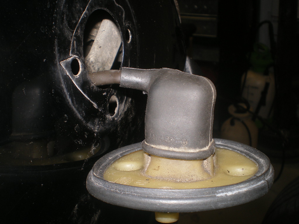 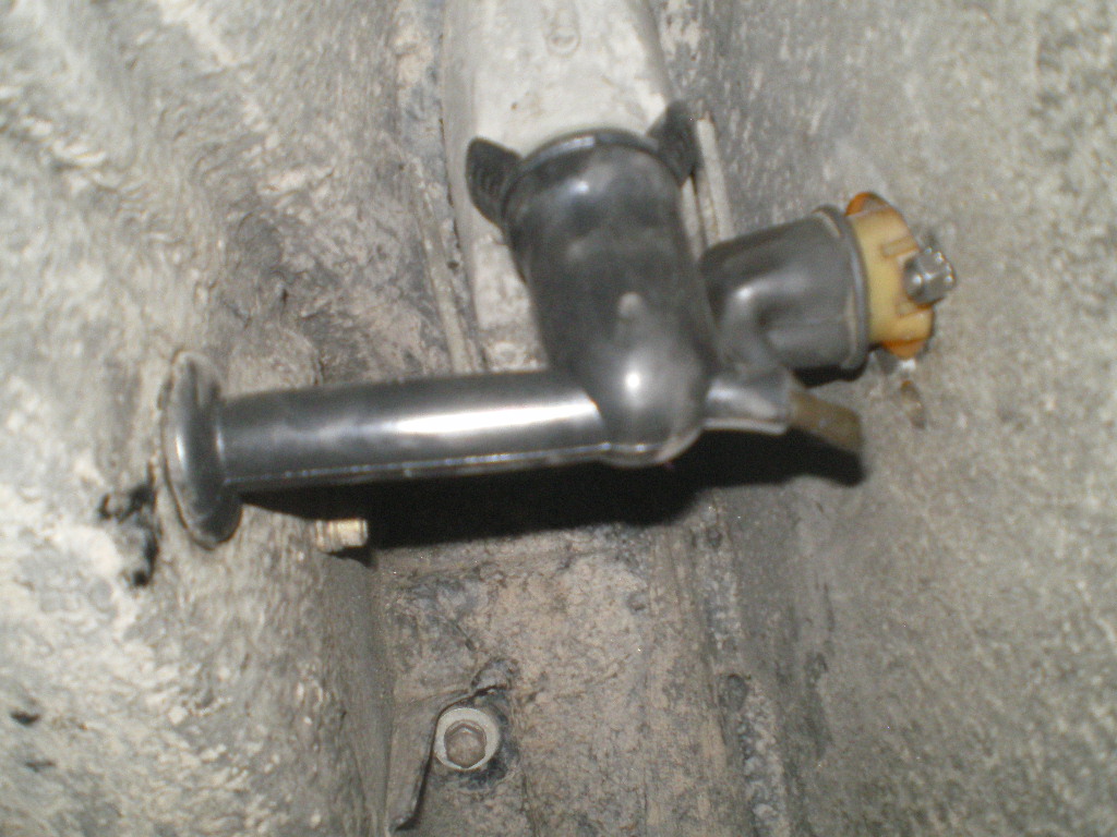 Attached image(s) 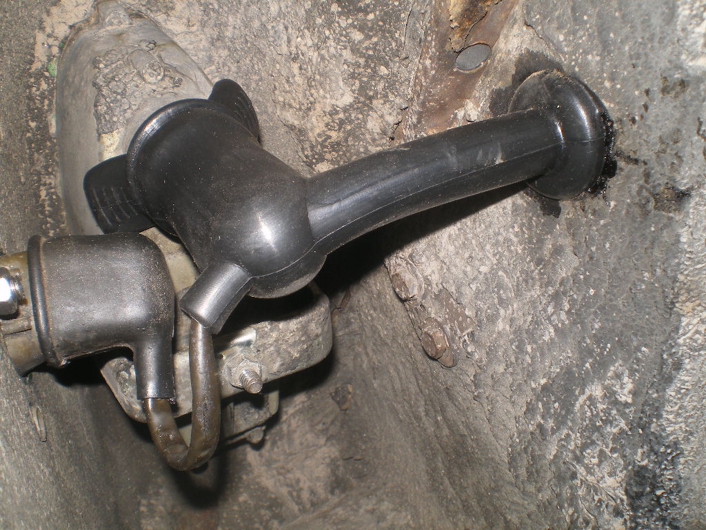 
|
   |

 
|
Posts in this topic
 76-914 Installing Front Turn Signal Boots Apr 17 2020, 04:38 PM
 Spoke Nice job. Not one of the fun projects on the 914. Apr 17 2020, 05:48 PM Mikey914 nice technique. Apr 17 2020, 06:43 PM rgalla9146 Following your instructions makes this very diffic... Apr 17 2020, 07:15 PM aharder wish I had this before I did mine. I cussed all ni... Apr 17 2020, 08:08 PM cary Must have been an electrician in his first life. Apr 17 2020, 11:38 PM bbrock I vote for this moving to classics so it is easy t... Apr 18 2020, 07:06 AM
 913B :trophy: :Qarl: :worship:
Great Job ! Anot... Apr 20 2020, 10:27 PM
913B :trophy: :Qarl: :worship:
Great Job ! Anot... Apr 20 2020, 10:27 PM  |
1 User(s) are reading this topic (1 Guests and 0 Anonymous Users)
0 Members:

|
Lo-Fi Version | Time is now: 19th May 2024 - 04:17 AM |
Invision Power Board
v9.1.4 © 2024 IPS, Inc.