|
|
|
Porsche, and the Porsche crest are registered trademarks of Dr. Ing. h.c. F. Porsche AG.
This site is not affiliated with Porsche in any way. Its only purpose is to provide an online forum for car enthusiasts. All other trademarks are property of their respective owners. |
|
|

  |

| Maroon Loon |
 Jun 2 2020, 04:16 PM Jun 2 2020, 04:16 PM
Post
#1
|
|
Newbie  Group: Members Posts: 1 Joined: 18-February 17 From: Portland, Oregon Member No.: 20,847 Region Association: Pacific Northwest |
Hello,
I am looking to replace signal relay # 914.618.303.11. Is there a place to purchase another one? I came across a URO model with is listed as a replacement version, although the pins are located differently. What do you think is the correct positioning / location pins from the OEM part to the URO? See photos Many Thanks, 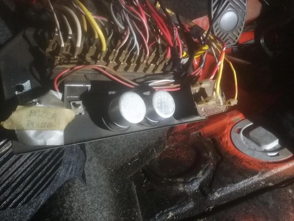 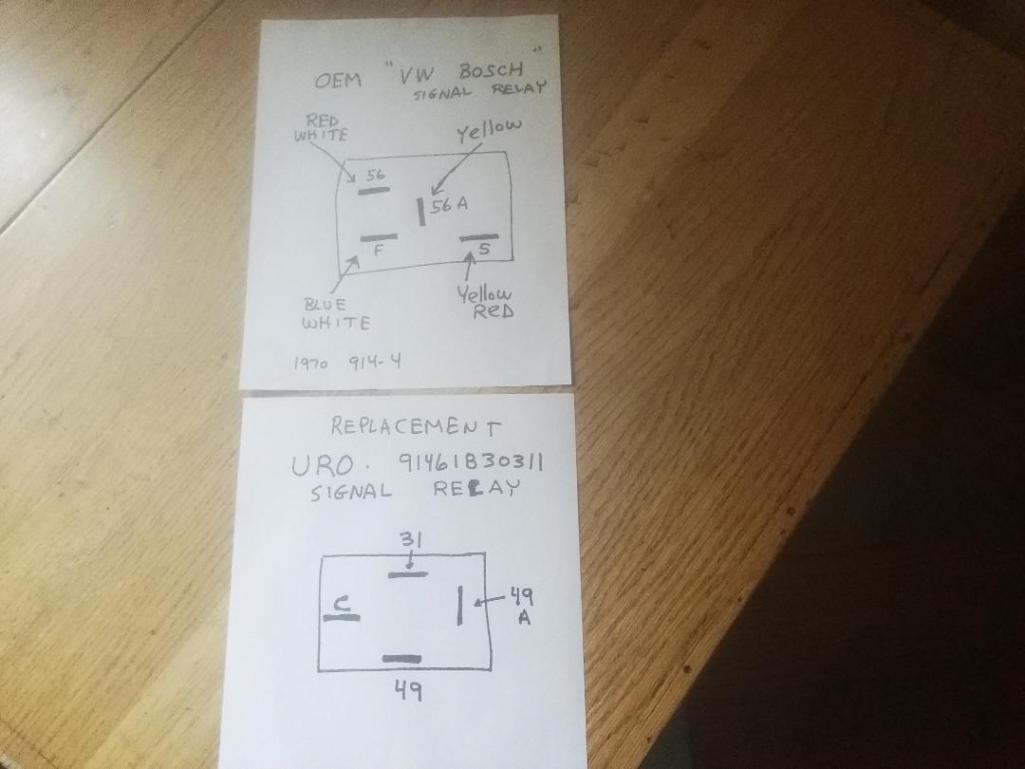 |
   |

 
|
| Spoke |
Jun 2 2020, 06:14 PM
Post
#2
|
|
Jerry Group: Members Posts: 6,972 Joined: 29-October 04 From: Allentown, PA Member No.: 3,031 Region Association: None |
(IMG:style_emoticons/default/welcome.png)
I believe the top relay pin layout is for the hi/lo beam selector relay. The lower relay pin layout is for the flasher relay. Universally available EP26 in many FLAPS is LED-compatible and pin compatible with the 914 OEM relay. A slight modification is needed for the K/C/C2 pin to drive the common connection of the tachometer turnsignal indicators. I resell modified EP26 flasher relays for the 914. |
|
|
|
| second wind |
Jun 2 2020, 06:55 PM
Post
#3
|
|
Senior Member Group: Members Posts: 847 Joined: 30-December 10 From: Los Angeles, California Member No.: 12,543 Region Association: Southern California |
QUOTE(Spoke @ Jun 2 2020, 05:14 PM)  (IMG:style_emoticons/default/welcome.png) I believe the top relay pin layout is for the hi/lo beam selector relay. The lower relay pin layout is for the flasher relay. Universally available EP26 in many FLAPS is LED-compatible and pin compatible with the 914 OEM relay. A slight modification is needed for the K/C/C2 pin to drive the common connection of the tachometer turnsignal indicators. I resell modified EP26 flasher relays for the 914. Hello Spoke...so now I see that you do sell the modified turn signal relays for 914's....I must have missed it earlier. Could you please post the link for the purchase of such a relay? Thank you very much. gg |
|
|
|
| Spoke |
Jun 2 2020, 07:06 PM
Post
#4
|
|
Jerry Group: Members Posts: 6,972 Joined: 29-October 04 From: Allentown, PA Member No.: 3,031 Region Association: None |
QUOTE(second wind @ Jun 2 2020, 08:55 PM) QUOTE(Spoke @ Jun 2 2020, 05:14 PM) (IMG:style_emoticons/default/welcome.png) I believe the top relay pin layout is for the hi/lo beam selector relay. The lower relay pin layout is for the flasher relay. Universally available EP26 in many FLAPS is LED-compatible and pin compatible with the 914 OEM relay. A slight modification is needed for the K/C/C2 pin to drive the common connection of the tachometer turnsignal indicators. I resell modified EP26 flasher relays for the 914. Hello Spoke...so now I see that you do sell the modified turn signal relays for 914's....I must have missed it earlier. Could you please post the link for the purchase of such a relay? Thank you very much. gg EP26 For 911, 914 '70-'73 (Separate R and L Indicators) EP26 For 914 '74-'76 (Single L/R Indicator) |
|
|
|
|
2 User(s) are reading this topic (2 Guests and 0 Anonymous Users)
0 Members:

|
Lo-Fi Version | Time is now: 20th April 2024 - 07:36 AM |
Invision Power Board
v9.1.4 © 2024 IPS, Inc.