|
|
|
Porsche, and the Porsche crest are registered trademarks of Dr. Ing. h.c. F. Porsche AG.
This site is not affiliated with Porsche in any way. Its only purpose is to provide an online forum for car enthusiasts. All other trademarks are property of their respective owners. |
|
|


| Retroracer |
 Jun 10 2020, 09:40 PM Jun 10 2020, 09:40 PM
Post
#1
|
|
Senior Member  Group: Members Posts: 612 Joined: 7-July 13 From: Bend OR Member No.: 16,100 Region Association: Pacific Northwest |
So I posted some stuff on this project already - on the "shelter in place" project thread - but thought I'd summarize here.
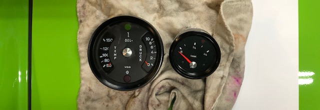
The goal was to fabricate replicas of two of the GT factory gauges - Oil pressure and temp, and the 66mm fuel gauge. Real ones, as you may imagine are pretty rare, collectable and fetch high dollar amounts. FUEL GAUGE So I found an 80's 60mm VDO fuel gauge NOS on eBay - which I bought for for $32. Wrong fascia, no "empty" light - but the casing, bezel and glass form a good basis. As you may know, the 914/6 GT cars used a black faced, chrome dot, 60mm VDO fuel gauge with an "empty" indicator. It looks way cool and is one of those collection of things that people in the know will look for as they glance into any GT cockpit, to see how far the owner/builder went in their search to be truthful to the factory cars. I've seen recreations of these listed for $1500 on eBay. Which is ridiculous. In order to duplicate this piece from what I had, I needed to: - change the fascia from white to black, with correct lettering / ticks - change the black dot indicator to chrome dot - add a second bulb assembly for the EMPTY indicator - change the electrical working range from 0-180 ohms to the 914 sender (70-0ohms) - paint the internal bezel ring black pics of the process follow: 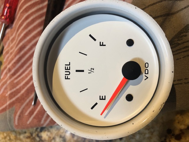 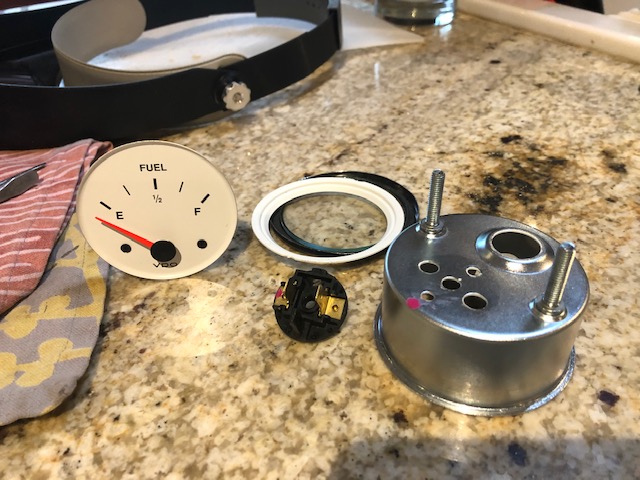 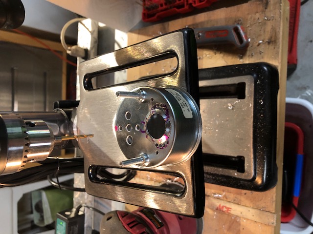 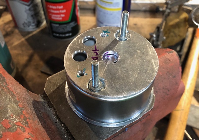 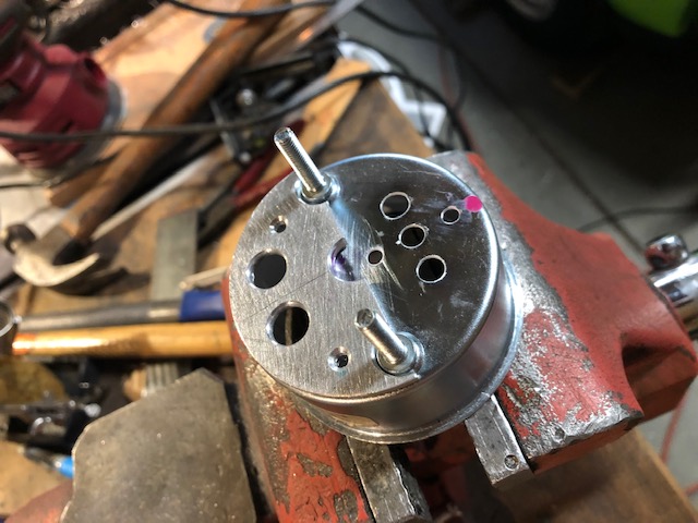 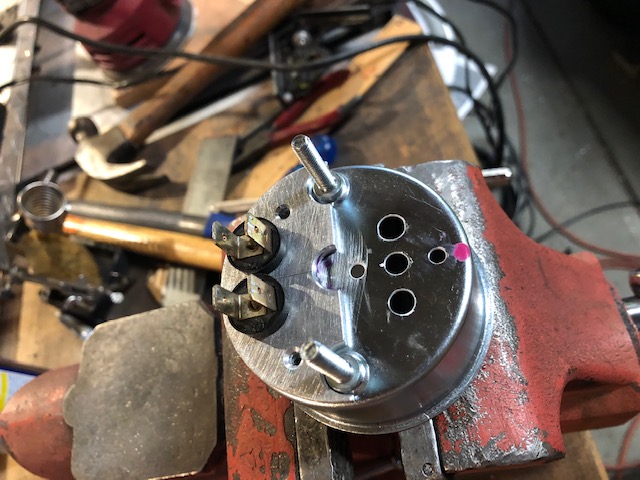 Also for reference this is the VDO part number on the core: 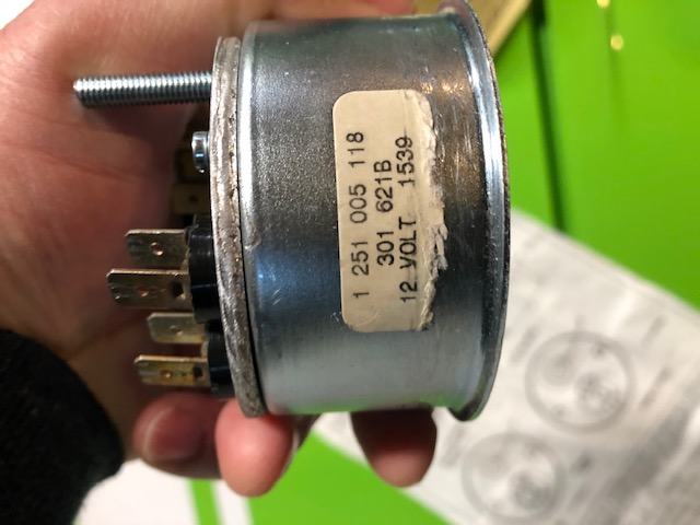 With the casing basically done, I drew the fascia in PowerPoint, copying the fonts, tick marks, etc. then sent a out PDF to have a vinyl sticker printed and mailed to me. Seems a little ghetto, but it came out OK: 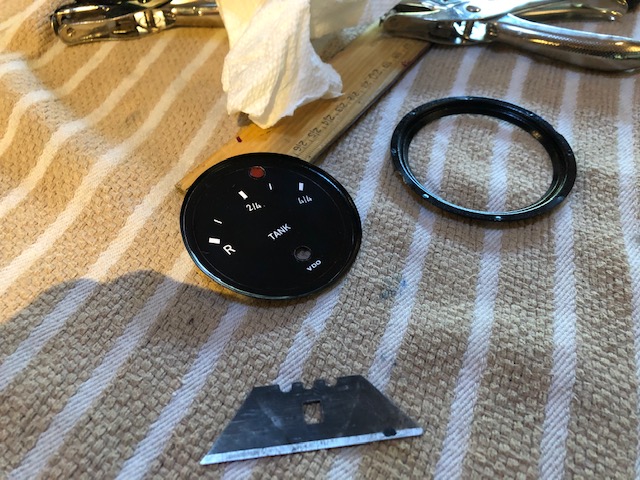 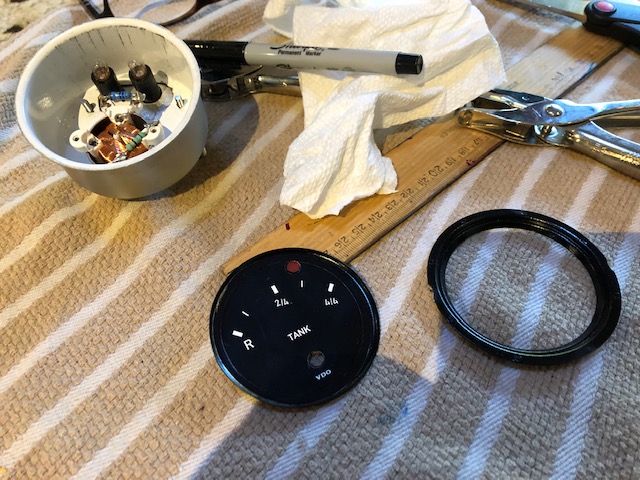 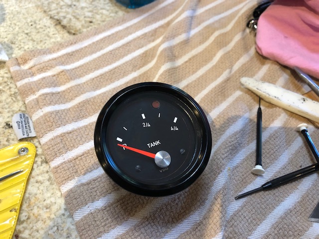 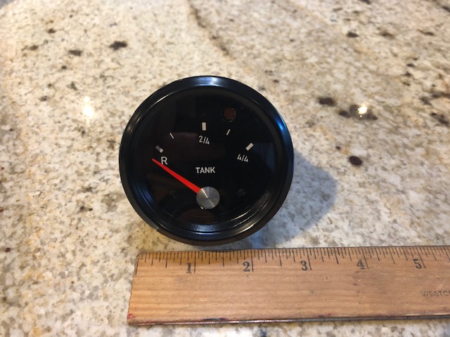 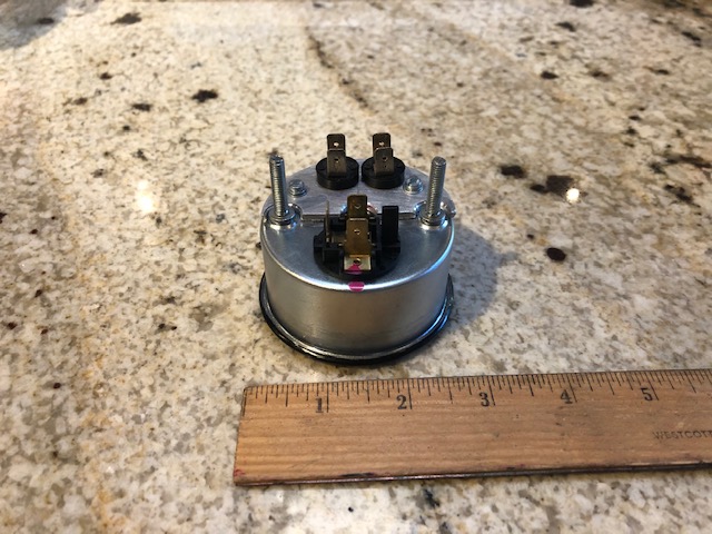 - Tony |
   |

 
|
  |
Replies(1 - 19)
| horizontally-opposed |
Jun 10 2020, 09:54 PM
Post
#2
|
|
Advanced Member Group: Members Posts: 3,432 Joined: 12-May 04 From: San Francisco Member No.: 2,058 Region Association: None |
Love details like these. Nicely done!
|
|
|
|
| Retroracer |
Jun 10 2020, 09:55 PM
Post
#3
|
|
Senior Member Group: Members Posts: 612 Joined: 7-July 13 From: Bend OR Member No.: 16,100 Region Association: Pacific Northwest |
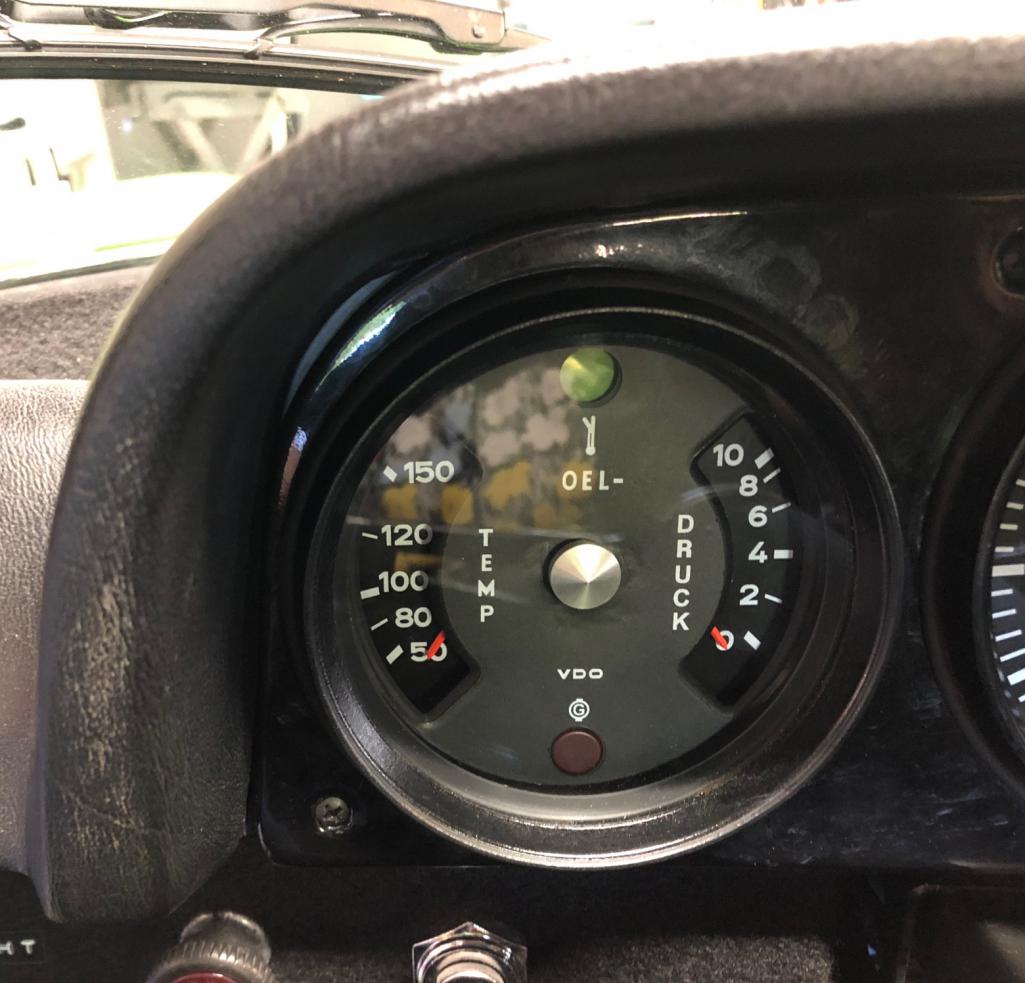
OIL PRESSURE / TEMP
I purchased a 911 oil gauge from a member here on the world; nice condition and out of a Sportomatic optioned vehicle. The gauges tested functional, the only detail is that the fascia and gauge scales were incorrect for the GT version. These items were secured from Heiler in Germany; then it becomes a simple reassembly task (no casing mods, or electronic mods like with the fuel gauge). Pictures show progress: 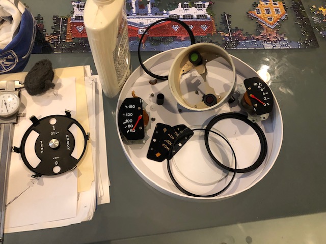 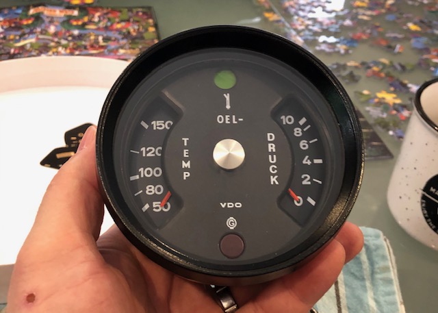 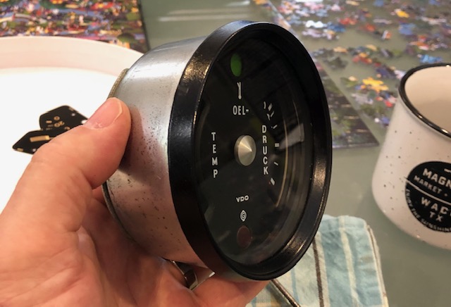 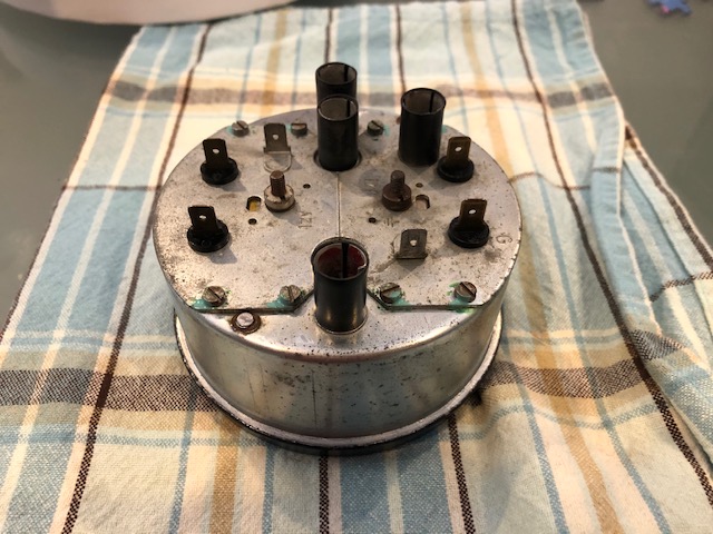 I needed a different sender to match the gauge, as my previous one only had the pressure switch, not the combo switch/sender. North Hollywood Speedometer were awesome in identifying the correct VDO sender and shipping it the same day. Good to go. - Tony |
|
|
|
| Retroracer |
Jun 10 2020, 10:05 PM
Post
#4
|
|
Senior Member Group: Members Posts: 612 Joined: 7-July 13 From: Bend OR Member No.: 16,100 Region Association: Pacific Northwest |
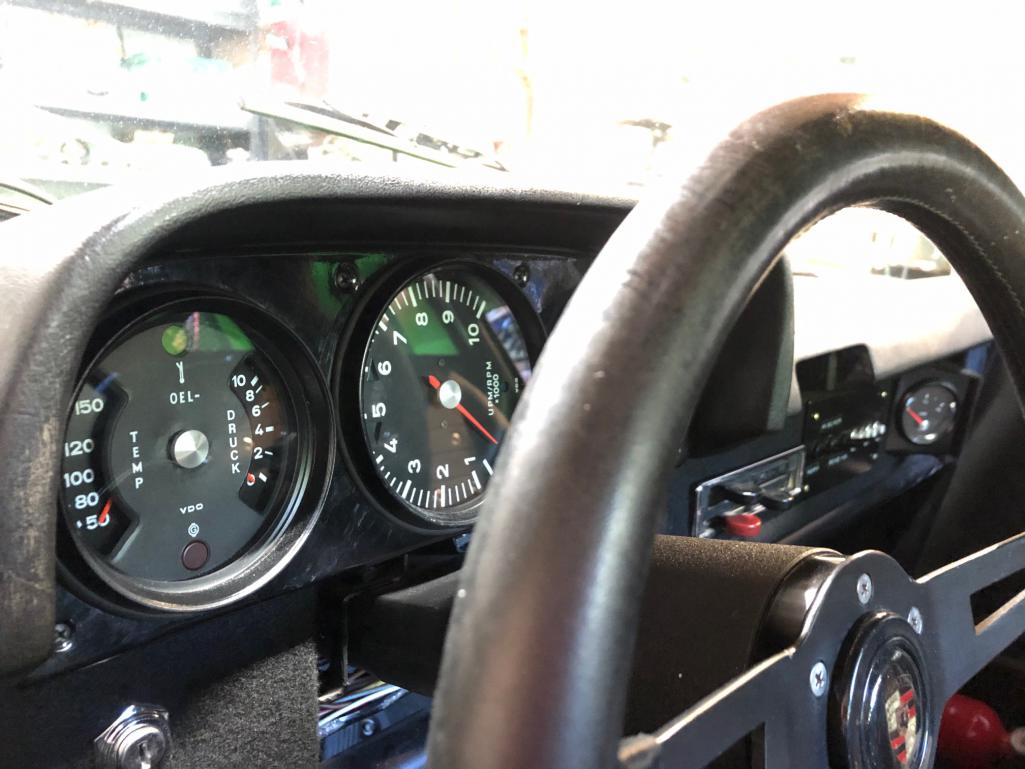
I had to make up a cowling to position the fuel gauge. I went back and forth on where to mount it - the factory GTs had several options - but I decided on having it peek out of the glove box area, as it meant the least disruption to the dash and the existing switch gear / circuit breakers.
Some CAD (Cardboard Aided Design), aluminum sheet and some matching black felt covering that I had left over from when I did the dash: 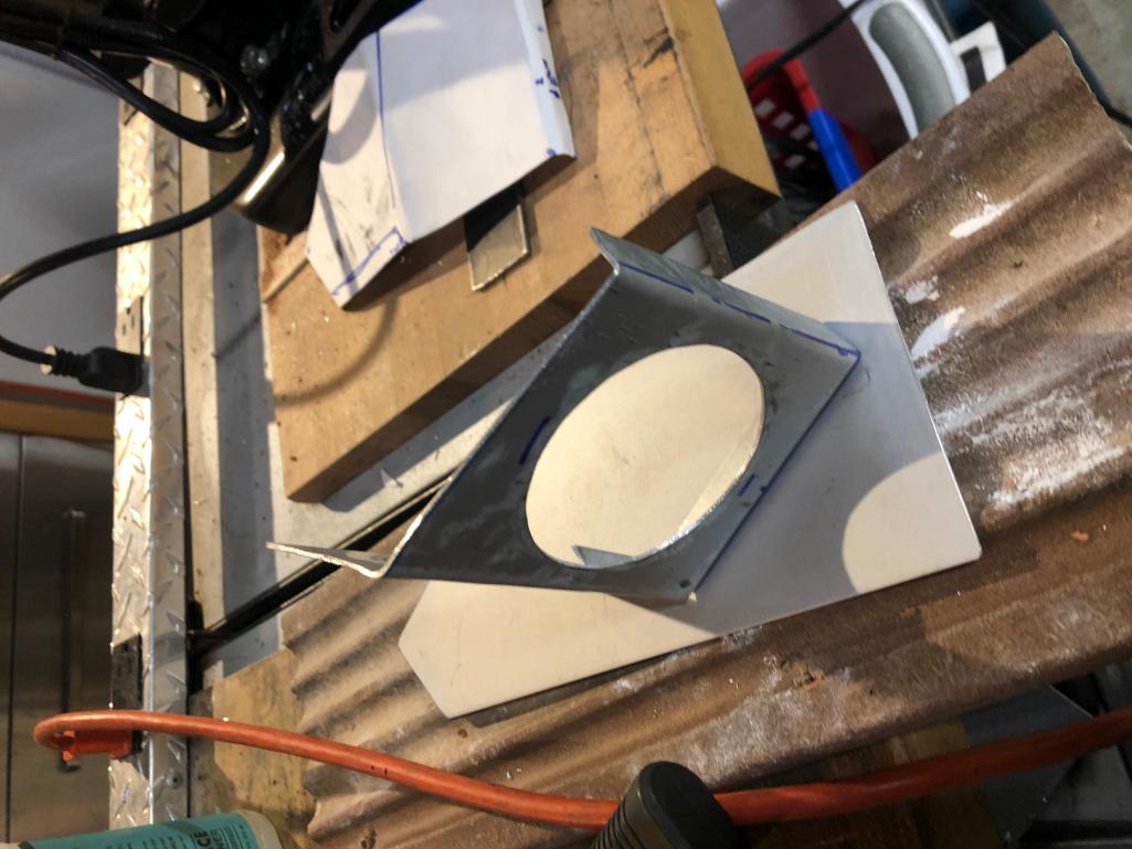 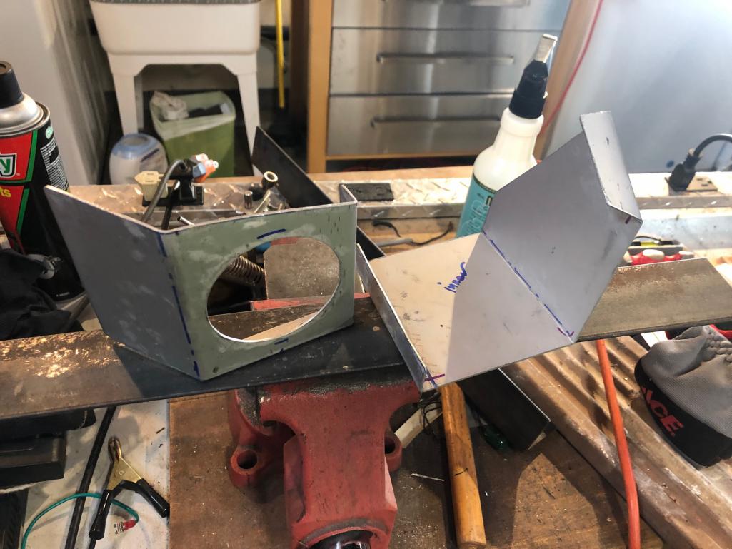 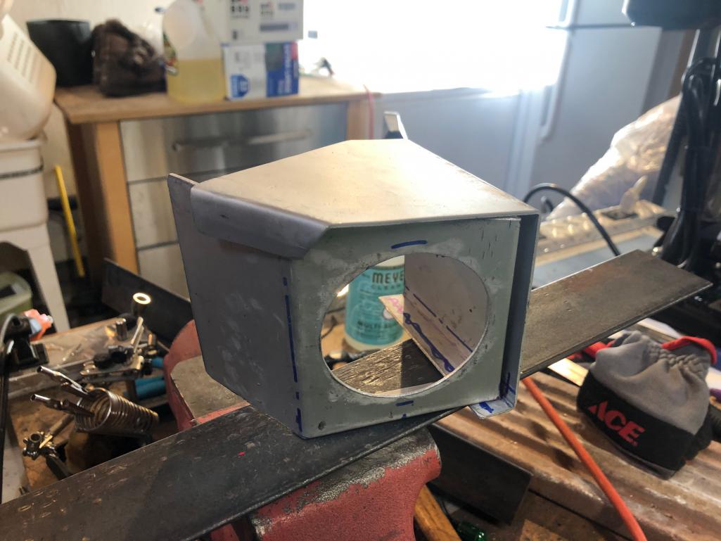 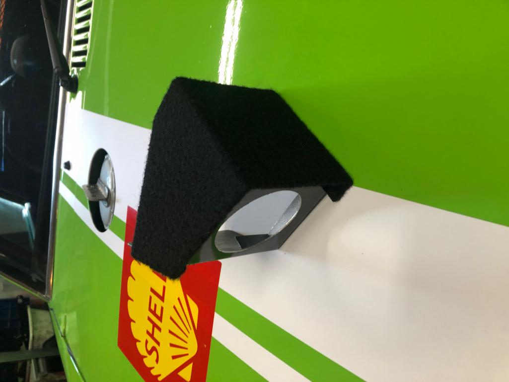 - Tony |
|
|
|
| Retroracer |
Jun 10 2020, 10:08 PM
Post
#5
|
|
Senior Member Group: Members Posts: 612 Joined: 7-July 13 From: Bend OR Member No.: 16,100 Region Association: Pacific Northwest |
...and in the car:
   - Tony |
|
|
|
| Cairo94507 |
Jun 11 2020, 06:42 AM
Post
#6
|
|
Michael Group: Members Posts: 9,762 Joined: 1-November 08 From: Auburn, CA Member No.: 9,712 Region Association: Northern California |
Great looking gauges Tony. (IMG:style_emoticons/default/beerchug.gif)
|
|
|
|
| Retroracer |
Jun 11 2020, 07:59 AM
Post
#7
|
|
Senior Member Group: Members Posts: 612 Joined: 7-July 13 From: Bend OR Member No.: 16,100 Region Association: Pacific Northwest |
@Cairo94507 @horizontally-opposed
Thanks guys! Also if anyone has questions or wants help/hints about how to work on these wonderful VDO units, feel free to ping me. For instance, I don't have any special tools to remove/replace the bezels, but I have arrived at a technique that works without excessive damage or deformation, - Tony |
|
|
|
| betz |
Jun 11 2020, 02:36 PM
Post
#8
|
|
Member Group: Members Posts: 76 Joined: 22-October 18 From: San Leandro, CA Member No.: 22,593 Region Association: Northern California |
How did you do the 10k RPM Tach? I'm planning on putting in an engine with an 8300 RPM redline.. eventually haha.
|
|
|
|
| Retroracer |
Jun 11 2020, 03:10 PM
Post
#9
|
|
Senior Member Group: Members Posts: 612 Joined: 7-July 13 From: Bend OR Member No.: 16,100 Region Association: Pacific Northwest |
@betz : Original thread to make your own:
http://www.914world.com/bbs2/index.php?sho...amp;hl=10K+tach I've since made (and sold on) a small batch of similar ones: http://www.914world.com/bbs2/index.php?sho...amp;hl=10K+tach There was significant interest from various folks on here after I sold these; I may be tempted to do another batch at some future point. FYI. - Tony |
|
|
|
| betz |
Jun 11 2020, 06:59 PM
Post
#10
|
|
Member Group: Members Posts: 76 Joined: 22-October 18 From: San Leandro, CA Member No.: 22,593 Region Association: Northern California |
QUOTE(Retroracer @ Jun 11 2020, 02:10 PM)  @betz : Original thread to make your own: http://www.914world.com/bbs2/index.php?sho...amp;hl=10K+tach I've since made (and sold on) a small batch of similar ones: http://www.914world.com/bbs2/index.php?sho...amp;hl=10K+tach There was significant interest from various folks on here after I sold these; I may be tempted to do another batch at some future point. FYI. - Tony Wow, that's really cool. I will be referencing this in the future most likely. Although, mine would be a 4 Cylinder and I'm not sure what kind of signals I'll be dealing with (but to my understanding most tachs operate in the same way). Thank you! |
|
|
|
| rgalla9146 |
Jun 11 2020, 07:33 PM
Post
#11
|
|
Advanced Member Group: Members Posts: 4,554 Joined: 23-November 05 From: Paramus NJ Member No.: 5,176 Region Association: None |
QUOTE(Retroracer @ Jun 11 2020, 05:10 PM) @betz : Original thread to make your own: http://www.914world.com/bbs2/index.php?sho...amp;hl=10K+tach I've since made (and sold on) a small batch of similar ones: http://www.914world.com/bbs2/index.php?sho...amp;hl=10K+tach There was significant interest from various folks on here after I sold these; I may be tempted to do another batch at some future point. FYI. - Tony Hello Tony In interested in a GT fuel gauge. I'm waiting for a gauge and donor parts to be delivered, some may be suitable for your conversion. Please include me in your list of prospects. Thank you Rory |
|
|
|
| 914forme |
Jun 11 2020, 07:42 PM
Post
#12
|
|
Times a wastin', get wrenchin'! Group: Members Posts: 3,896 Joined: 24-July 04 From: Dayton, Ohio Member No.: 2,388 Region Association: None |
@Betz , Tony is using a Bosch / Sunpro tach as his source for the conversion. Nice thing is the Tach has a switch that allows you to select 4, 6, 8 cylinder cars. What that does mean is if yours is going to be 4 you will still want to go and test and make sure it is accurately hitting the numbers you expect on the new 10K face.
BTW, Tony great job - @rgalla9146 Rory, this was the gauge I was telling you about. |
|
|
|
| betz |
Jun 12 2020, 10:21 AM
Post
#13
|
|
Member Group: Members Posts: 76 Joined: 22-October 18 From: San Leandro, CA Member No.: 22,593 Region Association: Northern California |
That's absolutely perfect. Now is just a question of gauge faces... does anyone in the US make them? Or just that german site?
I would ideally like a tach where 0 RPM starts at 6 o clock, but in the font and style of classic 914/911 gauges. And I'd probably want the red line too. Not trying to make a replica car or anything. (although if I did... it'd probably be an 11k RPM tach heheh) |
|
|
|
| Mueller |
Jun 12 2020, 10:34 AM
Post
#14
|
|
914 Freak! Group: Members Posts: 17,146 Joined: 4-January 03 From: Antioch, CA Member No.: 87 Region Association: None |
Great looking parts and nice attention to detail.
|
|
|
|
| davesprinkle |
Jun 12 2020, 10:05 PM
Post
#15
|
|
Senior Member Group: Members Posts: 720 Joined: 13-October 04 From: Berkeley, CA Member No.: 2,943 Region Association: None |
Retroracer, nice work. Can you describe the circuit mods required to work with the 914 sender and also to drive the low-fuel lamp?
|
|
|
|
| Retroracer |
Jun 13 2020, 08:19 AM
Post
#16
|
|
Senior Member Group: Members Posts: 612 Joined: 7-July 13 From: Bend OR Member No.: 16,100 Region Association: Pacific Northwest |
QUOTE(davesprinkle @ Jun 12 2020, 09:05 PM) Retroracer, nice work. Can you describe the circuit mods required to work with the 914 sender and also to drive the low-fuel lamp? Thanks Dave. The "empty" indicator was just metal work; in that the existing gauge just had a single rear illumination bulb holder - so I opened out that space in the casing, then made up a rear cover which housed two VDO bulb holders side by side. One of these is used as the back light illumination, then I drilled a hole in the fascia to align with the second one, so that acts as the "empty" indicator (check the pics for the casing mods and backplate fab, using 3mm aluminum). The stock 914 wiring loom then connects to both bulbs. I put some rubber tube around the "empty" bulb holder to shroud the light internally (and to stop the back light leaking through). Some red acrylic behind the fascia hole, and it matches the factory gauge appearance nicely. The sender was more of a pain. The 914 resistive tank sender is basically 0ohms full, 70ohms empty. That particular gauge expected 200ohms full, 0ohms empty..! So as well as the different resistance, there was some inversion of full/empty needed! I briefly thought about mounting the fuel tank upside down.... But really, I designed a circuit which sits between the sender and the gauge, based around a couple of transistors, to effectively invert the full/empty resistance function as seen by the gauge, as well as tweak the "effective" resistance range. Basically an analog inverter. It works OK - if I was doing it again I'd probably change up the circuit a bit, to improve the "near empty" linearity/performance. If you want the schematic (and feel a VDO fuel gauge construction urge) then shoot me a PM. I did look to see if I could obtain a sender to match the gauge; no luck though. On their parts site, VDO list some senders, but the only one with the correct polarity and range had no "empty" indicator. I like me the "empty" indicator. - Tony |
|
|
|
| mlindner |
Jun 13 2020, 10:52 AM
Post
#17
|
|
Senior Member Group: Members Posts: 1,522 Joined: 11-November 11 From: Merrimac, WI Member No.: 13,770 Region Association: Upper MidWest |
Tony, would you make the fuel gauge for sale? Mark
|
|
|
|
| Retroracer |
Jun 13 2020, 11:40 AM
Post
#18
|
|
Senior Member Group: Members Posts: 612 Joined: 7-July 13 From: Bend OR Member No.: 16,100 Region Association: Pacific Northwest |
QUOTE(mlindner @ Jun 13 2020, 09:52 AM) Tony, would you make the fuel gauge for sale? Mark Mark - Don't think its practical. The 60mm fuel gauges are pretty rare anyway; there are some 24V versions floating around on eBay sometimes, but they look to have the wrong needle design to match the GT Gauge. Basically I got lucky on finding that NOS item with the Miami Vice fascia. Doing small batches of the tach conversion is viable only as the donors are more plentiful. I hear you that there MAY be a market opportunity here.....! - Tony |
|
|
|
| davesprinkle |
Jun 14 2020, 10:59 AM
Post
#19
|
|
Senior Member Group: Members Posts: 720 Joined: 13-October 04 From: Berkeley, CA Member No.: 2,943 Region Association: None |
QUOTE(Retroracer @ Jun 13 2020, 07:19 AM) The sender was more of a pain. The 914 resistive tank sender is basically 0ohms full, 70ohms empty. That particular gauge expected 200ohms full, 0ohms empty..! So as well as the different resistance, there was some inversion of full/empty needed! I briefly thought about mounting the fuel tank upside down.... But really, I designed a circuit which sits between the sender and the gauge, based around a couple of transistors, to effectively invert the full/empty resistance function as seen by the gauge, as well as tweak the "effective" resistance range. Basically an analog inverter. It works OK - if I was doing it again I'd probably change up the circuit a bit, to improve the "near empty" linearity/performance. If you want the schematic (and feel a VDO fuel gauge construction urge) then shoot me a PM. I did look to see if I could obtain a sender to match the gauge; no luck though. On their parts site, VDO list some senders, but the only one with the correct polarity and range had no "empty" indicator. I like me the "empty" indicator. - Tony Tony, cool. I've got my meters pulled apart right now. It all started because my voltmeter was inaccurate. (Long story shortened, lamp currents were causing an IR-drop error on the sense leads. I severed the common gnd connection and added a separate lamp return lead. Now much more accurate, well within 0.2V.) Going into this surgery, I was under the impression that a 90 degree air-core meter movement would only have 1 coil. Wrong. The VDO meters have two coils, one of which is driven continuously through a resistor and/or discrete choke. This continuously driven coil is in parallel with what I'll call the active coil, which is in series with the resistive sensor (pressure sender, temp sender, tank sender, etc.) I'm not sure what the second coil is intended to do. Maybe linearize the meter movement somehow? And in the case of the temp meters, what role does the choke have? Used as a LP filter? Why? Thermal systems already have limited bandwidth. Sorry, folks, for the technical rabbit hole. |
|
|
|
| Retroracer |
Jun 14 2020, 02:49 PM
Post
#20
|
|
Senior Member Group: Members Posts: 612 Joined: 7-July 13 From: Bend OR Member No.: 16,100 Region Association: Pacific Northwest |
"I'm not sure what the second coil is intended to do. Maybe linearize the meter movement somehow? And in the case of the temp meters, what role does the choke have? Used as a LP filter? Why? Thermal systems already have limited bandwidth." I have almost zero knowledge of moving coil meter design, but am thinking the secondary coil has no DC effect, but acts as a damping circuit to control the dynamics of the needle movement. In other words stops the needle "trembling" after transients. Guessing. As you say, no need for lightning fast response for things like fuel, thermal, etc. The older VDO tachs seem to have tweaks in them to help the non-linearity, with a metal disc of which some tabs are cut and can be manually bent to be closer to / further away from a fixed magnet as the needle moves. The tachs have far more angular movement than the mini gauges though. Interestingly the Bosch tachs I use in the 10K conversions have a very different coil layering design again - and the damping is great on those movements. - Tony |
|
|
|
|
1 User(s) are reading this topic (1 Guests and 0 Anonymous Users)
0 Members:

|
Lo-Fi Version | Time is now: 18th May 2024 - 10:42 AM |
Invision Power Board
v9.1.4 © 2024 IPS, Inc.