|
|
|
Porsche, and the Porsche crest are registered trademarks of Dr. Ing. h.c. F. Porsche AG.
This site is not affiliated with Porsche in any way. Its only purpose is to provide an online forum for car enthusiasts. All other trademarks are property of their respective owners. |
|
|

  |

| rgalla9146 |
 Jul 20 2020, 09:11 AM Jul 20 2020, 09:11 AM
Post
#21
|
|
Advanced Member  Group: Members Posts: 4,564 Joined: 23-November 05 From: Paramus NJ Member No.: 5,176 Region Association: None |
Was that first inch not burned ?
|
   |

 
|
| Mcraneiowa |
Jul 24 2020, 05:49 AM
Post
#22
|
|
Member Group: Members Posts: 82 Joined: 16-June 20 From: IA Member No.: 24,387 Region Association: None |
QUOTE(Mcraneiowa @ Jul 20 2020, 08:21 AM)  OK so put the car up on jacks, removed the alternator (somewhat of a pain to do) and here’s where I’m at. It’s smoked the wiring in fact the large red lead wire inside the alternator air cover close to the nut was broke I half. Not sure if it was broken before I hooked it back up or that it burned it in half About an inch from the nut it screws on to I’m taking the original Bosch alternator and the new one and the wiring to a local alternator rebuild repair shop. I’ll get their opinion to see what happened so I don’t repeat the process.I’ll keep you posted what they tell me and if there’s a better solution Both new and old alternators checked out good. Voltage relay also checked out good. In addition I purchased a solid state voltage regulator. I am wanting to better understand and more importantly try to figure out how the wiring works since the old wiring burnt up so badly. I have four wires exiting the alt. The three that plug in (red, green, brown). They lead to voltage regulator and the big red wire that connects to starter solenoid. Do I have a simple understanding, that the big red wire handles created voltage from alternator back through stater which leads back to battery? Wouldn’t somehow that voltage need to be controlled by the smaller wires? What is the function of each of these wires as they are all pretty small gauge wires? Are one of the small wires of the three that lead to voltage regulator in essence telling the alternator to only send so much voltage back to the battery to prevent overcharging? Wouldn’t uncontrolled voltage have to run to the voltage regulator through one of these small wires and then VR would send signal through another wire back stating how much voltage to send back to battery. I just don’t really understand how it works and what those four wires do. Learning as I go. |
|
|
|
| ClayPerrine |
Jul 24 2020, 06:37 AM
Post
#23
|
|
Life's been good to me so far..... Group: Admin Posts: 15,503 Joined: 11-September 03 From: Hurst, TX. Member No.: 1,143 Region Association: NineFourteenerVille |
QUOTE(Mcraneiowa @ Jul 24 2020, 06:49 AM) QUOTE(Mcraneiowa @ Jul 20 2020, 08:21 AM) OK so put the car up on jacks, removed the alternator (somewhat of a pain to do) and here’s where I’m at. It’s smoked the wiring in fact the large red lead wire inside the alternator air cover close to the nut was broke I half. Not sure if it was broken before I hooked it back up or that it burned it in half About an inch from the nut it screws on to I’m taking the original Bosch alternator and the new one and the wiring to a local alternator rebuild repair shop. I’ll get their opinion to see what happened so I don’t repeat the process.I’ll keep you posted what they tell me and if there’s a better solution Both new and old alternators checked out good. Voltage relay also checked out good. In addition I purchased a solid state voltage regulator. I am wanting to better understand and more importantly try to figure out how the wiring works since the old wiring burnt up so badly. I have four wires exiting the alt. The three that plug in (red, green, brown). They lead to voltage regulator and the big red wire that connects to starter solenoid. Do I have a simple understanding, that the big red wire handles created voltage from alternator back through stater which leads back to battery? Wouldn’t somehow that voltage need to be controlled by the smaller wires? What is the function of each of these wires as they are all pretty small gauge wires? Are one of the small wires of the three that lead to voltage regulator in essence telling the alternator to only send so much voltage back to the battery to prevent overcharging? Wouldn’t uncontrolled voltage have to run to the voltage regulator through one of these small wires and then VR would send signal through another wire back stating how much voltage to send back to battery. I just don’t really understand how it works and what those four wires do. Learning as I go. Here is how an alternator works, at least for a 914. The big heavy wire carries charging amperage to the starter post, and from there the battery cable carries it back to the battery positive post. The connection between the voltage regulator and the alternator is a little more complex. The brown wire connects the voltage regulator and alternator grounds together. The red wire sends alternator output voltage back to the voltage regulator to be measured. The "green" wire, which is actually light blue, is the wire that regulates everything. To explain the whole thing, I have to get into a little theory. Generators make voltage by passing a armature (moving coils of wire) past a permanent magnet. Spinning the armature passes the wires through the magnetic field of the permanent magnets and that makes DC voltage. Alternators work basically the same way,but there are no permanent magnets. They are replaced with the stator, and the rotor is powered to generate a magnetic field for the stator. The rotor consists of a coil of wire wrapped around an iron core. Current through the wire coil - called "field" current - produces a magnetic field around the core. The strength of the field current determines the strength of the magnetic field. The field current is D/C, or direct current. In other words, the current flows in one direction only, and is supplied to the wire coil by a set of brushes and slip rings. The magnetic field produced has, as any magnet, a north and a south pole. The rotor is driven by the alternator pulley, rotating as the engine runs, hence the name "rotor." Surrounding the rotor is another set of coils, three in number, called the stator. The stator is fixed to the shell of the alternator, and does not turn. As the rotor turns within the stator windings, the magnetic field of the rotor sweeps through the stator windings, producing an electrical current in the windings. Because of the rotation of the rotor, an alternating current is produced. As, for example, the north pole of the magnetic field approaches one of the stator windings, there is little coupling taking place, and a weak current is produced, As the rotation continues, the magnetic field moves to the center of the winding, where maximum coupling takes place, and the induced current is at its peak. As the rotation continues to the point that the magnetic field is leaving the stator winding, the induced current is small. By this time, the south pole is approaching the winding, producing a weak current in the opposite direction. As this continues, the current produced in each winding plotted against the angle of rotation of the rotor has the form shown in figure 2. The three stator windings are spaced inside the alternator 120 degrees apart, producing three separate sets, or "phases," of output voltages, spaced 120 degrees apart. A/C voltage is of little use in a D/C system, such as used in an automobile, so it has to be converted to D/C before it can be used. This conversion to D/C takes place in the bridge rectifier . Diodes have the property of allowing current to flow in only one direction, while blocking current flow in the other direction. Think of them as the electrical version of a check valve. The bridge rectifier consist of six diodes, one pair for each winding. One of the pair is for the negative half cycle, and the other for the positive half cycle. As a result of this diode rectification, the output of the alternator is not a pure D/C as one might expect, but a pulsating D/C. Because there are three windings, each with a positive and a negative half, by the time the voltage is passed through the diodes, there are six pulsations for each rotation of the rotor. This is close enough to D/C for most automotive components. Critical components, such as radios, have their own internal filtering circuits to further smooth out the waveform to a purer D/C. The regulator has two inputs and one output, and a ground wire. The inputs are the field current supply (the red wire) and the control voltage input (the blue wire), and the output is the field current to the rotor. The regulator uses the control voltage input to control the amount of field current input that is allow to pass through to the rotor winding. If the battery voltage drops, the regulator senses this, by means of the connection to the battery, and allows more of the field current input to reach the rotor, which increases the magnetic field strength, which ultimately increases the voltage output of the alternator. Conversely, if the battery voltage goes up, less field current goes through the rotor windings, and the output voltage is reduced. Field current supply is provided from two different sources - from the alternator itself, via the diode trio, and from the battery, via the generator lamp. When you first get in your 914 and turn the key on, the engine is not running and the alternator is not spinning. At this time, the voltage/current source for the field current is from the battery, through the ignition switch, and through the warning lamp. After the engine is started, and the alternator is up to speed, the output of the diode trio is fed back to the regulator, and serves as a source of current for the field current. At this time, the alternator is self sustaining, and the battery is no longer needed to power the automobiles electrical system. But don't ever disconnect the battery when the engine is running. It can damage things with voltage spikes! This brings us back full circle to the starting point - the generator lamp. When the key is turned on, current flows through the generator lamp, through the resisters, transistors, and field coil, and then to ground, causing the lamp to illuminate. Once the alternator is at full output, voltage from the diode trio equals the battery voltage. At this time, with 12 volts on both sides, the lamp is out. If the alternator should fail, voltage from the diode trio would drop, and once again the lamp would light from the battery voltage. If the alternator output is only a little low, the lamp will be dimly lit. If the alternator fails completely, and the output voltage goes to zero, the lamp will be lit at full brilliance. Conversely, if the battery should fail, and the battery voltage drops, with the output voltage of the alternator on one side and the low battery voltage on the other, the lamp will also light. As stated earlier, if the light grows dimmer as the engine is revved up, it is because the alternator voltage is rising with the RPM, producing more voltage on the alternator side of the lamp. The closer the output voltage gets to the battery voltage, the dimmer the bulb becomes. By the same way, if the light gets brighter with increasing RPM, it is because as the alternator voltage increases, it is getting higher than the battery voltage. The higher the voltage with respect to the battery voltage, the greater the voltage difference across the lamp, and the brighter it gets. Usually the differential voltage across the generator lamp is so small, you don't see the very dim light coming from the bulb. I hope that long winded explanation helps you to understand how the alternator works. Clay |
|
|
|
| Spoke |
Jul 24 2020, 06:43 AM
Post
#24
|
|
Jerry Group: Members Posts: 6,989 Joined: 29-October 04 From: Allentown, PA Member No.: 3,031 Region Association: None |
Here's the simplified 914 charging circuit to go along with Clay's explanation.
Attached thumbnail(s) 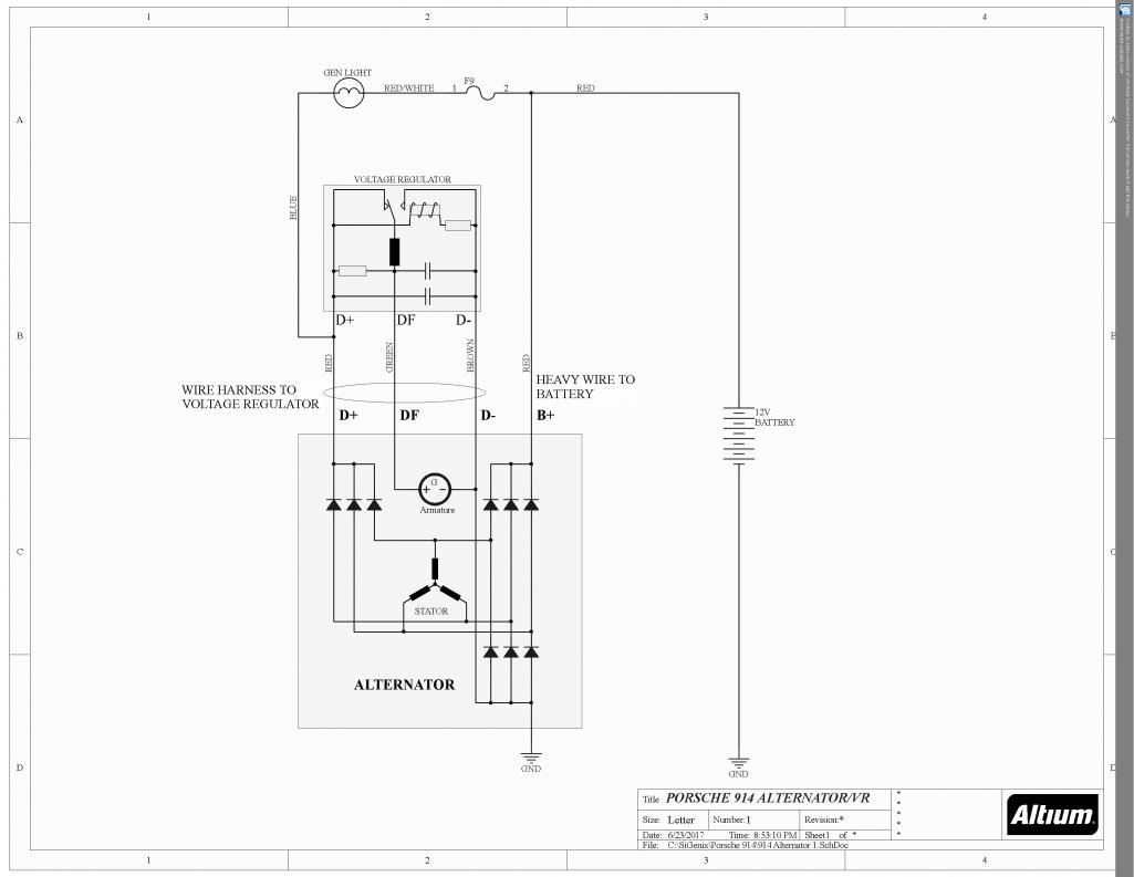
|
|
|
|
| ClayPerrine |
Jul 24 2020, 11:56 AM
Post
#25
|
|
Life's been good to me so far..... Group: Admin Posts: 15,503 Joined: 11-September 03 From: Hurst, TX. Member No.: 1,143 Region Association: NineFourteenerVille |
QUOTE(Spoke @ Jul 24 2020, 07:43 AM) Here's the simplified 914 charging circuit to go along with Clay's explanation. So, I sound like I really know what I am talking about?? (IMG:style_emoticons/default/biggrin.gif) |
|
|
|
| Mcraneiowa |
Jul 25 2020, 05:23 AM
Post
#26
|
|
Member Group: Members Posts: 82 Joined: 16-June 20 From: IA Member No.: 24,387 Region Association: None |
Fortunately the alternator and voltage regulator checked out fine. It appears the large red wire cover was brittle inside on the back of the alternator. Apparently when I got the engine running must’ve shaken enough that the wire ended up rubbing against one of the metal nuts on the back of the alternator.
Now that I’m moving forward with it, I’d like to get anybody thoughts or outcomes on building the your own wire harness for the alternator. Would there be any issues using a one gauge larger wire for both the three wire connections that go up to the voltage regulator and more importantly the red wire that leads back to the coil on the starter? If I use larger gauge wire for the three wires that lead up to the regulator I would likely use individual spade connections on each end instead of the three prong cover as I’m having a difficult time finding the type of spade connectors that will lock into the old cover harness plug. Just wanted to see if that would create any type of resistance or other issues. I will also put rubber backing on part of that air vent cover that attaches to the back of the alternator to prevent the nuts from making contact with the cover. I would likely have to either double up gaskets or more than likely just create a rubber seal to use between the alternator and rear alt cover. |
|
|
|
| Mcraneiowa |
Jul 25 2020, 05:43 AM
Post
#27
|
|
Member Group: Members Posts: 82 Joined: 16-June 20 From: IA Member No.: 24,387 Region Association: None |
QUOTE(ClayPerrine @ Jul 24 2020, 07:37 AM) QUOTE(Mcraneiowa @ Jul 24 2020, 06:49 AM) QUOTE(Mcraneiowa @ Jul 20 2020, 08:21 AM) OK so put the car up on jacks, removed the alternator (somewhat of a pain to do) and here’s where I’m at. It’s smoked the wiring in fact the large red lead wire inside the alternator air cover close to the nut was broke I half. Not sure if it was broken before I hooked it back up or that it burned it in half About an inch from the nut it screws on to I’m taking the original Bosch alternator and the new one and the wiring to a local alternator rebuild repair shop. I’ll get their opinion to see what happened so I don’t repeat the process.I’ll keep you posted what they tell me and if there’s a better solution Both new and old alternators checked out good. Voltage relay also checked out good. In addition I purchased a solid state voltage regulator. I am wanting to better understand and more importantly try to figure out how the wiring works since the old wiring burnt up so badly. I have four wires exiting the alt. The three that plug in (red, green, brown). They lead to voltage regulator and the big red wire that connects to starter solenoid. Do I have a simple understanding, that the big red wire handles created voltage from alternator back through stater which leads back to battery? Wouldn’t somehow that voltage need to be controlled by the smaller wires? What is the function of each of these wires as they are all pretty small gauge wires? Are one of the small wires of the three that lead to voltage regulator in essence telling the alternator to only send so much voltage back to the battery to prevent overcharging? Wouldn’t uncontrolled voltage have to run to the voltage regulator through one of these small wires and then VR would send signal through another wire back stating how much voltage to send back to battery. I just don’t really understand how it works and what those four wires do. Learning as I go. Here is how an alternator works, at least for a 914. The big heavy wire carries charging amperage to the starter post, and from there the battery cable carries it back to the battery positive post. The connection between the voltage regulator and the alternator is a little more complex. The brown wire connects the voltage regulator and alternator grounds together. The red wire sends alternator output voltage back to the voltage regulator to be measured. The "green" wire, which is actually light blue, is the wire that regulates everything. To explain the whole thing, I have to get into a little theory. Generators make voltage by passing a armature (moving coils of wire) past a permanent magnet. Spinning the armature passes the wires through the magnetic field of the permanent magnets and that makes DC voltage. Alternators work basically the same way,but there are no permanent magnets. They are replaced with the stator, and the rotor is powered to generate a magnetic field for the stator. The rotor consists of a coil of wire wrapped around an iron core. Current through the wire coil - called "field" current - produces a magnetic field around the core. The strength of the field current determines the strength of the magnetic field. The field current is D/C, or direct current. In other words, the current flows in one direction only, and is supplied to the wire coil by a set of brushes and slip rings. The magnetic field produced has, as any magnet, a north and a south pole. The rotor is driven by the alternator pulley, rotating as the engine runs, hence the name "rotor." Surrounding the rotor is another set of coils, three in number, called the stator. The stator is fixed to the shell of the alternator, and does not turn. As the rotor turns within the stator windings, the magnetic field of the rotor sweeps through the stator windings, producing an electrical current in the windings. Because of the rotation of the rotor, an alternating current is produced. As, for example, the north pole of the magnetic field approaches one of the stator windings, there is little coupling taking place, and a weak current is produced, As the rotation continues, the magnetic field moves to the center of the winding, where maximum coupling takes place, and the induced current is at its peak. As the rotation continues to the point that the magnetic field is leaving the stator winding, the induced current is small. By this time, the south pole is approaching the winding, producing a weak current in the opposite direction. As this continues, the current produced in each winding plotted against the angle of rotation of the rotor has the form shown in figure 2. The three stator windings are spaced inside the alternator 120 degrees apart, producing three separate sets, or "phases," of output voltages, spaced 120 degrees apart. A/C voltage is of little use in a D/C system, such as used in an automobile, so it has to be converted to D/C before it can be used. This conversion to D/C takes place in the bridge rectifier . Diodes have the property of allowing current to flow in only one direction, while blocking current flow in the other direction. Think of them as the electrical version of a check valve. The bridge rectifier consist of six diodes, one pair for each winding. One of the pair is for the negative half cycle, and the other for the positive half cycle. As a result of this diode rectification, the output of the alternator is not a pure D/C as one might expect, but a pulsating D/C. Because there are three windings, each with a positive and a negative half, by the time the voltage is passed through the diodes, there are six pulsations for each rotation of the rotor. This is close enough to D/C for most automotive components. Critical components, such as radios, have their own internal filtering circuits to further smooth out the waveform to a purer D/C. The regulator has two inputs and one output, and a ground wire. The inputs are the field current supply (the red wire) and the control voltage input (the blue wire), and the output is the field current to the rotor. The regulator uses the control voltage input to control the amount of field current input that is allow to pass through to the rotor winding. If the battery voltage drops, the regulator senses this, by means of the connection to the battery, and allows more of the field current input to reach the rotor, which increases the magnetic field strength, which ultimately increases the voltage output of the alternator. Conversely, if the battery voltage goes up, less field current goes through the rotor windings, and the output voltage is reduced. Field current supply is provided from two different sources - from the alternator itself, via the diode trio, and from the battery, via the generator lamp. When you first get in your 914 and turn the key on, the engine is not running and the alternator is not spinning. At this time, the voltage/current source for the field current is from the battery, through the ignition switch, and through the warning lamp. After the engine is started, and the alternator is up to speed, the output of the diode trio is fed back to the regulator, and serves as a source of current for the field current. At this time, the alternator is self sustaining, and the battery is no longer needed to power the automobiles electrical system. But don't ever disconnect the battery when the engine is running. It can damage things with voltage spikes! This brings us back full circle to the starting point - the generator lamp. When the key is turned on, current flows through the generator lamp, through the resisters, transistors, and field coil, and then to ground, causing the lamp to illuminate. Once the alternator is at full output, voltage from the diode trio equals the battery voltage. At this time, with 12 volts on both sides, the lamp is out. If the alternator should fail, voltage from the diode trio would drop, and once again the lamp would light from the battery voltage. If the alternator output is only a little low, the lamp will be dimly lit. If the alternator fails completely, and the output voltage goes to zero, the lamp will be lit at full brilliance. Conversely, if the battery should fail, and the battery voltage drops, with the output voltage of the alternator on one side and the low battery voltage on the other, the lamp will also light. As stated earlier, if the light grows dimmer as the engine is revved up, it is because the alternator voltage is rising with the RPM, producing more voltage on the alternator side of the lamp. The closer the output voltage gets to the battery voltage, the dimmer the bulb becomes. By the same way, if the light gets brighter with increasing RPM, it is because as the alternator voltage increases, it is getting higher than the battery voltage. The higher the voltage with respect to the battery voltage, the greater the voltage difference across the lamp, and the brighter it gets. Usually the differential voltage across the generator lamp is so small, you don't see the very dim light coming from the bulb. I hope that long winded explanation helps you to understand how the alternator works. Clay Clay, that was an excellent explanation. I was reading about alternators but still getting a little lost at various points along the way. Your walk-through step-by-step makes perfect sense. I took the alternator to a rebuilt shop in Des Moines the older gentleman checking it out mentioned as I was going to have to replace the wire harness anyway, I could simply build my own. He suggested using a one gauge larger wire because over time corrosion buildup creates resistance as was found in the large red wire that carries current back to the battery. Though not the cause of the failure as he was able to see where contact was made against one of the small nuts with the large red wire sat on the back of the alternator he said one size larger gauge wire would help against electrical resistance (also clean contacts). This got me thinking about the other three wires which I did mention adding on to my post in this forum. I’m thinking I could easily build this harness with the most important aspect would make sure to prevent any type of grounding not only in the back the alternator but as it runs through the engine tin. |
|
|
|
|
1 User(s) are reading this topic (1 Guests and 0 Anonymous Users)
0 Members:

|
Lo-Fi Version | Time is now: 3rd June 2024 - 01:25 AM |
Invision Power Board
v9.1.4 © 2024 IPS, Inc.