|
|
|
Porsche, and the Porsche crest are registered trademarks of Dr. Ing. h.c. F. Porsche AG.
This site is not affiliated with Porsche in any way. Its only purpose is to provide an online forum for car enthusiasts. All other trademarks are property of their respective owners. |
|
|

 Model Specific Information
914/4: 70 71 72 73 74 75 76 914/6: 70 71 72
  |

| StarBear |
 Jan 22 2021, 09:34 AM Jan 22 2021, 09:34 AM
Post
#21
|
|
Advanced Member  Group: Members Posts: 2,300 Joined: 2-September 09 From: NJ Member No.: 10,753 Region Association: North East States |
Ditto per @wonkipop; see my Virgo/Engineer evaluation note yesterday (1/21) at 12:51pm.
Started with @JeffBowlsby 's diagram which had the layout as he noted. Wonkipop got me to relook at my layout, which hadn't changed since I bought it at the dealer lot in May 1974 (that bowtie clamp SOOOO hard to remove, but sucked it up a few months ago to replace that hose finally). Suspect (?) that Porsche modified the system to this better arrangement for better collection/use of the collected vapors. Noted in the Emissions Control Systems image provided by wonkipop (original source). Isn't it amazing that after all these years, we're STILL finding/rediscovering new things about our little darlings? |
   |

 
|
| wonkipop |
Jan 22 2021, 11:04 AM
Post
#22
|
|
914 Guru Group: Members Posts: 5,517 Joined: 6-May 20 From: north antarctica Member No.: 24,231 Region Association: NineFourteenerVille |
of interest re evap emissions plumbing.
73 beetle. cannister is tucked up under the back guard in beetles. bottom of tank. fuel tank vapor line suction line to bottom of cartridge. pressure line to top of cartridge. fan provides pressure. throttle via aircleaner provides suction. same system, parts and principle as 914? both vw. 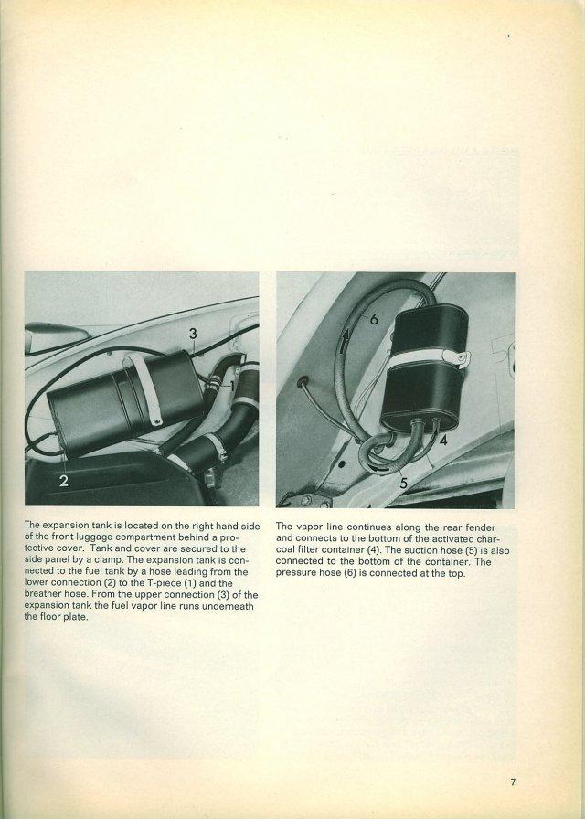 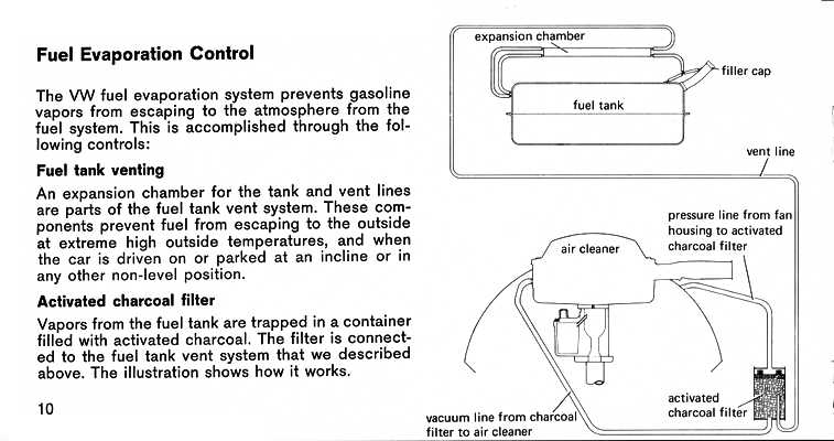 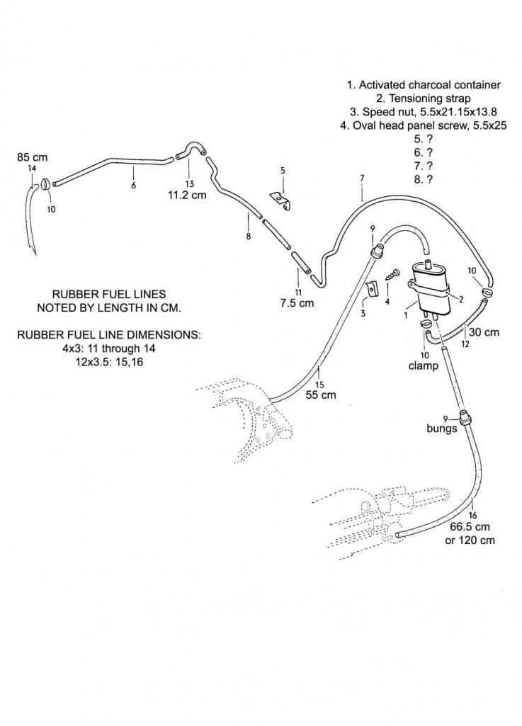 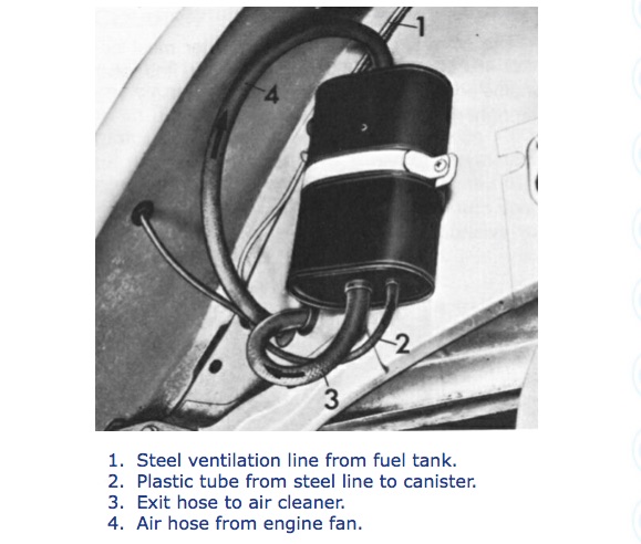 |
 |
|
| wonkipop |
Jan 22 2021, 11:21 AM
Post
#23
|
|
914 Guru Group: Members Posts: 5,517 Joined: 6-May 20 From: north antarctica Member No.: 24,231 Region Association: NineFourteenerVille |
researched this last year when replacing vacuum hoses.
first thought my car must have had wrong vacuum plumbing. checking out images of 1,8 L jet cars, realised if mine was wrong so were many others with identical plumbing arrangements right down to where the hoses were laid in the engine bay and under which other hoses. dug into misc vw technical literature/emis warranty that came with car. confirmed evap emis plumbing appeared correct in my car. (as per starbears car.) some images below show revised charcoal cartridge location next to battery with shortened pressure line. though cartridge position changes plumbing remains consistent with version that has cartridge on rear wall of engine bay (wonkipop/starbear cars). various 1.8 L engine bays. (images of wp car engine bay hoses in other thread). http://www.914world.com/bbs2/index.php?showtopic=351159 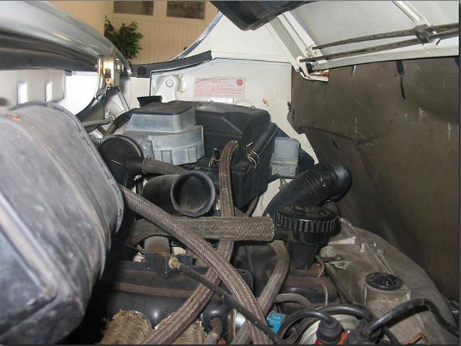 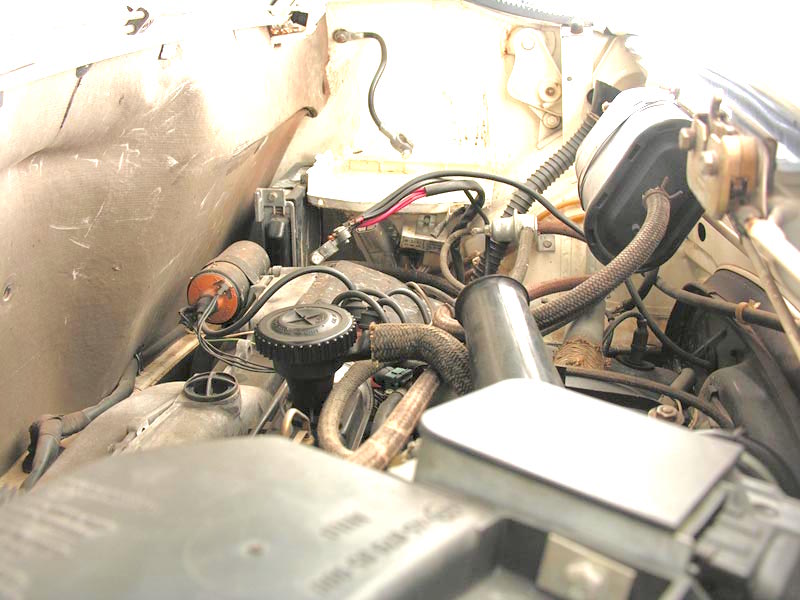 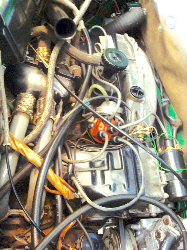 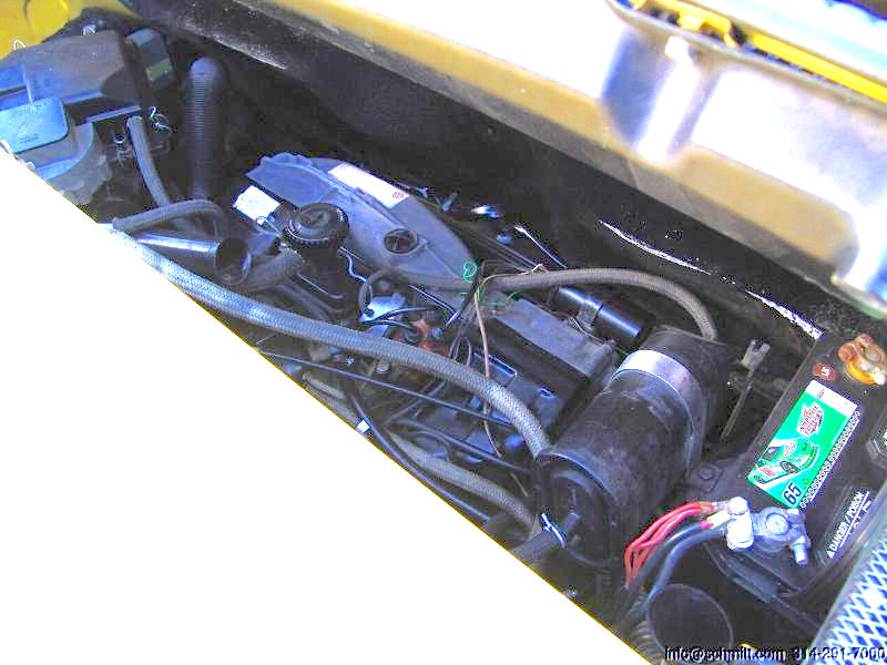 not to say that the plumbing is that way on earlier cars with the cartridge up front. have not had the opportunity to study one first hand down here. have some material on evap system for vw 412, ran L jet 1.8 like 74 914 1.8. i will try find where i filed it. given the history of mr. starbear's car and his ownership, its reason to think. by the way, that is amazing mr. sb that you have had the car since 74. |
|
|
|
| wonkipop |
Jan 22 2021, 12:35 PM
Post
#24
|
|
914 Guru Group: Members Posts: 5,517 Joined: 6-May 20 From: north antarctica Member No.: 24,231 Region Association: NineFourteenerVille |
re mr sb's thoughts on emissions engineering/workings of the cannister.
its a reasonable take. there are other explanations i have heard out there as well that make it trickier to really understand. most descriptions talk about the fan line pushing, or being a pressure line and the air cleaner line being a suction line. but i have also heard the fan line described as providing negative pressure. in which case the fan line (engine running) would be being used to suck fumes through the body of the charcoal the full length/depth of the charcoal from the smaller vapor line. while the suction line from the throttle would also be drawing it out to burn it. its possible the fan could be drawing air down the line as much as it could be pushing air, it just depends exactly where that line is tapped off the fan housing. i'm not really sure what the type 4 fan housing blower bleed line provides. however the interior of the cannister is interesting because usually the small vapor line extends well inside the cannister as a tube whereas the other lines connect more or less near the surface of the cannister. i am also aware that sometime during the mid 70s porsche reversed the hookup of the fan and aircleaner lines in 911s. they ran a similar kind of charcoal "passive" system in that model - though some variations might have had a switched mechanical valve in addition. but there is only so much you really want to know about these systems other than you have it correctly plumbed for the model/year you have? they are interesting in the sense that this simple device knocked out roughly 50% of the hydrocarbon emissions from cars in one move without affecting engine performance. what i am inclined to think is that the change was prompted by learning that if the charcoal became saturated due to too much urban driving and not enough long distance driving and purging then one or the other of these connecting hoses (fan bleed or aircleaner line) was the weak link that let fumes escape into the atmosphere. changing the configuration of the hoses might have given the charcoal greater capacity before the leak out occurred. in the vw system which the 914 has there is no mechanical valve. the charcoal is the valve. but.....i'm still just guessing because i do not fully understand it.... |
|
|
|
| wonkipop |
Jan 22 2021, 01:05 PM
Post
#25
|
|
914 Guru Group: Members Posts: 5,517 Joined: 6-May 20 From: north antarctica Member No.: 24,231 Region Association: NineFourteenerVille |
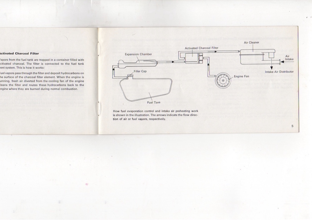
74 emmission warranty material.
    |
|
|
|
| StarBear |
Jan 22 2021, 02:34 PM
Post
#26
|
|
Advanced Member Group: Members Posts: 2,300 Joined: 2-September 09 From: NJ Member No.: 10,753 Region Association: North East States |
Wow; you da man @wonkipop ! So much to learn.....
|
|
|
|
| wonkipop |
Jan 22 2021, 04:04 PM
Post
#27
|
|
914 Guru Group: Members Posts: 5,517 Joined: 6-May 20 From: north antarctica Member No.: 24,231 Region Association: NineFourteenerVille |
i only know our cars starbear.
i don't know anything in detail about the earlier cars. i believe mr. b is correct in his assertion, but that applies to the earlier cars is what i think. i am as interested as mr. b in getting these technically right and mr. b has a wealth of information on his website and in his head. i've dug out more of my material that i had filed away from last year. i've now got a hunch about what goes on. 2 things. 1. VW has always been consistent in its plumbing and approach to the charcoal cannister. what is important to notice is that the cannister in all vws, beetles, kombis(buses) type 3s, 412s, things etc is always at the rear of the car with the engine. 2. porsche did do the cannisters plumbed the way mr. b says they are plumbed. i think the early 914s up to around the start of the 74 model is the porsche designed system that was in the 911s as well, that system is characterised by the cannister being in the front of the car near the gas tank. i think in the 74 914s, the 1.8s at least, when they shift the cannister to the engine bay they go over to the vw system. i will post some more material now from both vw and from porsche. these are technical manuals from vw which i think i got off the samba site a year ago when i was looking into this. the porsche diagrams i may have found on pelican parts forums and are from the factory manual, i dug these up a year ago too. |
|
|
|
| wonkipop |
Jan 22 2021, 04:16 PM
Post
#28
|
|
914 Guru Group: Members Posts: 5,517 Joined: 6-May 20 From: north antarctica Member No.: 24,231 Region Association: NineFourteenerVille |
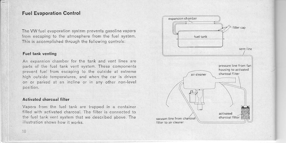
vw technical booklet, date 1970.
explains the evap system. consistent with 1974 914 1.8 plumbing.  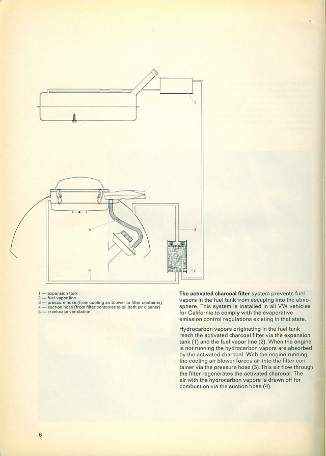 1975 VW emissions warranty type 1,2 5 years later. same.  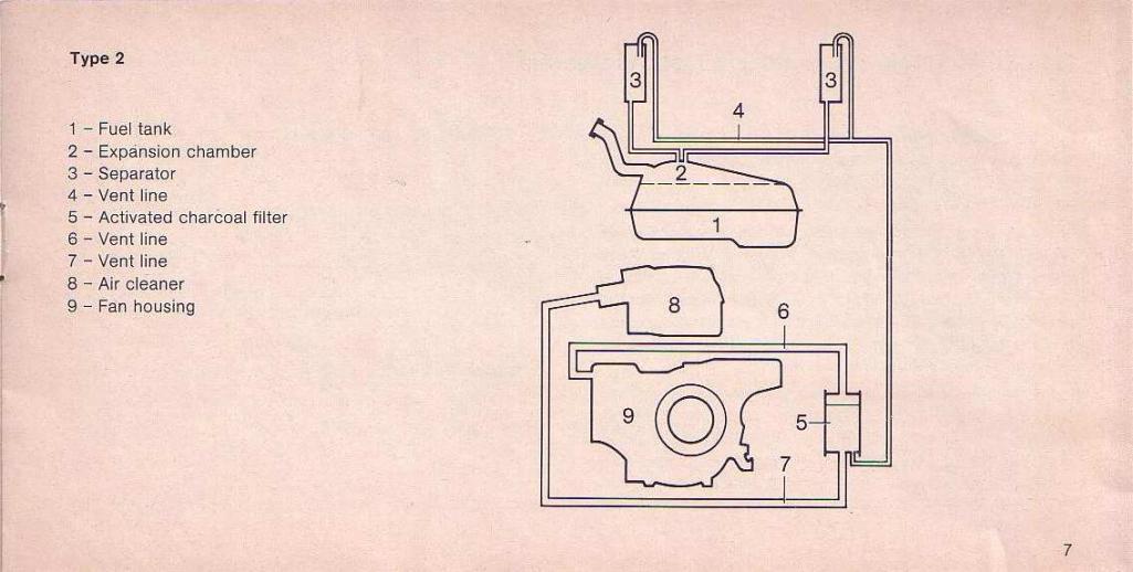 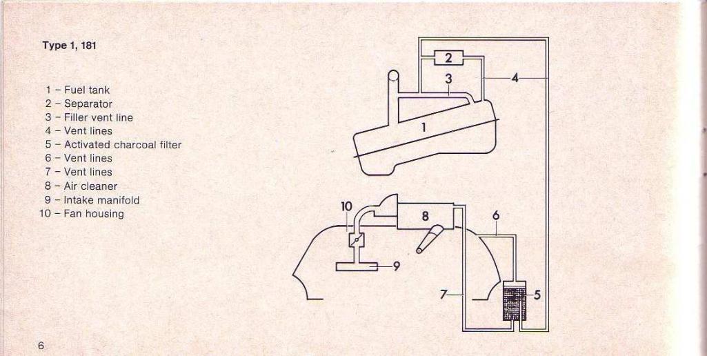 the 1973 emission warranty diagrams are the same as for 75 and same as tech booklet 1970, technical page for the kombi (bus) evap system. (note when looking at this the fuel vapor line is on the far side of the cannister and not visible, but its paired with the air cleaner line). 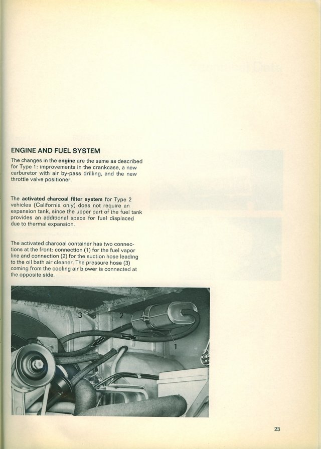 diagram for the type 2 kombi (bus) for 77 to 79. type 4 engine.  they are all consistent with plumbing arrangements etc for nearly a decade. they agree with the arrangement in the 74 914 1,8. |
|
|
|
| wonkipop |
Jan 22 2021, 04:24 PM
Post
#29
|
|
914 Guru Group: Members Posts: 5,517 Joined: 6-May 20 From: north antarctica Member No.: 24,231 Region Association: NineFourteenerVille |
but this one is interesting.
porsche evap emission system for the 911. 1970 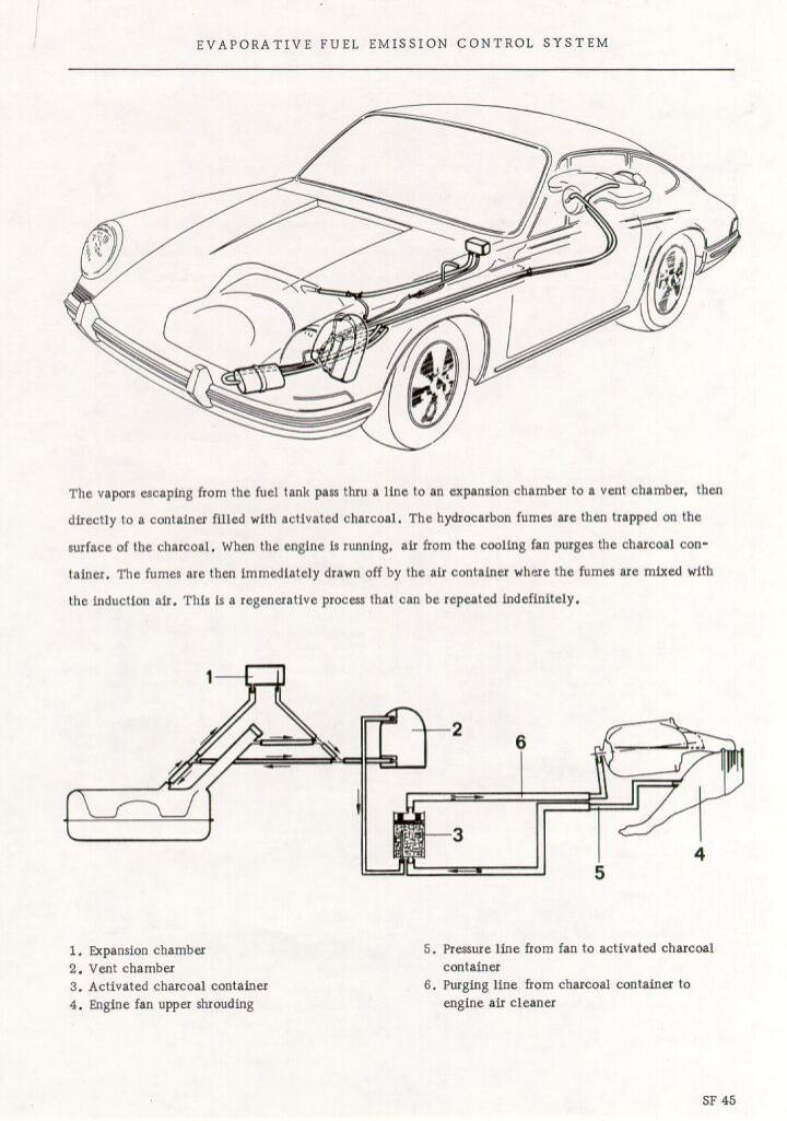 1974 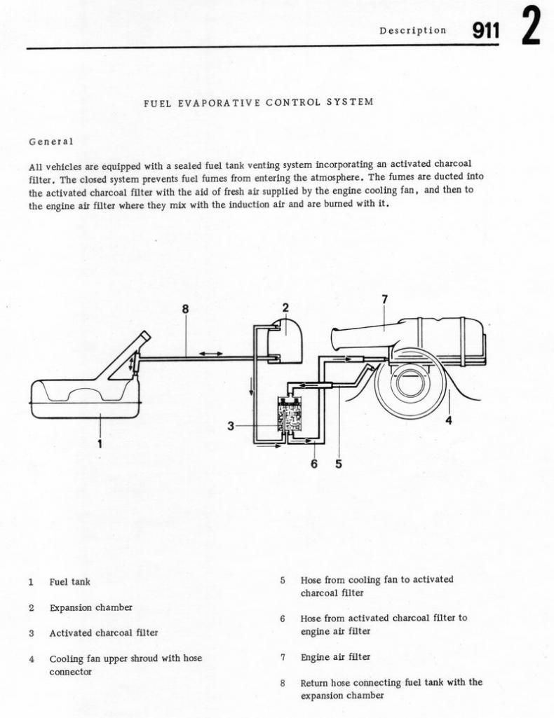 The 1970 911 porsche system agrees with mr. b's firm view that the 914 cannister is plumbed up opposite to the plumbing we find in our 74 914 1.8. The 1973 911 porsche system has been altered from its earlier 1970 design, now plumbed the opposite way and is in accord with the plumbing in the 74 porsche 914 1,8. I have no reason to doubt mr. b, i have never seen earlier cars in detail to know, but the schematics for the 911 support the idea that there was an earlier system and a later system. Secondly in contrast to porsche it appears that VW never revised their system, it stayed consistent. I think the cannister location has a bearing in the change of the plumbing, but i don't understand why as i don't have the physics/engineering training to know the behaviour of the two systems. |
|
|
|
| JeffBowlsby |
Jan 22 2021, 06:02 PM
Post
#30
|
|
914 Wiring Harnesses & Beekeeper Group: Members Posts: 9,255 Joined: 7-January 03 From: San Ramon CA Member No.: 104 Region Association: None |
w-pop, StarBear, I think you have made some interesting observations and I admire your research and efforts. After reviewing the posts, the 73 and 74 emissions manual diagrams, some photos I took of the plastic style charcoal canister in pieces, and my factory 914 parts book, I think there is a likely discrepancy, in the 1974 914 literature. Follow me:
Can we all agree that the functional purpose of the canister is to filter unburnt fuel vapor thru the charcoal matrix which then is transported to the intake for final burning rather than releasing the vapor to the atmosphere? If so we understand and agree on the operating principle. If so, then an air stream needs to transport that vapor through the matrix and then direct it to the engine intake air. The 73 diagram shows the parallel flow of air supply stream from the engine fan and vapor stream, but the diagram also depicts a long tube from the vapor supply line which deeply penetrates the matrix, and if this were so, the vapor would mostly bypass the matrix just before it exits the canister. I think that is an issue. The 74 diagram has the same charcoal canister diagram with the long tube but reverses the airflow. This seems logical. The vapor exits the long tube where it is deposited into the canister at the far end from where it enters the canister, then filters through the matrix carried by the airflow and exits through the canister end near where it entered. This seems plausible. Thinking there may have been separate 73 and 74+ canisters I checked my factory parts manual and there were only two canister PNs listed, the early metal sealed tyle and the later plastic serviceable type. Two and only two part numbers over the 914 production. I located the photos I took of an opened plastic canister. Note that there is no long vapor supply tube - vapors enter the canister near the end wall at a short stubby tube, not deep into the matrix. I don't recall and cannot tell from the photo what that smaller square white material is in the photos at that end, perhaps a filter fabric? If so it would retain charcoal dust from entering the engine if that end is also the airflow exit. At the opposite end a spring loaded air permeable plate compresses the charcoal and there is a filter fabric layer at that end. Functionally then, either end could be the airflow supply or exit end. But... If this end with both the vapor supply nipple and larger nipple is both the entrance and exit for airflow guided fuel vapors, because there is not the long fuel vapor tube as depicted in the diagrams, the the fuel vapor would not have have much exposure to the charcoal matric and hence only limited filtering effect. A short circuit as far as effective filtering goes. So, given the actual construction of the 914 plastic charcoal canister, I am inclined to continue to believe at this point, barring new evidence, that fuel vapor and air supply enter at the same end, and exit through the single port at the opposite end to the intake...like the 73 diagram and my diagram both indicate. What say you... Attached thumbnail(s) 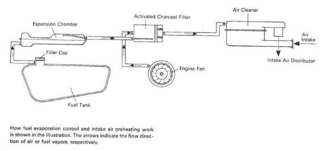 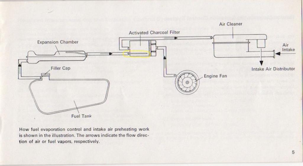 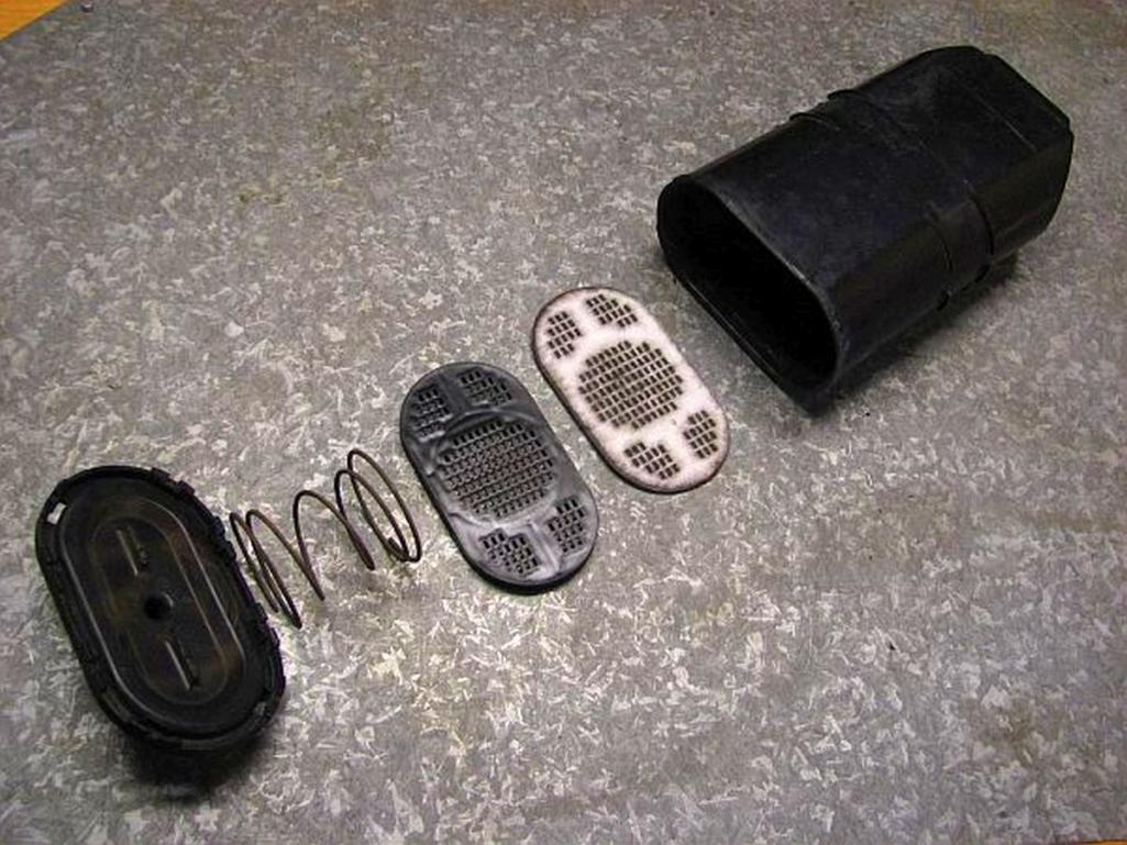 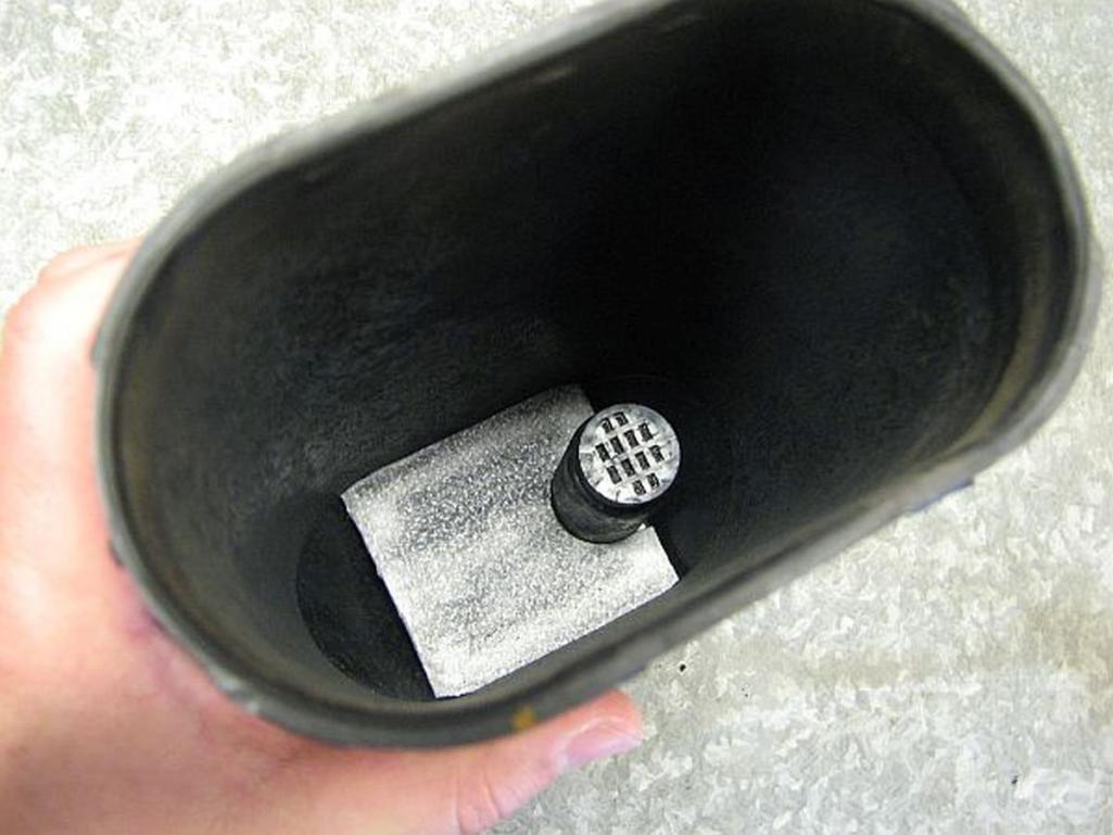 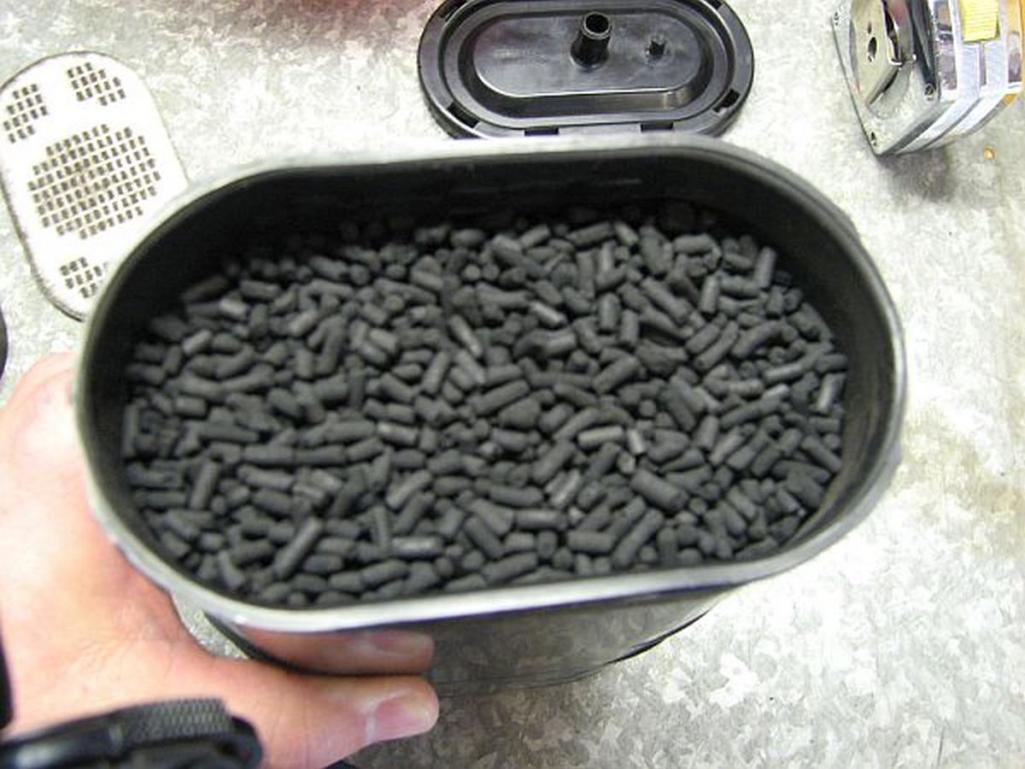
|
|
|
|
| wonkipop |
Jan 22 2021, 06:45 PM
Post
#31
|
|
914 Guru Group: Members Posts: 5,517 Joined: 6-May 20 From: north antarctica Member No.: 24,231 Region Association: NineFourteenerVille |
interesting mr. b.
i have a jan 74 build car. plastic cannister. and rear firewall mount. i don't know if that helps as i am not sure when plastic cannister kicks in. when it comes to the other lines of vw cars, they seem to plumb them the same, regardless of whether its earlier metal or later plastic from what i can tell. you have greater insight into the cannister itself, i've never seen inside one physically. just photos such as yours. i think your theory is probably pretty sound on how the airflow works. i'd have to think further about that and give it some thought. but..... the 1.8s are consistent with VW practice from 70 on with the introduction of the system. to discount the 1.8 plumbing would be to discount the plumbing arrangement on a vast no. of vws also produced during that time period and a decade of vw emissions tech literature? because they all work the way the 1.8 is plumbed. all of them. and they all have cannisters located near the engine bay. i think that is the key to understanding this. the shift to the engine bay. i don't think we have an answer yet. |
|
|
|
| StarBear |
Jan 23 2021, 09:26 AM
Post
#32
|
|
Advanced Member Group: Members Posts: 2,300 Joined: 2-September 09 From: NJ Member No.: 10,753 Region Association: North East States |
All; I opened my cannister a few months ago to refill the charcoal per the thread/video that had just been posted then. Easy!
IIRC, there was no long inner tube; just a short stub. Again, my Virgo/Engineer mindset provides two routes: 1) The specific arrangement doesn't really make much operational difference to the engine's running/performance - only emissions. So either way would work just fine as far as engine operation. With the long inner tube inside the cannister, the straight pass through design would make sense for the same reason as indicated below in 2). 2) I believe, being a former environmental air emissions engineer (one of MANY job paths during my working career), the purpose of the cannister was to capture the gas fumes as the tank was being filled (as JB noted), much like an industrial unit emissions absorber. So, the engine (hopefully!) wouldn't be running at the times of vapor entry and absorbtion into the cannister, with no airflow in the larger entry/exit hoses. Thus, vapors would tend to collect more so at the vapor entry point. The VW criss-cross hose design would make more sense, with air from the fan shroud pushing the vapors from the less-concentrated end of the cannister to the more-concentrated end so that those vapors wouldn't get absorbed unneccessarily onto the deeper charcoal nuggets. Industrial air filter design concepts for purging/evacuating absorbers. Meanwhile, I'll check with another 1.8 owner around here that I know to see what his configuration looks like. As always, thanks @jeffbowlsby for all you do to keep our heritage alive and cars running! SB |
|
|
|
| StarBear |
Jan 23 2021, 12:46 PM
Post
#33
|
|
Advanced Member Group: Members Posts: 2,300 Joined: 2-September 09 From: NJ Member No.: 10,753 Region Association: North East States |
@DCheek IRRC, you have a 1.8L 914 and an original owner?
How is your cannister hose layout? PS: Any plans for an All Air-Cooled Gathering this year? Summer may be too early, but maybe Fall? |
|
|
|
| wonkipop |
Jan 23 2021, 06:29 PM
Post
#34
|
|
914 Guru Group: Members Posts: 5,517 Joined: 6-May 20 From: north antarctica Member No.: 24,231 Region Association: NineFourteenerVille |
yes mr. sb. you can't find anything definitive in the factory manual regarding plumbing for the engine bay canister mount for the 74 1,8s on. only the emissions warranty schematic. i'm not inclined to think its a misprint. nor am i inclined to think the earlier pre 74 emissions warranty schematics are a misprint. or that the vw emissions schematics are misprints.
you can find hose layouts for vws, when it comes to factory workshop manual authority. as noted of interest there is definitive factory manual material on the 911 which demonstrates a change in the plumbing for the 74 model year. the change adopts the vw plumbing which is opposite to the earlier plumbing. they are responding to something. did their system fail in some way? it would not be the first time porsche engineering failed, they were not infallible. the earlier years of 914s have the porsche system matching the 911s. its a porsche design layout for location and plumbing, not a vw design layout. why? i'm less inclined to look for answers inside the can itself as mr. b does. not that it is wrong to do that. its just that i prefer to see the whole thing in the context of changing the location of the can as well. of interest to me is the question of pressure drops in lines, especially over length. i know about that in my line of work so i can see that the porsche long length system would have significant pressure drop - it would result in lower efficiency on the suction draw of the hose to the aircleaner and the ability of the can to purge during operation. ------------ re the primary function of the can - i dug up a paper a year back from the University of Colorado published 2003 which gave a detailed account of the history of emissions initiatives/legislation by US EPA. i know i am a kook to be interested in that stuff, guess thats why i have a 1.8. (IMG:style_emoticons/default/beer.gif) the heat soak phase of the engine after you switch it off having driven it and its effect on the fuel system of the car was found in the late 60s to cause the most dramatic release of hydrocarbon molecules. that phase lasts approx 1 hour after the engine is turned off. the charcoal cannister evap system universal to nearly all cars was designed with an emphasis on that. the other major vapor escape is during refuel as noted by mr. b when the new fuel displaces vapors that have formed in the tank. day to night expansion and contraction of the fuel is a gentler process and can almost be taken care of by condensation in the line from the tank to the cannister. the great thing about the system, coupled with the PCV system is single-handly the two things chopped hydrocarbon (big long chain molecules) emission from cars in half just like that. a beautiful piece of simple engineering. when it works. charcoal cannisters in most cars didn't have a fan feed like vw or porsche. the bonus of the ducted cooling fan? (IMG:style_emoticons/default/beer3.gif) they relied on a mechanical valve which opened the can to a passive fresh air feed line. the suction of the open throttle in the engine provided the draw from the can that pulled the stored fumes out and burned them in the engine. there was no positive pressure as such in those systems, just an air draw caused by suction from the engine itself. the main purpose of the fresh air line is to oxygenate the hydrocarbon molecules. that causes them to be released from the carbon (charcoal). they are not blown off the charcoal so much as flooded with oxygen. the design of the cans (as shown in mr. b's photos and in some even more detailed threads i came across in the samba site just now) supports the fan feed as an oxygen flooding device. the spring loaded end with the wide perforated filter creating a chamber would allow very efficient oxygen flow dispersal and flooding over the full width of the can. i believe that is why vw plumb the fan feed line into that end of the can. by having a kind of "supercharged" oxygen flow from the fan vw and later porsche were upping the ante on oxygen flooding? i think the idea might have been to be able to get a faster and more thorough purge of the can when the engine was running? as we all agree the weak point in the vw and porsche system is no valve. and in the case of the fan line no further filter and a direct route to the atmosphere once the fumes had saturated the charcoal. the fan line has an internal filter over the end of it, but its the same material that is at the other end too over the suction/aircleaner line. (the more universal types of cans in many cars prevented this because they had the mechanical valve as a final closure). the other line to the air cleaner at least has the aircleaner filter additional between it and the atmosphere (not that its 100% effective though, but it is there). and anyway that conforms to all the other manufacturers with the "unassisted" charcoal cans. they too have nothing final between the suction end of the can and the atmosphere but the engine air filter. what am i saying. mr. b's engineering logic on the workings of the can supports the vw system and the system on the engine canister L Jet 1.8s because the fan line is isolated by the most charcoal from the atmosphere. if the fan line was beside the stump fume inlet then it would be venting fairly easily and fairly quickly once the bottom few inches of the canister was saturated? you have to consider how the system works when the engine is not running because thats when the cannister is doing its job, in the one hour following engine shut down. there is no big air flow in that mode. its just fumes percolating in. and ultimately percolating out of the can once charcoal reaches absorption capacity. at that moment they percolate either straight out the fan hose or straight into the air cleaner hose - where there is one more seal, the air cleaner filter. the more charcoal there is absorbing between the fan hose line and the fume line the better. the shorter distance to the aircleaner line offers a quicker fume route sure, but its still effectively trapped inside the engine by the air cleaner filter and the design of the air cleaner housing. the hose is plugged into the top half of the aircleaner above the filter where they are likely to stay as vapor. fuel vapors tend to collect in the upper section of chambers rather than descend. what has to be kept in mind is that the engine is not running. its just fumes evaporating. when the engine is running the cannister is in purge mode, or should be. then you can talk airflows. and at that point it isn't about filtering fumes from the air its about burning them in the engine. if anything you want to pull them out of the cannister faster from the location where they are most concentrated. which as at the fume inlet end. this is my case for mr. b to consider. i'm saying the earlier system on the 914s and the 911s didn't work. thats why they got rid of it and changed to the engine bay mount in 914s and vw plumbing. as to why it may not have worked (as i am (IMG:style_emoticons/default/screwy.gif) and/or arrogantly saying?) , or why it was that porsche alone, at first, plumbed the other way, no one has really explained that fully - its taken that it worked and its authorative when looking at later cars - when it may not be. (IMG:style_emoticons/default/pray.gif) i would say, if it turned out it did not work over the 5 year/50,000 m period it was required to work, it was because of a combination of long lines and pressure drops and the adjacency of the fan feed line to the fume inlet line. it could be it was not discovered for a few years into the warranty period - because the charcoal does have a big capacity to absorb before it finally gets overwhelmed. it may have taken a couple of years for problems to emerge in cars. owners and dealers may have noticed fumes - who knows. but it did have a warranty on it so the EPA would have been taking notice in some capacity. the same history paper i read talked about how the EPA, particularly in california used to monitor the pollution systems in cars early on before more formal programs were introduced and their budget grew to the size it is today. they used to rent cars apparently and pull them into their workshop and examine them with a view to real world scrutiny. that would have been interesting. there was also it seems a more informal process they first applied when raising issues with manufacturers. only a few of the concerns and responses ever escalated to full scale legal fights between the EPA and manufacturers. chrysler is noted as a manufacturer who liked to get the lawyers out. back then (and maybe still?) porsche sold a ridiculous % of their output in california alone. if anyone would have jumped for the EPA it was porsche. probably would have even jumped at a shadow. -------- @ starbear - i like your description of the 1.8 as a "criss cross" plumbing system. the vapor feed line might play a part in that since having to get to the back of the car in the engine can system its just ran beside the fuel lines and enters the engine bay in the same place on the rhs. seems to set up the orientation of the can, as if they did not want to loop that line out and around in the engine bay but were happy to loop the others. |
|
|
|
| wonkipop |
Jan 23 2021, 11:50 PM
Post
#35
|
|
914 Guru Group: Members Posts: 5,517 Joined: 6-May 20 From: north antarctica Member No.: 24,231 Region Association: NineFourteenerVille |
QUOTE(StarBear @ Jan 23 2021, 12:46 PM)  @DCheek IRRC, you have a 1.8L 914 and an original owner? How is your cannister hose layout? PS: Any plans for an All Air-Cooled Gathering this year? Summer may be too early, but maybe Fall? Dr. 914 has a 74 1.8 with an engine bay can. description says its a 10k miler. has images in his website gallery. looks pretty unmolested to me. (do i even see one faded red hose ----???) if so i have a question about that, as i had one in same spot, that came off, that i cannot decide was it red, was it brown, was it just discoloured, still have it in bag - was just the one hose. off the "decal" valve. someone should ask him whats going on with the can hoses? his photos seem to point to SB and W layouts. need clearer angles as i lose track of the air cleaner hose. but i can see the fan hose doing the s curve to the lhs of the can. 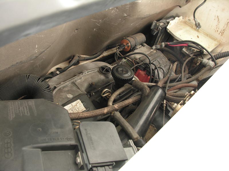 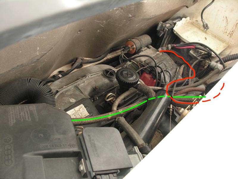 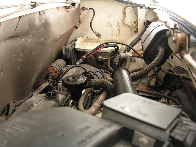  |
|
|
|
| wonkipop |
Jan 24 2021, 12:50 AM
Post
#36
|
|
914 Guru Group: Members Posts: 5,517 Joined: 6-May 20 From: north antarctica Member No.: 24,231 Region Association: NineFourteenerVille |
a reasonably reputable 75 1.8 example.
would say 99.9% trustworthy? but you never know. the extra hose to the rhs heater outlet from the heater fan is a bit of a question mark. as far as i know its one hose only to lhs. so its had a mod? and the long hose isn't a factory hose. nor is the coil original. https://rmsothebys.com/en/auctions/mo17/mon...e-914-18/430426 same plumbing as SB and W cars, though can is in final position next to battery. 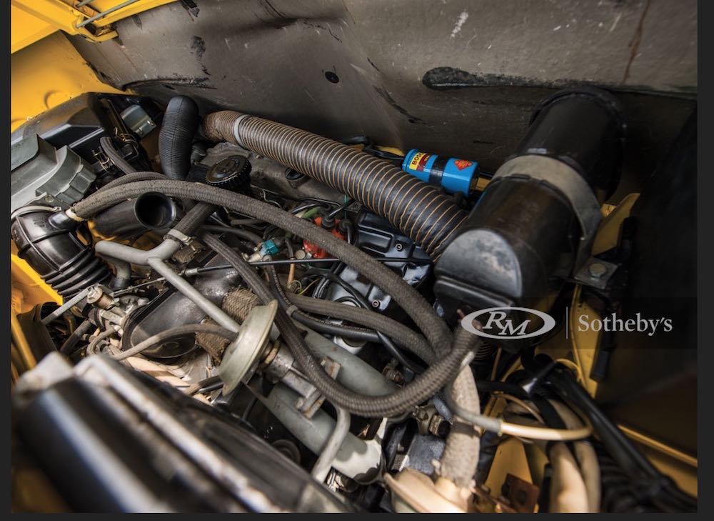 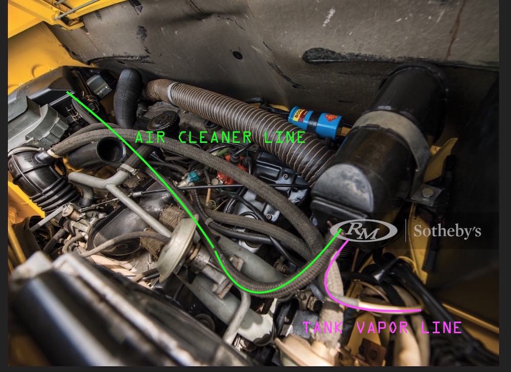 something changes in the 74 model year. not saying it changed on the 2.0 L cars, i just don't know how they plumb up in the engine bay to the can. don't have one - don't have an opinion on those. |
|
|
|
| StarBear |
Jan 24 2021, 09:11 AM
Post
#37
|
|
Advanced Member Group: Members Posts: 2,300 Joined: 2-September 09 From: NJ Member No.: 10,753 Region Association: North East States |
@wonkipop - You could write a research paper, for sure! (IMG:style_emoticons/default/pray.gif)
Concur with your assessment of our perhaps (?) overindulgence with this topic, but as you say, we're 914 owners so a) it can be expected and b) folks give us wide berth for suchness. (IMG:style_emoticons/default/wacko.gif) Will check with Dr. 914. |
|
|
|
| StarBear |
Jan 24 2021, 09:17 AM
Post
#38
|
|
Advanced Member Group: Members Posts: 2,300 Joined: 2-September 09 From: NJ Member No.: 10,753 Region Association: North East States |
@dr914 @autoatlanta.com
George - might you have any insight/hose layouts per the above thread for 1974 1.8Ls (and presumably 2.0L)? The posted diagrams indicate one layout and our unmodified vehicles, and the Emissions Control Systems Warranty Manual, show another. Thanks! |
|
|
|
| StarBear |
Jan 24 2021, 09:49 AM
Post
#39
|
|
Advanced Member Group: Members Posts: 2,300 Joined: 2-September 09 From: NJ Member No.: 10,753 Region Association: North East States |
Another hose layout - presumably (?) a 74 1.8L with the charcoal cannister in the front; from a current posting on the PCA Mart.
Presuming the bumpers have been back-dated; the rest of the car (engine layout, interior) look like a 74. Maybe (???) VERY, VERY early 74??. (IMG:style_emoticons/default/blink.gif) Attached image(s) 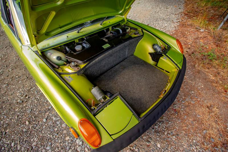
|
|
|
|
| wonkipop |
Jan 24 2021, 02:23 PM
Post
#40
|
|
914 Guru Group: Members Posts: 5,517 Joined: 6-May 20 From: north antarctica Member No.: 24,231 Region Association: NineFourteenerVille |
Evolution of the porsche evap system 1969-78 for 911 models
source/thanks to pelican parts forum. 1. 69-73 the fan hose plugs in next to the fume hose and is opposite the suction hose. the can is located in the front trunk adjacent to the fuel tank. 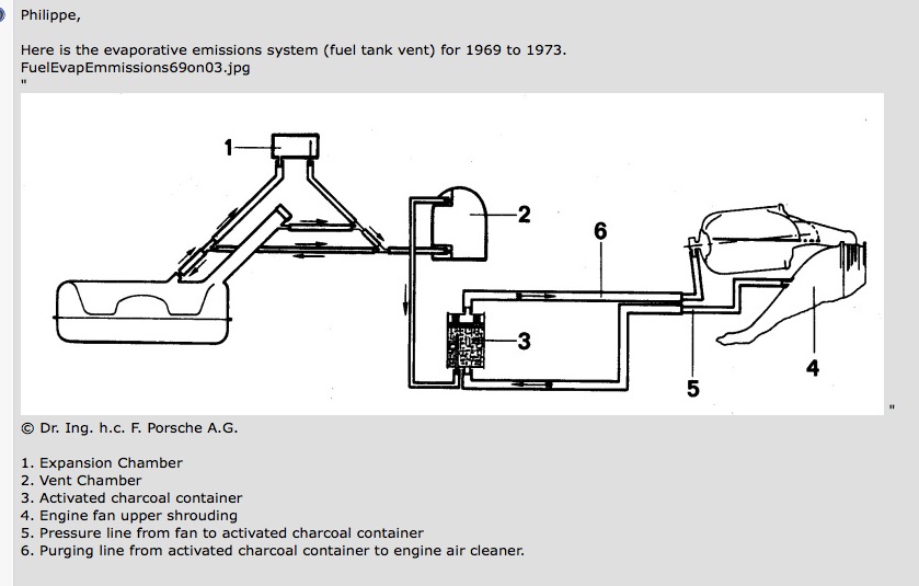 2. 74-77 the suction hose plugs in next to the fume hose and is opposite the fan hose. the can is moved to inside the rear fender well close to the engine bay. pretty much identical to its location in a beetle from 1970 on. 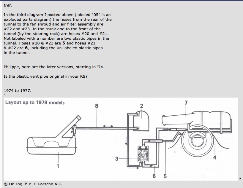 3. 78 the fan hose is deleted from the system. 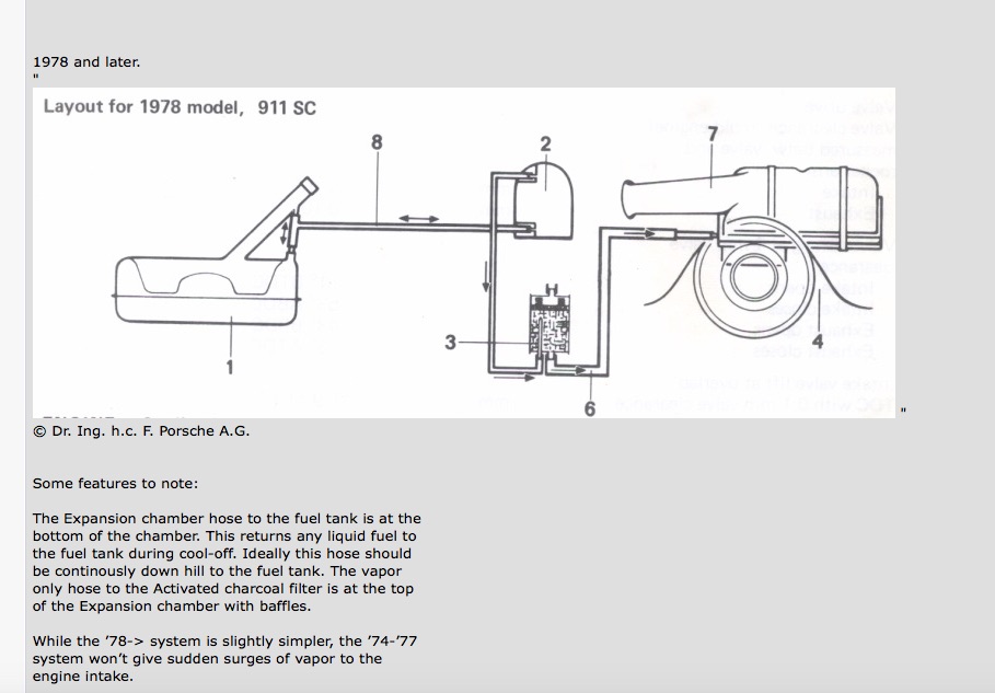 porsche altered its design for the evap system for the 74 model year and again for the 78 model year for the 911 models. from 74-77 porsche run a system at the can identical to the vw system commenced 1970 right down to revising mounting the can directly adjacent to the engine bay in the rear of the car. as far as i know porsche and vw used identical cans. at least look so on outside. mr. b is correct for 70-73 models plumbing. (the can is in the front trunk of the car). mr. sb is correct for 74-76 models, 1.8 at a minimum, plumbing. (the can is in the engine bay). @ mr sb. - topic has probably died on the operating table - but you are correct to raise the question of the early 74s with the can in the front boot (trunk). is that plumbed as per 70-73? i'll leave that to someone with one. given myself enough of a headache. |
|
|
|
|
1 User(s) are reading this topic (1 Guests and 0 Anonymous Users)
0 Members:

|
Lo-Fi Version | Time is now: 26th May 2026 - 07:28 AM |
Invision Power Board
v9.1.4 © 2026 IPS, Inc.