|
|
|
Porsche, and the Porsche crest are registered trademarks of Dr. Ing. h.c. F. Porsche AG.
This site is not affiliated with Porsche in any way. Its only purpose is to provide an online forum for car enthusiasts. All other trademarks are property of their respective owners. |
|
|

 Model Specific Information
914/4: 70 71 72 73 74 75 76 914/6: 70 71 72
  |

| wonkipop |
 Dec 10 2020, 07:37 PM Dec 10 2020, 07:37 PM
Post
#1
|
|
914 Guru  Group: Members Posts: 5,581 Joined: 6-May 20 From: north antarctica Member No.: 24,231 Region Association: NineFourteenerVille |
think this is the right section of the website to put this in.
even though its a spanner job, the material is historic and possibly of esoteric industrial archeology interest. who knows? 1. background. i recently recommissioned my 74 1.8 after nearly 16 years of storage. i paid for storing but i always knew i would. complete rebuild of fuel system. we got the original fuel pump to come to life but it bled from every orifice. flow rate was ok however and motor still worked fine - just a minor fire hazard. 2. action. to get the car up and running we took out the original 0 580 463 009 fuel pump and re-plumbed for a modern two port in line pump. car runs. having done that, in some ways i felt the plumbing was a little compromised over the original given the pump needed to be repositioned to have a line in the back as well as out the front making the line out a pretty tight turn to get up into the engine bay. but it runs. 3. delayed dream due to thoughts of it being a nightmare. in the back of my mind was the idea of rebuilding the original fuel pump. general consensus down here at the bottom of the world (aus) was don't bother, its a sealed unit and unserviceable. 4. then. a young guy with a 1970 citroen DS21 IE inspired me. he had taken his similar bosch 3 port pump apart and rebuilt it proving its possible if you are determined enough. i think the pump in the citroen was a 0 580 463 005, which the 009 replaced not sure when the 009 came in, but its before the 010 (which is the completely different pump and fitted to the later 75 and 76 cars - amongst the first of the in line 2 port types). maybe the historians know exactly when 009 kicked in, i'm guessing it comes in with the L jetronic in 74 model year, but it could be earlier. externally a 005 is indistinguishable from a 009. i might have discovered the difference internally in what i have taken apart to date. TAKING the 0 580 463 009 apart. STEP 1. undo the 4 screws securing the pump and outlet housing on top of the unit. keep it all upright and vertical. remove the top part of the housing. remove the upper o-ring. remove the metal pump vane and the five cylindrical magnets housed in it. (bag them so you don't lose them - they seem to be weakly magnetic cylinders). remove the vane housing. remove the lower o-ring. If your pump is only leaking from this upper housing its an easy fix. just replace the two o-rings and put it all back together. Don't need to post pics of this stuff its very simple to do. the o-rings are 30x2mm i believe. could be 31x2mm. yet to confirm. still to make the trip to the specialist o-ring shop here in melb aus. i'll be looking to find the best fuel resistant o-rings i can get hold of. suprisingly these o-rings were still in good shape in my pump and were not the source of the leaks. but i will be replacing them. |
   |

 
|
| wonkipop |
Dec 10 2020, 07:52 PM
Post
#2
|
|
914 Guru Group: Members Posts: 5,581 Joined: 6-May 20 From: north antarctica Member No.: 24,231 Region Association: NineFourteenerVille |
STEP 2.
Going further in. The next job is to get the cylindrical motor housing off the lower part of the pump and port housing. Its crimped on. Its made of thick metal. You need to go at it carefully and patiently. You do not want to over distort it working the crimping loose. A little further down below where the crimps are there is located another o-ring seal internally that seals the motor housing to the port housing. I used three tools. A very small pair of mult-grips. a small 7mm open ended spanner and a screwdriver i could fit into the slots on the upper port housing that engages with the crimping on the motor housing. After i had the crimping opened up enough i used a chisel and a nylon headed hammer to work the upper housing out of the lower housing. to avoid distorting the lower housing i refitted the mounting clamp for the fuel pump to the housing and then clamped the feet of the mounting clamp in a vice. i did all this very tentatively but i got it apart. it took me a couple of hours of delicate (possibly overly delicate) work. but it was the first time i had done this. You have to be careful not to distort the motor housing down further where the o-ring seal locates internally. in photo you can see groove where o-ring sits. its ok to distort the very upper area of the housing getting the crimps out so long as you don't cause it to go out of round down where the seal is. when you pull the motor out of the housing there will be some shims that fall off the end of the motor axle. these will probably be stuck to the internal magnets in the housing. collect them up and bag them. there were four in this motor. don't lose them. 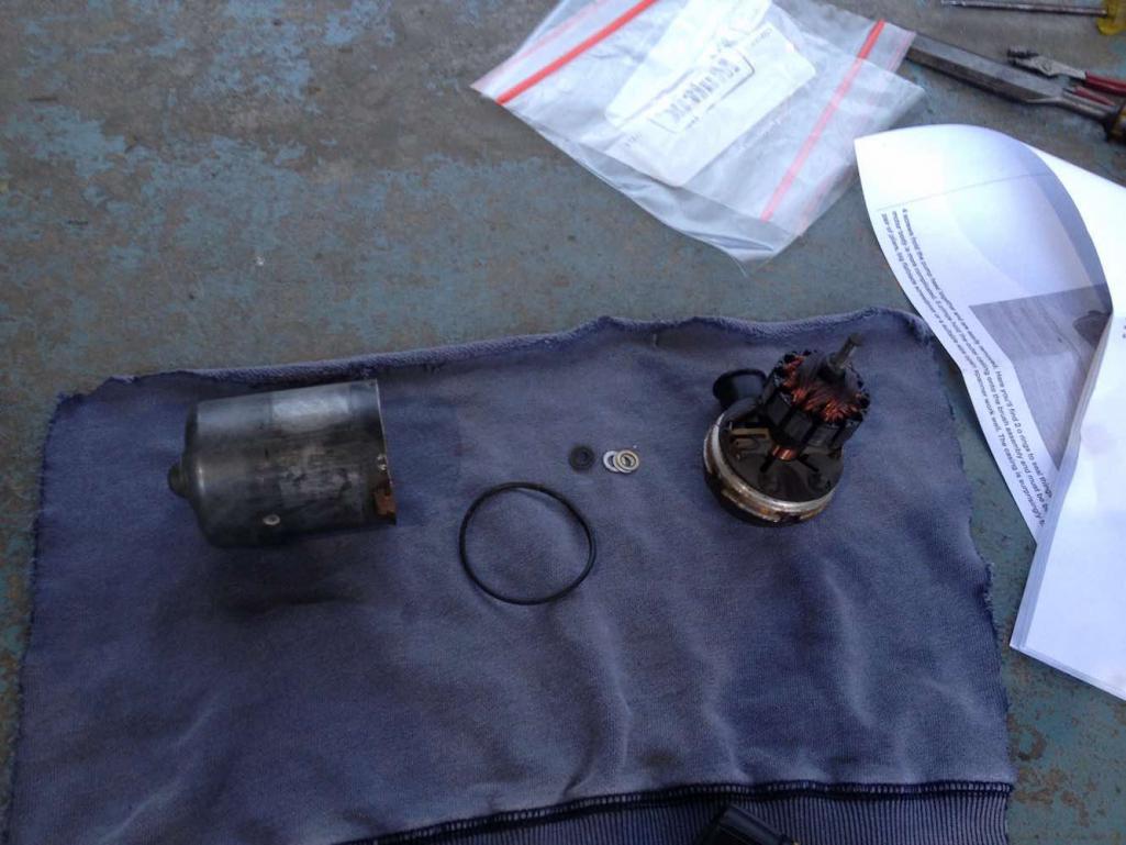 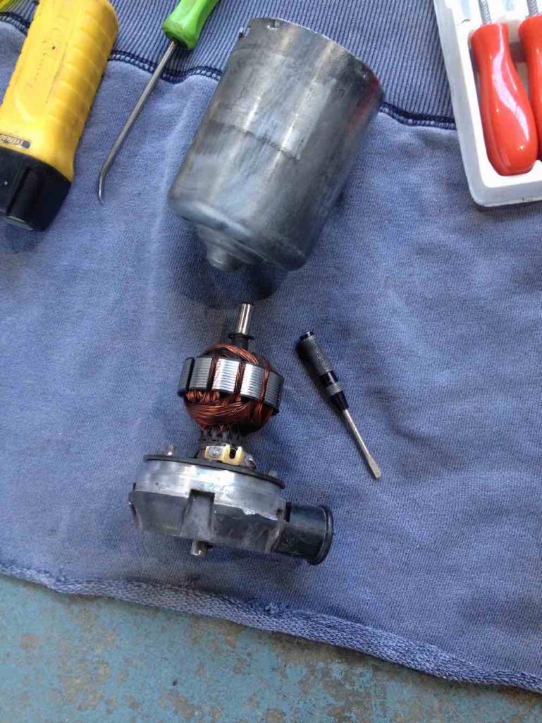 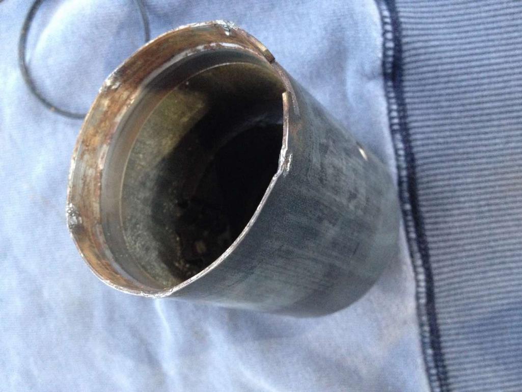 |
|
|
|
| wonkipop |
Dec 10 2020, 08:07 PM
Post
#3
|
|
914 Guru Group: Members Posts: 5,581 Joined: 6-May 20 From: north antarctica Member No.: 24,231 Region Association: NineFourteenerVille |
STEP 3.
step 2 gets you to one of the internal leak failures. the big o-ring sealing the motor housing. i inspected this o-ring. it was hard on one side and had definitely been leaking. but there is one more seal to go. the electrical plug. Additionally at this point you can inspect the commutator and brushes on the electric motor. Mine were in good condition with reasonable level of wear. made sense. the car is a two owner car with 44 K miles and its been dormant for the last 16 years. the pump is worth saving assuming i can solve the leaks with new seals. Moving on. Electrical plug removal. at this point you have to get the lower part of the port/pump housing apart and detach the motor. first. there are two electrical connections rising from the plug to the brush holders. these wires are like springs at the brush ends. take a soldering iron and release the solder joints so they are free. next there are three spring washers which hold the pump/port housing together. work these off with a fine pick and a small fine screwdriver. finally drive out a very small pin which secures the motor axle to the top of the pump housing. you will need an ultra small pin punch, less than 2mm. or 1/16 in imperial size. be careful driving the pin out. i secured the axle in a vice with soft jaws and placed a rag below the vice to catch the pin. you do not want to lose this pin, its very very small. pull the motor out of the pump/port housing. carefully lift the internal face of the pump/port housing up threading the spring wires through it as you go. once apart stop there. you will be looking at the back of the electrical plug and if its a 009 pump it should look like the last image. there will be an earth wire, going to a stamped pin and the same stamped pin holds the sprung wire that connects to the brush holder on the motor section you have detached. to note. a 005 may not look like this. at some point i will know as i have a 005 to disassemble, but i have not done that yet. 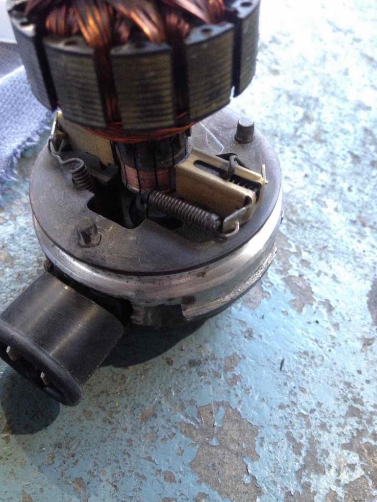 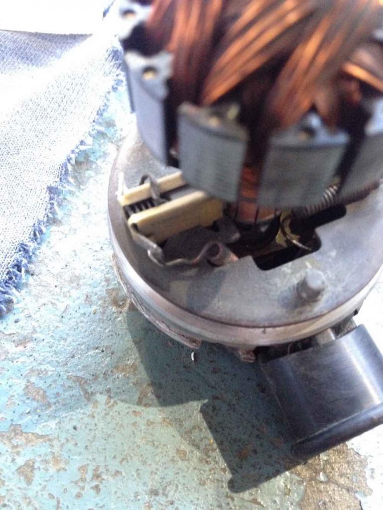 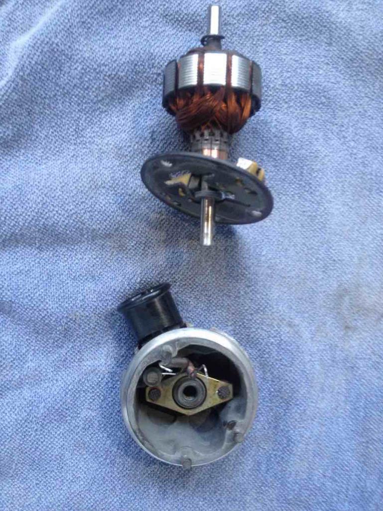 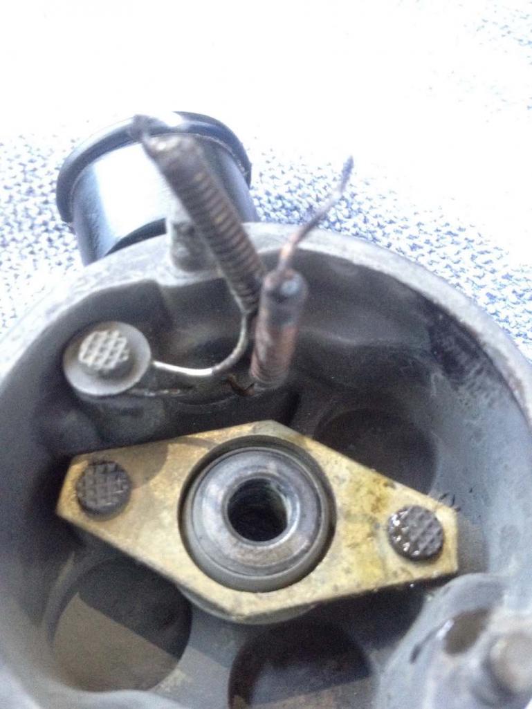 |
|
|
|
| wonkipop |
Dec 10 2020, 08:15 PM
Post
#4
|
|
914 Guru Group: Members Posts: 5,581 Joined: 6-May 20 From: north antarctica Member No.: 24,231 Region Association: NineFourteenerVille |
STEP 4.
snip the earth wire to the plug. as close as you can to where it is connected to the stamped clamp. you can resolder this later to reconnect it. carefully ease out the electrical socket. lots of wiggling and gentle coaxing. it will be gummed on and take a bit to get it to release but you don't want to tear it out with force or you risk breaking off the two electrical connections at their base. if that happens things can get harder to repair. look for the o-ring. in my case there was not much left of it. this was the source of the main leak. collect all the o-rings up. the 0-ring for the motor casing is likely a 51x2.5mm and the electrical connection is a 7.8x1.9mm i think, but it was squashed very flat, so i may experiment with this by getting a couple of different sizes to get the correct final fit. This is where i have gotten to until i obtain all the o-rings. more when i begin reassembly next week or two. 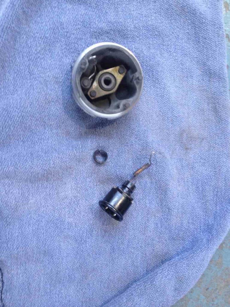 |
|
|
|
| wonkipop |
Dec 10 2020, 08:39 PM
Post
#5
|
|
914 Guru Group: Members Posts: 5,581 Joined: 6-May 20 From: north antarctica Member No.: 24,231 Region Association: NineFourteenerVille |
POST SCRIPT.
there are a couple of similar 3 port fuel pumps lying around in the workshop which have been thrown at me to investigate, given i got the 009 apart. one is a 005 that was taken out of a 1974 SAAB EMS. externally it looks mint. I'm not sure where these were located on a SAAB but must have been a protected position. the pump has been tested and it is below flow specs at 700ML per minute. (for a 914 the flow rate is 50L/hr or 833ML/minute). the other is a similar type of bosch unit that came out of mercedes 600 series. It took me a day to take the 009 apart, but i took my time and thought about how to do it. It took me less than two hours to get the mercedes unit apart to almost the same level of disassembly, felt confident with the method - though the mercedes unit was a lot more unwilling to ease the outer casing shield apart from the upper port casting. it was in their tight. It was interesting once you got inside it. the motor has what i would call turbulence shrouds top and bottom. white plastic shrouds. these encase the coil windings armature section of the motor. I have seen images of the interior of the citroen fitted pump and the motor had only a top shroud not a bottom shroud. I'm not sure if the citroen unit was a 005 pump but i think it might be. I have yet to take apart the 005 pump that came out of the SAAB so that might be interesting to see if it has a turbulence shroud, either completely like the mercedes or a half unit like the citroen. The citroen ran D-Jet fuel injection. the mercedes pump has a different arrangement in terms of its pump head, ports and o-rings than the 009/005 units fitted to the 914s. so its not an exact comparison - but i believe early VW bosch fuel pumps for EFI have the fully shrouded armarture similar to the mercedes unit. in pulling the mercedes pump apart we found the reason for the failure. the electric motor commutator had worn to such an extent a portion had broken off and jammed against one of the brushes preventing the motor from rotating. we might try and get the commutator and brushes rebuilt/renewed if we can find someone who can do it for a reasonable cost. you can still get these pumps new from mercedes but at horrendous cost. so its kind of worth having a go at rebuilding them. anyone rebuilding a 005/009 fuel pump from a high mileage 914 will likely find similar advanced wear of the commutator and brushes and would need to rebuild those parts if they wanted to renew the units. once i get the SAAB one apart I'll post some images. 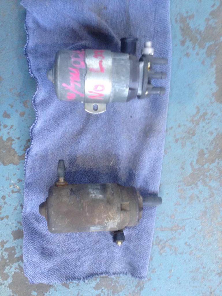 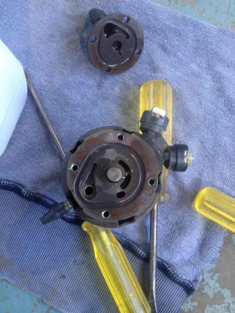 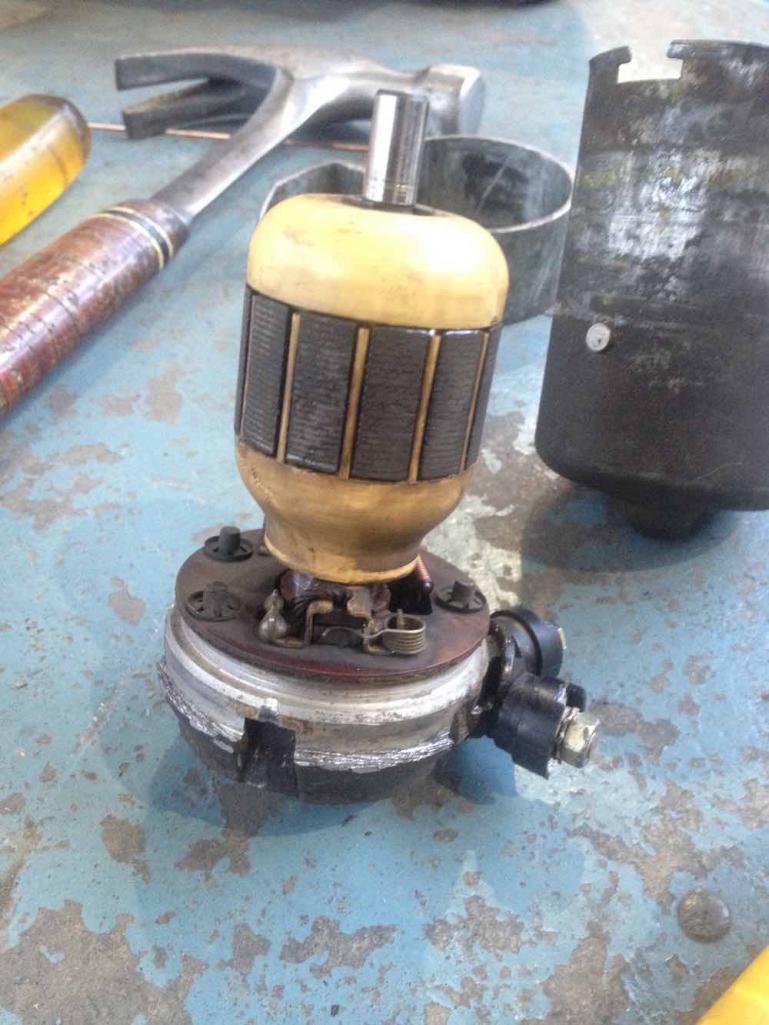 |
|
|
|
| SirAndy |
Dec 11 2020, 11:55 AM
Post
#6
|
|
Resident German Group: Admin Posts: 42,486 Joined: 21-January 03 From: Oakland, Kalifornia Member No.: 179 Region Association: Northern California |
(IMG:style_emoticons/default/smilie_pokal.gif)
Very nice writeup, i'm going to link that in the classics! (IMG:style_emoticons/default/beerchug.gif) |
|
|
|
| wonkipop |
Dec 13 2020, 07:26 PM
Post
#7
|
|
914 Guru Group: Members Posts: 5,581 Joined: 6-May 20 From: north antarctica Member No.: 24,231 Region Association: NineFourteenerVille |
Update - O Ring sizes.
Sizes quoted above were given by the guy with D Jet Citroen for 005 pump. He seemed to give sizes to internal diam and to round numbers. here are British Standard O-Ring sizes after visit to the O-Ring suppliers. (southern bearings in melbourne aust, supply to the mining industry). electrical connection plug. BS 011 thickness 1.78mm OD 11.21mm (1) - EDITED TO CORRECT O RING SIZE. pump casing internal o-ring BS 135 thickness 2.62mm OD 54.14mm (1) top casing and port housing. BS 027 thickness 1.78mm OD 35.03mm (2) - EDITED TO CORRECT O-RING SIZE. port housing pressure relief valve - SIZE TP BE CONFIRMED (1) Grade/material VITON. You really just want VITON for all O Rings in the pump. at a pinch you could use NITRILE for the port housing o rings as these are much easier to replace if they give trouble. |
|
|
|
| wonkipop |
Dec 16 2020, 12:34 PM
Post
#8
|
|
914 Guru Group: Members Posts: 5,581 Joined: 6-May 20 From: north antarctica Member No.: 24,231 Region Association: NineFourteenerVille |
005 Pump.
Disassembled the 005 pump today. Getting better, all apart in about an hour. The top part of the pump is identical to the 009 unit. The motor itself is where the differences are. The armature section (electro magnets) and interior permanent magnets (Fixed to the pump casing) matches the dimensions of the older and earlier mercedes fitted unit but lacks any "turbulence" shrouds (if that is what the shrouds are). In the 009 unit that supersedes it the armature section has smaller sized electromagnets. The plate holding the brushes and spring wires connecting to the electrical plug is closer to the earlier mercedes fitted unit in layout and components. Basically the internal components are being miniaturised and reduced in size from 005 to 009. I haven't measured all the different components but the external casing of the 009 looks slightly shorter in length than the earlier 005. The reason that the 005 has come apart is that it was delivering insufficient flow when tested. at first glance visual inspection we can't seem to find any obvious reason for that. the motor and internals are in the same condition (very good) as the 009 pump that came out of my 914. The 1974 SAAB EMS it was fitted to had done approx 80,000km (50,000 m). The pump came out of the SAAB years (decades) ago and has been stored since. Comparison images. 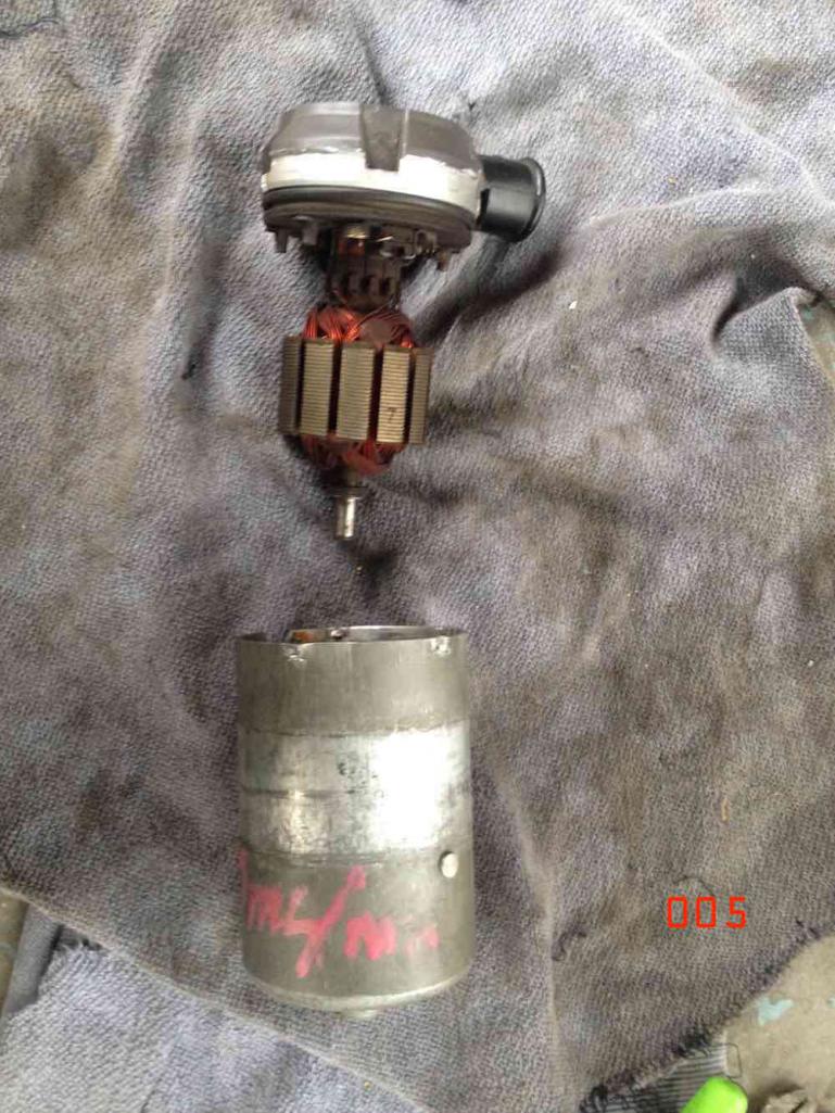 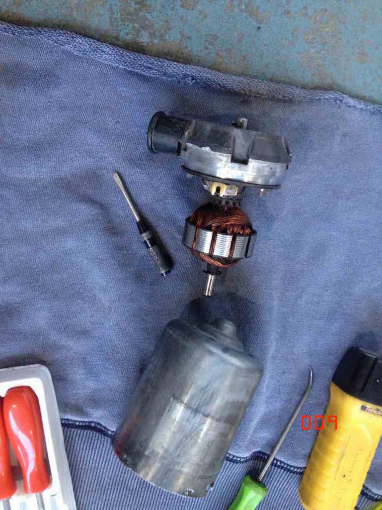 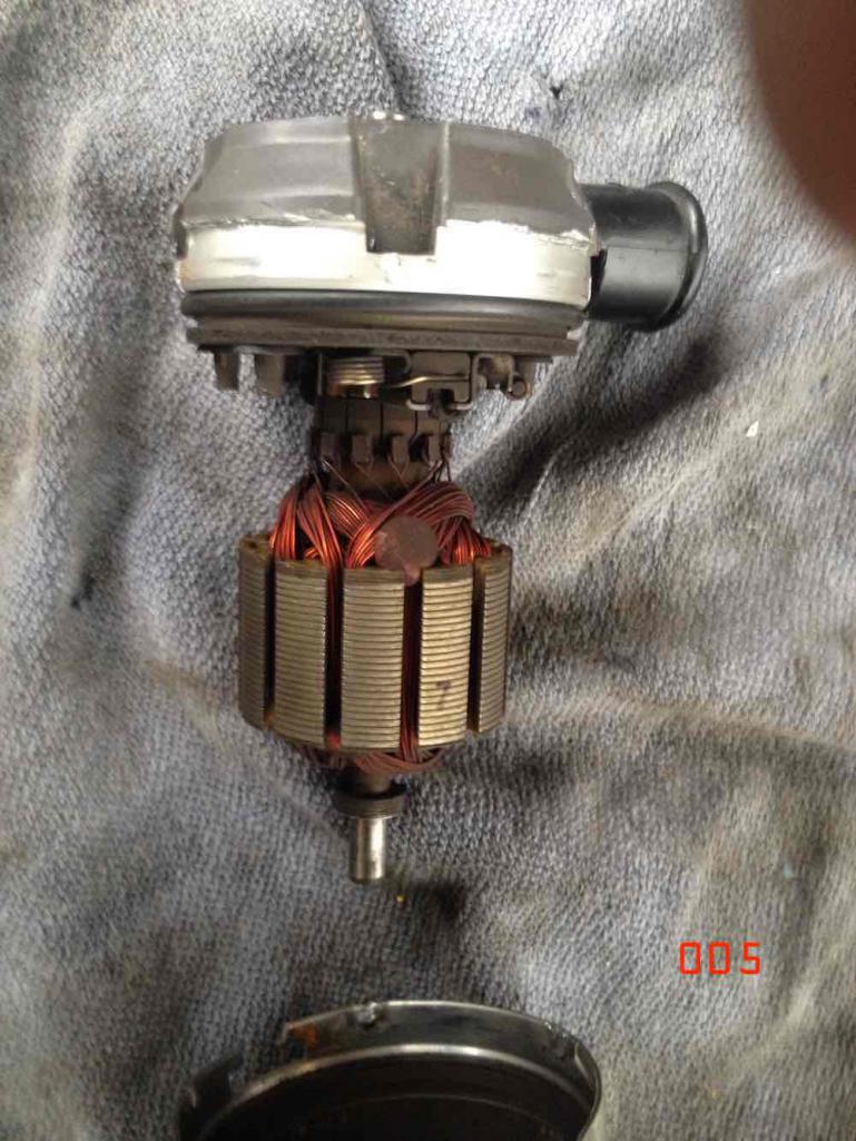 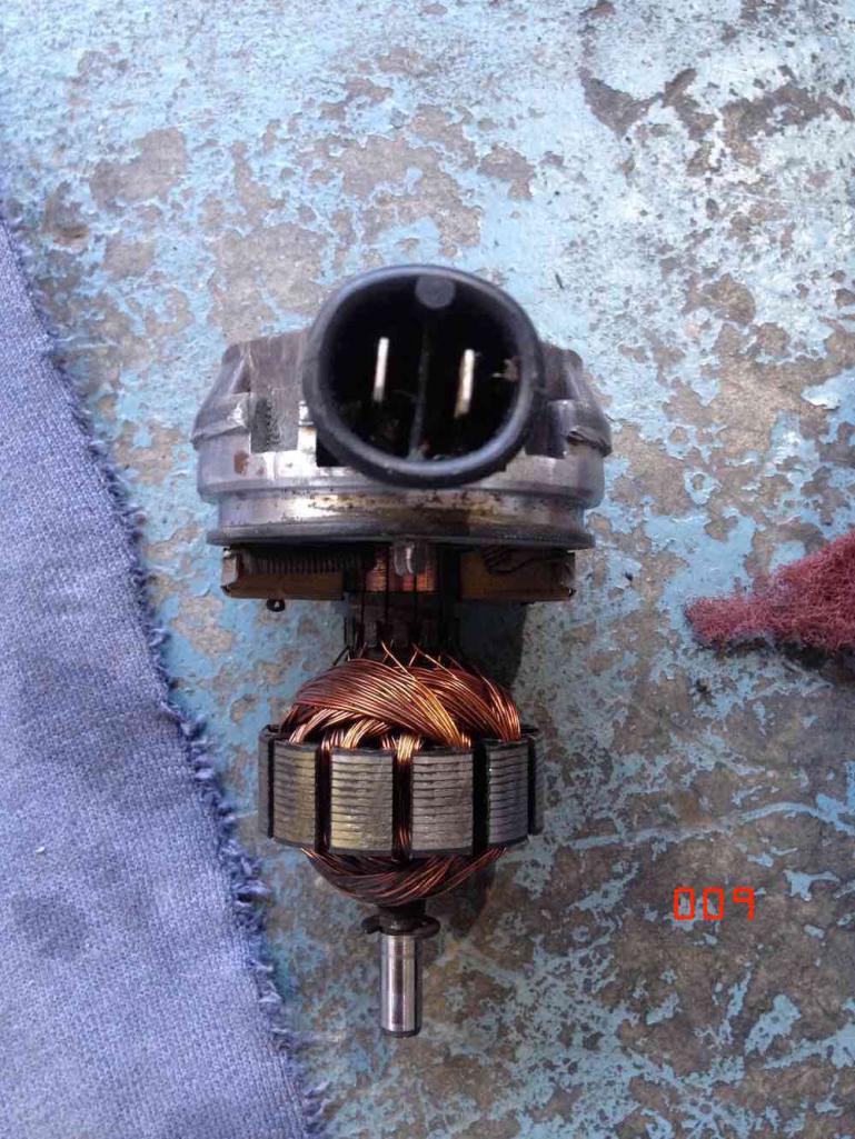 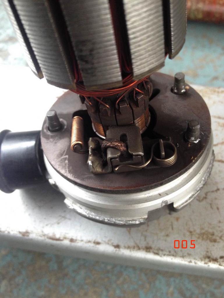 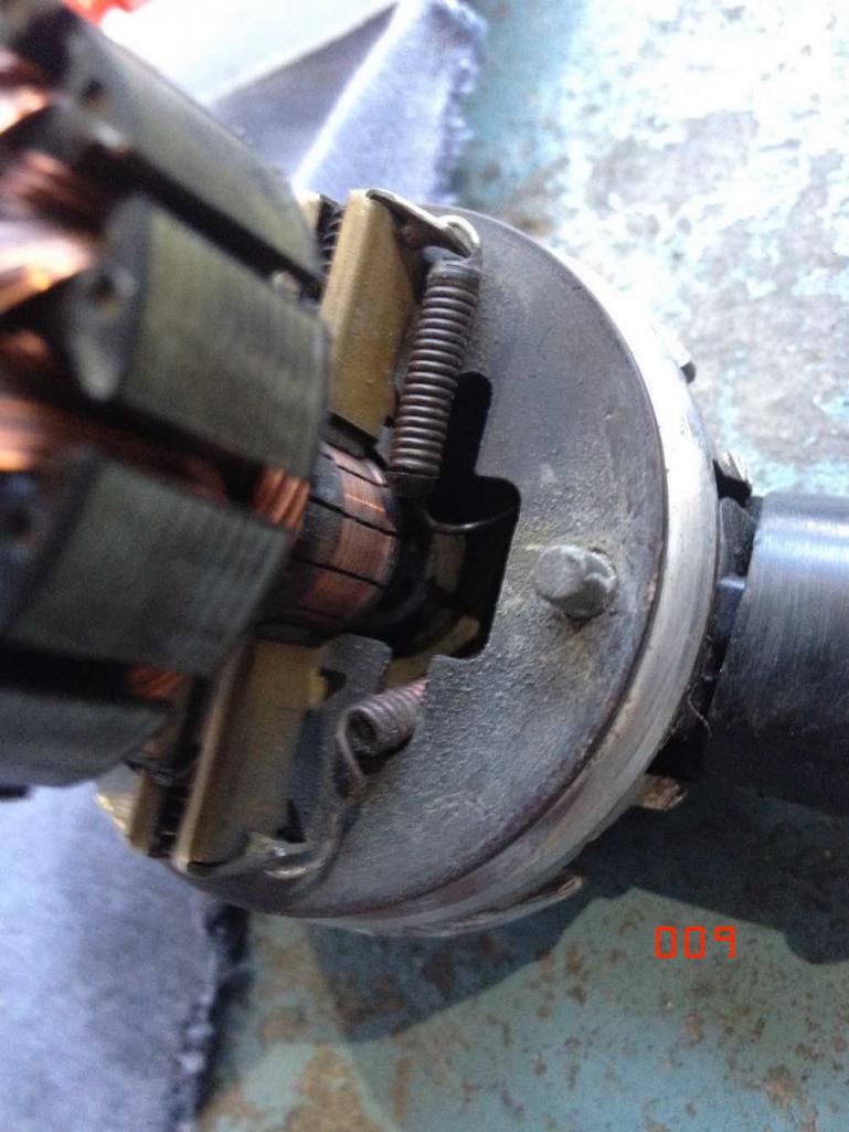 |
|
|
|
| wonkipop |
Dec 16 2020, 12:41 PM
Post
#9
|
|
914 Guru Group: Members Posts: 5,581 Joined: 6-May 20 From: north antarctica Member No.: 24,231 Region Association: NineFourteenerVille |
i made photos of the upper section of the 005 pump yesterday during disassembly.
for anyone who still runs one of these 005/009 pumps that might be leaking from the upper section the images show how easy the fix is to fit new o-rings. however most failures involving leaks or wear will be in the case section. 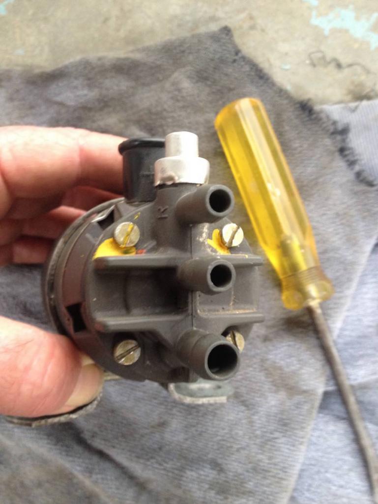 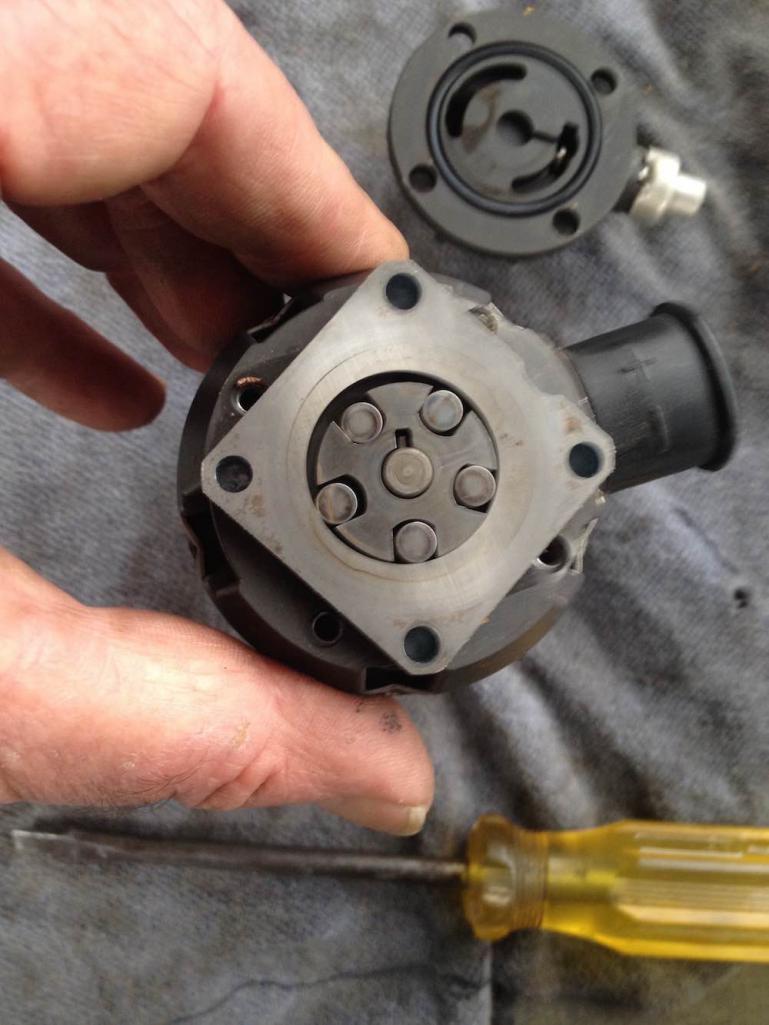 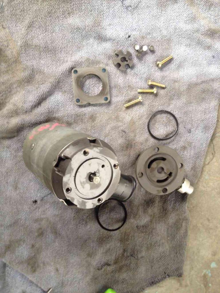 |
|
|
|
| Tdskip |
Dec 18 2020, 10:35 AM
Post
#10
|
|
Advanced Member Group: Members Posts: 3,783 Joined: 1-December 17 From: soCal Member No.: 21,666 Region Association: None |
I have one that pumps but leaks from the top below the plastic fitting, think that can be saved?
Thanks for the topic/post. |
|
|
|
| wonkipop |
Dec 18 2020, 01:31 PM
Post
#11
|
|
914 Guru Group: Members Posts: 5,581 Joined: 6-May 20 From: north antarctica Member No.: 24,231 Region Association: NineFourteenerVille |
QUOTE(Tdskip @ Dec 18 2020, 10:35 AM)  I have one that pumps but leaks from the top below the plastic fitting, think that can be saved? Thanks for the topic/post. if it runs then it probably can be saved. sounds like the electrical plug which means you will have to burrow all the way down. worst thing you might find is a well worn commutator and brushes. if you know an auto electrician reconditioner who can rebuild the commutator (and rebuild it to a good level of quality) you should end up with a good pump. as found in the pump from the mercedes once the commutator wears right down then its going to probably spit a chunk off and jam the motor (result will be sudden failure). the problem is you take the pump out of the car its off the road unless you put in another pump. the only pumps you can buy now are in-line pumps, so you will be repositioning the pump slightly and replumbing the fuel lines. the pressure relief line in these old pumps (returning fuel to the fuel return line back to the tank - its a line to a T-fitting) is not required in modern pumps with internal pressure relief. then if you put the old pump back in you will have to redo it all again back to original layout. i'm doing this because potentially i have a back up pump with the SAAB unit. with a spare pump it will be less frustrating to re-plumb back to original configuration. it won't be a hassle if the pump fails for any reason and i need to put the replacement in. just bolt up the spare and reconnect the fuel lines. i guess my advice would be if you want to think about keeping on running the original pump you might want a spare one on the shelf. if not, just go to the modern inline pump. i won't put these pumps back together until after the christmas/new year break. when i do i'll post the result of the work and whether it has been a failure. i think the challenge will be recrimping the motor housing back to the pump housing. |
|
|
|
| Tdskip |
Dec 20 2020, 04:51 PM
Post
#12
|
|
Advanced Member Group: Members Posts: 3,783 Joined: 1-December 17 From: soCal Member No.: 21,666 Region Association: None |
Funny enough my spare is from a 1971 Saab 99.
Good luck and please keep us posted mate. Best wishes for a nice holiday. |
|
|
|
| StarBear |
Dec 26 2020, 09:13 AM
Post
#13
|
|
Advanced Member Group: Members Posts: 2,327 Joined: 2-September 09 From: NJ Member No.: 10,753 Region Association: North East States |
This is marvelous. Congratulations. Maybe a sideline business for you? Our community needs/relies on such people and expertise.
BTW: While I've not tried such an adventurous effort, my adage to my wife (which constantly annoys her) is: "What am I going to do - break it more?" so go ahead and maybe 75% of the time achieve success. The latest was with our 12-year old dishwasher, just last week. Fortunately, I have just a bit enough sense to a) know when to throw up the white flag and b) not get involved in high voltage and other life-threatening situations. Keep up the great work! |
|
|
|
| wonkipop |
Jan 18 2021, 01:28 AM
Post
#14
|
|
914 Guru Group: Members Posts: 5,581 Joined: 6-May 20 From: north antarctica Member No.: 24,231 Region Association: NineFourteenerVille |
moved into assembly mode today and hit first obstacle.
def not the right o-ring on the elec connection plug. + viton very rigid it will have to be precisely correct. back to o-ring shop, revised sizing will be corrected upon full re-assembly. |
|
|
|
| wonkipop |
Jan 28 2021, 03:46 PM
Post
#15
|
|
914 Guru Group: Members Posts: 5,581 Joined: 6-May 20 From: north antarctica Member No.: 24,231 Region Association: NineFourteenerVille |
REASSEMBLY - STEP 1.
now have correct electrical plug 0-ring and successful fit. o-ring size amended in edit to list of o-rings above. electrical plug = british standard 011. thk 1.78mm OD 11.21mm. 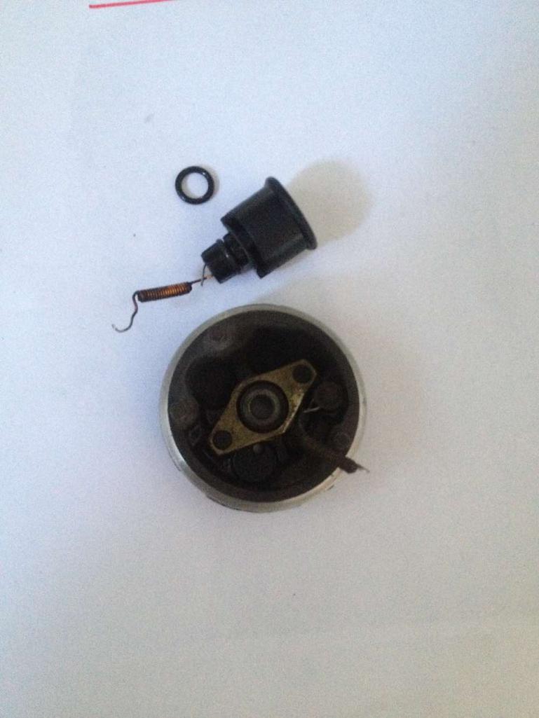 use CRC or o-ring grease to assist fitting plug into pump port base. o ring sits in a groove in the plastic plug. should not fill groove - groove allows for o-ring to expand sideways. o-ring will fit exactly into an ariss recess around the front edge of the plug hole in the base as you push the plug in. its a tight squeeze and awkward to apply pressure to. i used the soft jaw vice and gentle horizontal pressure trick. softly. a flat bladed screw driver used gently assists persuading it. you can only get the screw driver in around half of the circumference of the plug. so its mainly gentle pressure gets it to go in. i wound vice on and off gently in a cycle to massage it on. worked. 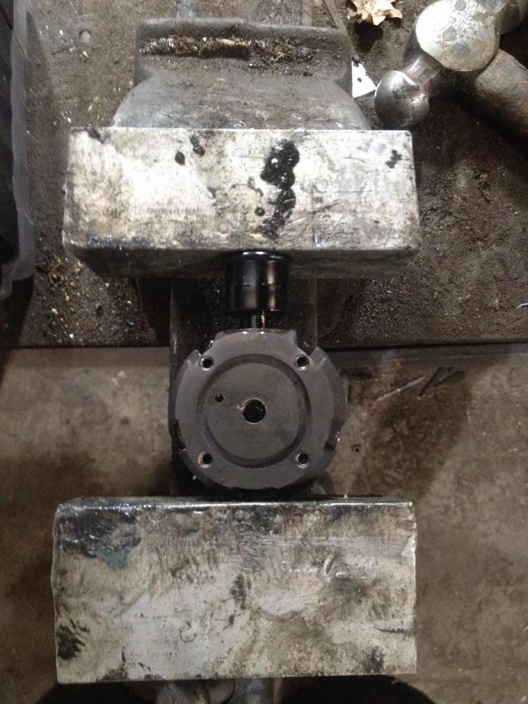 next step - bring earth wire in the plug snipped during disassembly into alignment for soldering. ideally you would overlap two portions of wire side by side to get a good joint. but there is no excess length of wire on the plug impossible to get overlap. so its a tricky solder job. 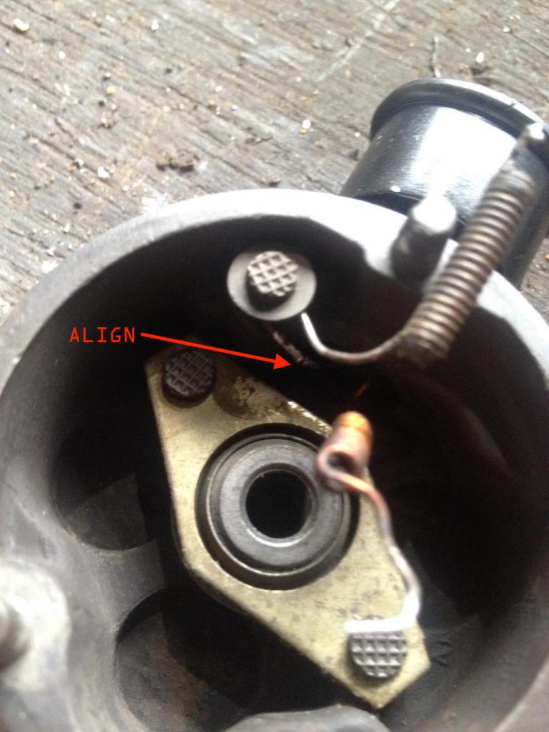 oldest pump (MERC) soldered best. tinned up straight away and was an easy join. (higher content of copper in wire? superior merc spec?) 005 pump was hard to get to tin - took two attempts to get a successful join and a lot of tin drips. 009 pump (newest of the vintage) from the 914 was a b@stard. but got it in the end after repeated failure. not much copper content in wire? 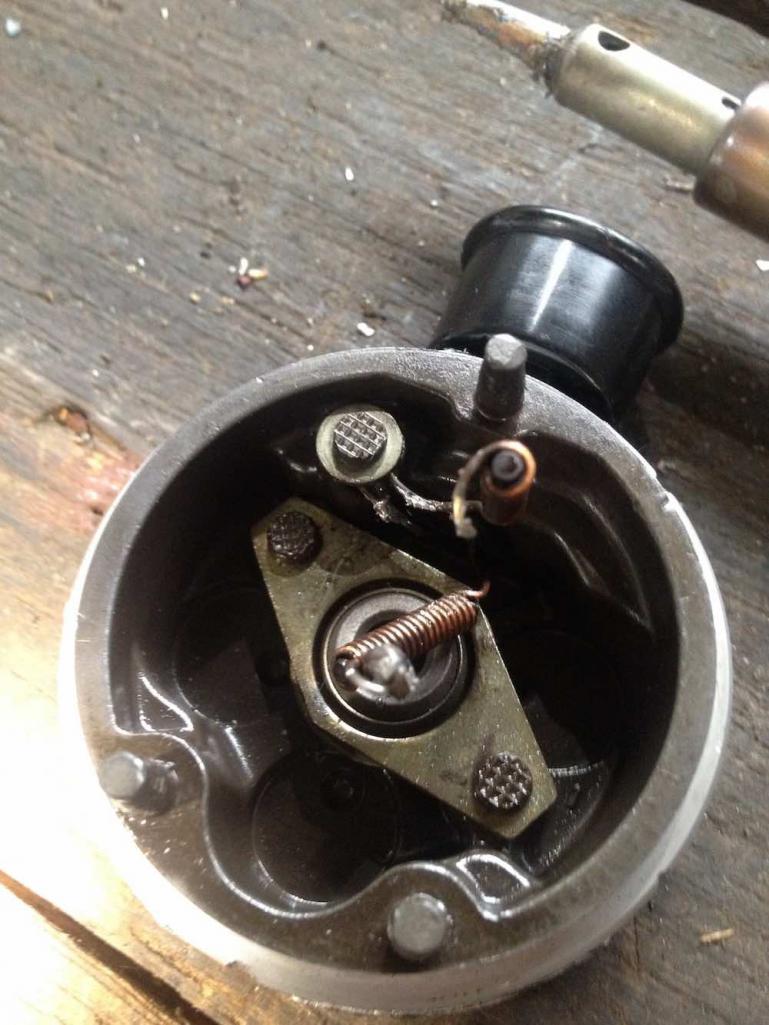 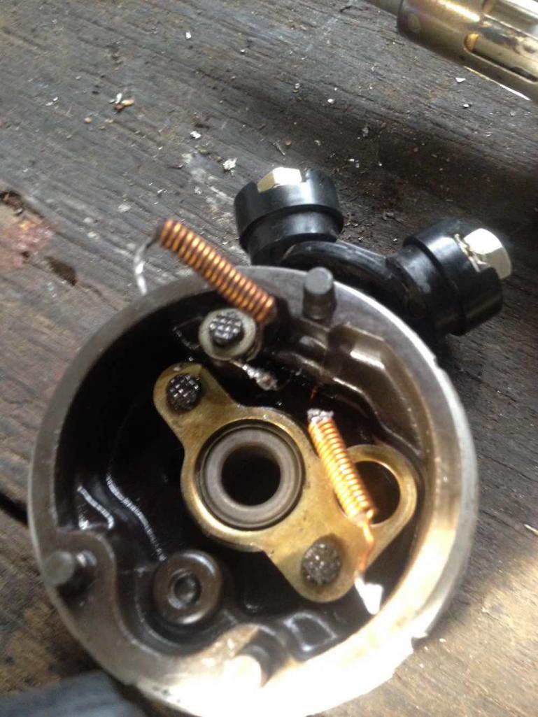 clean out the bases with electrical cleaner and air hose. ensure to get out lubricant traces and all solder drops. 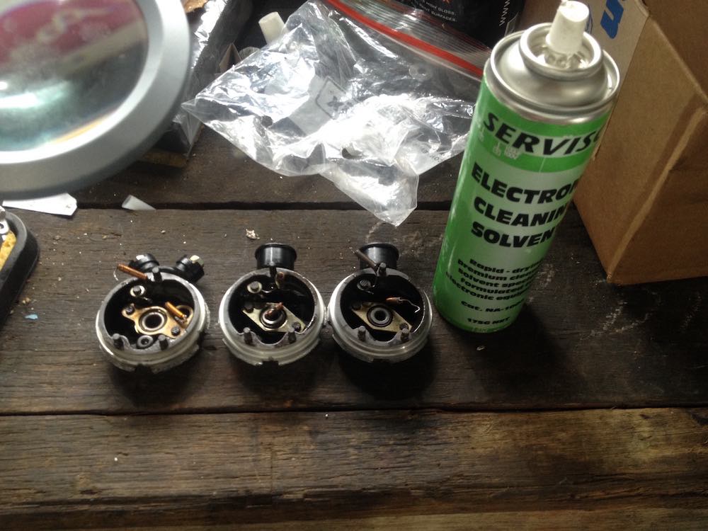 more next time. |
|
|
|
| wonkipop |
Feb 19 2021, 02:37 PM
Post
#16
|
|
914 Guru Group: Members Posts: 5,581 Joined: 6-May 20 From: north antarctica Member No.: 24,231 Region Association: NineFourteenerVille |
REASSEMBLY STEP 2
fitting the port housing inner plate & brush holder. i retained the starlock (or quicklock) washers when i disassembled. took them off carefully so good to reuse. if you damage the starlocks get some new ones. i flattened the starlock tongues using a very small socket to get them to preload again. i used a slightly larger socket to push them down on the securing pins. 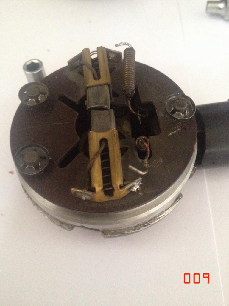 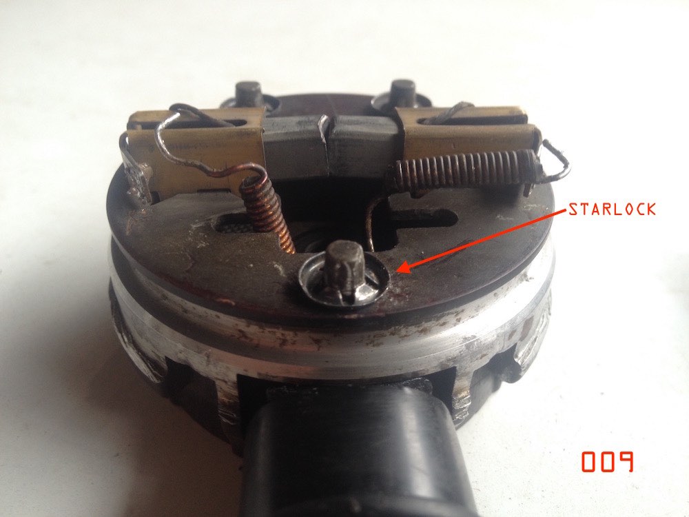 next i resoldered the spring wire connectors to the brush housings. carefully move the wires into position and push the hook ends through the slots/holes in the connection plate. i used my original disassembly photos for reference. fairly easy to see where the wires must go using logic. very difficult to make errors such as crossing the wires up accidently. both stay on the sides of the electrical plug they come out of underneath the brush plate. i did have to melt existing solder out of the holes before i could clip the wires in. once clipped solder these connections. soldering went much better than the earlier frustrations i had with the earth wire in plug base. 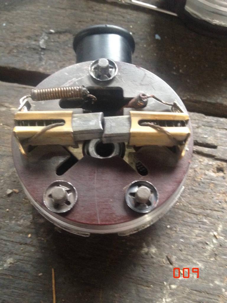 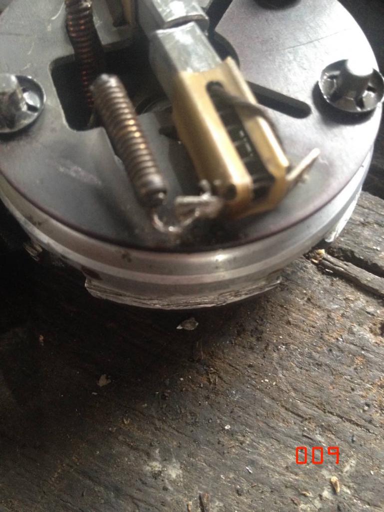 i repeated the same with the 005 pump i am reassembling. had to do a bit more work on that one. different style of brushes and electrical connections on the earlier 005 pump. one of the brush connections needed some more securing solder repair. 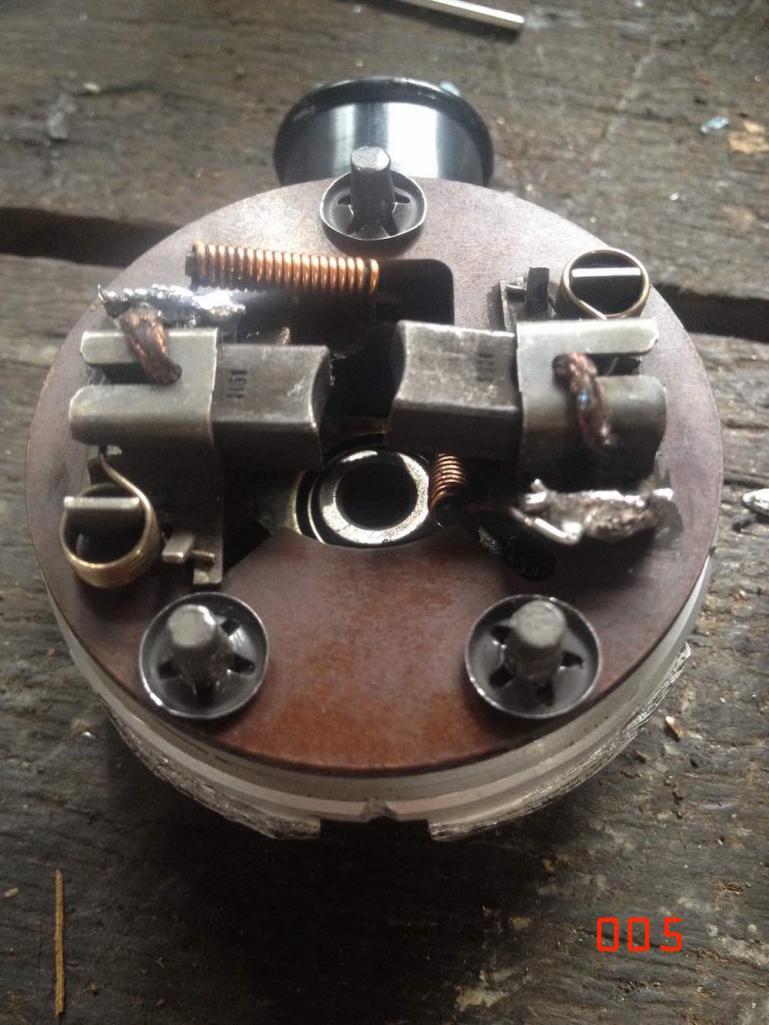 after soldering clean up any loose solder drips, blow out with air and electrical cleaner, you don't want anything trapped inside this assembly that could later break loose. |
|
|
|
| wonkipop |
Feb 19 2021, 03:09 PM
Post
#17
|
|
914 Guru Group: Members Posts: 5,581 Joined: 6-May 20 From: north antarctica Member No.: 24,231 Region Association: NineFourteenerVille |
STEP 3 - REASSEMBLING THE PORT HOUSING, MOTOR SHAFT & ARMATURE, OUTER PUMP HOUSING.
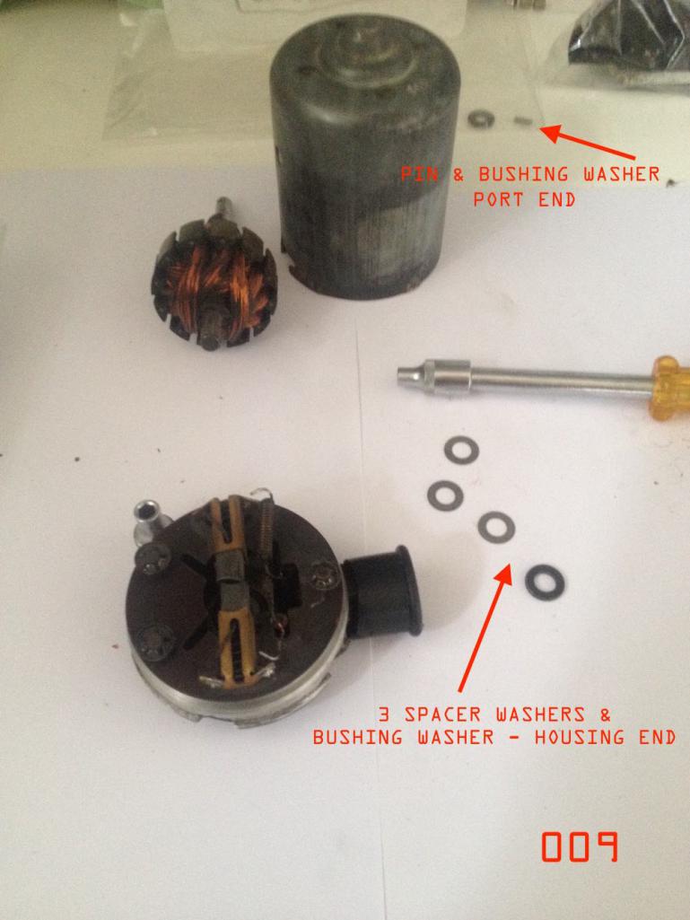 first. layout the components. as i found out disassembling both a 009 pump from a 914, and a 005 pump from a 74 SAAB EMS, each pump might be slightly differently shimmed internally. it is important to take a photo or make a record of how many shims on each end of the motor shaft. and to bag the shims separately. you want to be able to put them all back the same way they were. this ensures the brushes will align with the wear groove in the commutator. (if you recondition the commutator and brushes then i believe this is less critical). in the case of the 009 pump. pump casing end of motor shaft. there were 3 washer shims and a thicker shim or perhaps a better word would be bearing/bushing shim. the bushing shim goes on the very end of the axle and fits against the pump housing in an axle recess. port casing end of the 009 pump. there was one bearing shim on the other end of the axle. this fits against the internal side of the port housing where the axle passes through the port base housing. (on the other side of the port housing the axle is secured with a very (VERY SMALL) pin. first. fit the o-ring to the port base housing. o-ring seals the port base housing to the pump casing. size = BS 135. 2.62mm thk 54.14mm OD. lightly grease o-ring or spray CRC to stop it rolling when you fit up the pump casing. next fit the bushing washer to the port base housing end of the axle. carefully fit the motor assembly to the port base housing. you need to make sure no parts are snagging anywhere and that all wires have sufficient clearance. next refit the pin that secures the axle shaft to the port base housing. the pin also engages with the pump rotor and spins it to drive the pump. this is easier said than done. after a morning thinking about it, trying to guide it in with needle nose pliers, working on a large spread out towel to catch the pin which would very easily fly out of the pliers (and be impossible to find if you lost it) i gave up and rethought. a fitment tool was made. using a small piece of scrap flat bar steel strap. drilled a 2mm diam hole - 1 mm in from edge and 4-5 mm deep. this held the pin securely. the tool with pin and the port base housing with motor fitted were placed in a vice. the vice was used to gently push the tool with pin into the motor shaft pin hole. it took two people to do this, one to hold the assembly, one to turn the vice - smarter and more skilled people than me could probably get this together singlehandedly. the pin was tapped the remaining distance in with the side of a screwdriver. take care not to damage the surface of the port housing. this is where the fuel pump vanes and rotor spin. i did not take photos of the vice and pin tool. too intense doing it to remember to take a picture. having taken a pump apart and put it back together, getting this pin out, and then getting it back in is the most challenging part of the job. 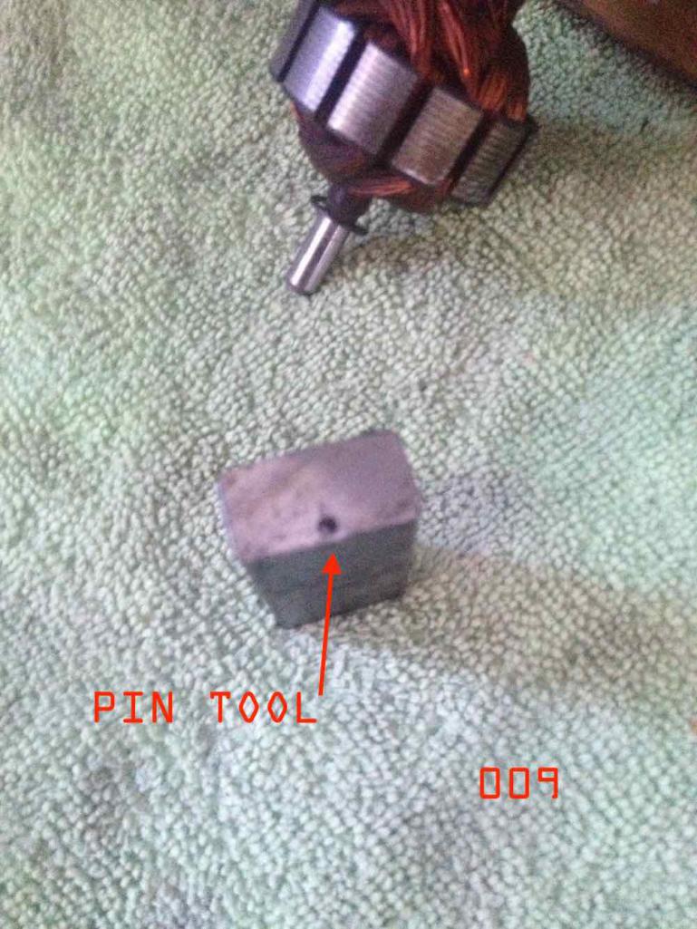  with the pin in. you can then reassemble the whole top port. this has the pump rotor, the five cylindrical pieces that fit between the rotor vanes, 2 o-rings. etc. see disassembly photos. after it is reassembled test turn it by rotating the motor. make sure it does not catch during rotation. i discovered the two o-ring seals are the things that provide correct clearance - for the pump vane to rotate in housing. (and also maybe to create correct pressure in the pump?). had to get smaller thk. o-rings than first obtained. (o-ring list has been edited to new size). after port housing is fitted together then. fit the three washers and bearing washer to the other end of the motor axle shaft. in correct order. (this number of shims applied to this particular pump). secure the washers with grease. otherwise the magnets inside the pump casing will tear the washer shims off - as you try to feed the motor assembly into the casing. i test assembled the motor assembly to the pump casing three times. to assure myself the washers were not coming off on reassembly. i put a very small amount of grease in the axle recess in the pump casing. the grease was just for initial startup when the pump was activated again. once i was sure the magnets were not tearing the washers off - i went ahead with reassembly and pushed the casing down on the motor assembly. assemble the whole thing vertically with the motor and port casing standing. bring the pump casing down on it from above. 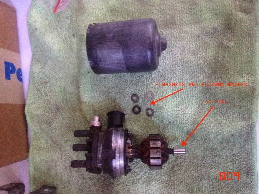 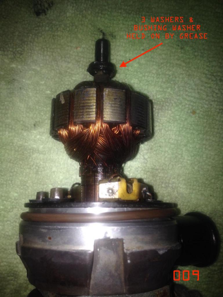 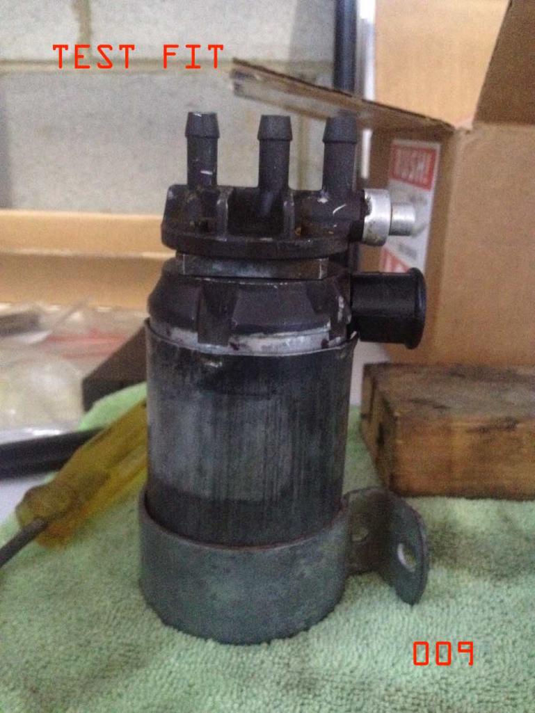 you assemble the pump casing to the port housing and motor upside down to how its shown in photo above. after you have the motor axle into the pump casing the washers and bushing washer can't come off the shaft and you can turn it around anyway you want and keep on pressing the casing on. |
|
|
|
| wonkipop |
Feb 19 2021, 03:25 PM
Post
#18
|
|
914 Guru Group: Members Posts: 5,581 Joined: 6-May 20 From: north antarctica Member No.: 24,231 Region Association: NineFourteenerVille |
STEP 4
re-crimping the pump casing to the port/pump base. another one of those moments thinking too much about how to do it. did not want to use a screwdriver and hammer as it would be too sharp? searched around the workshop for a piece of scrap metal. found a scrap of steel bar strap - was the correct width to fit the crimping recesses machined into the port/pump base. i fitted the original pump mounting bracket to the pump casing. clamped the feet of the pump mounting bracket into the vice. i could use a screwdriver to loosen and tighten the pump bracket - and spin the pump casing around to crimp each point in the pump casing. used a hammer and steel bar to gently work the crimping back in again. finished off the last bit of the crimping with a sturdy screw driver and hammer. pump all back together and ready to test. 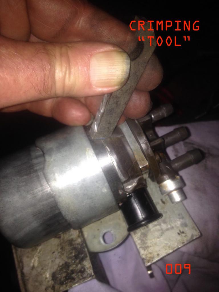 we used kerosine to test the pump. has similar if not identical viscosity to petrol fuel. has none of the harmful additives that will foul a pump if you leave it on the shelf after testing. the kerosine has similar lubricating properties to fuel - so the pump will not chew up bushings, shims etc or run hot during testing. with these pumps the fuel is providing both cooling and lubrication during operation. on the first test the pump ran. spun up straight away. but no suction and nothing was coming out of the delivery port. after a bit more coaxing and attempts to prime it began to blow fuel out of the pressure relief port. achieved weak suction feed. i stared at the three port assembly at the top of the pump and thought to myself. you have been real optimistic thinking that bit does not need to be disassembled and cleaned out. packed up the tools. job for another day. 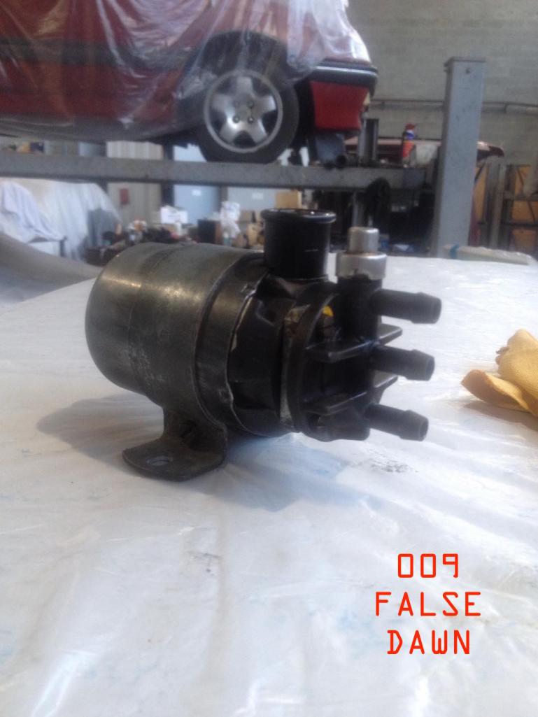 |
|
|
|
| wonkipop |
Feb 19 2021, 03:37 PM
Post
#19
|
|
914 Guru Group: Members Posts: 5,581 Joined: 6-May 20 From: north antarctica Member No.: 24,231 Region Association: NineFourteenerVille |
STEP 5 - PUMP 3 PORT TOP SECTION.
the next day. the pump 3 port casing was taken apart. here is what is inside. when you take it apart record the orientation and fit of all the components. take care when you remove the metal end cap as it may all fly apart. use fine picks to prise the crimps out of the metal cap. springs will shoot out and fly off to destinations unknown. the 009 was so gummed up the springs did not shoot out. the 005 came apart like a moon rocket going into orbit. i am still trying to think how this thing actually works. but given i got it to work again, do i really care? pressure relief in the pump is somehow accomplished by the small valve restrained in position by a spring. this valve must be able to move freely when you lever it with a screw driver. it should instantly spring back into position. i thought i had checked it for operation prior to having to pull it all apart. and it did work, but not like it works now properly cleaned. returns to position with a very positive click. the other item that required replacement was yet another o-ring. required a mid morning drive through congested post lockdown traffic to the o-ring suppliers. took the parts down with me to get the right fit the first time and get some alternatives just in case. did not remember to note down the size of the o-ring. will measure it later and post the size required. o-ring fits in the metal cap at the end of the port casing. the metal cap on the port casing has to be decrimped for disassembly. take care as its very thin tin. 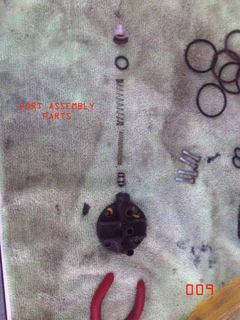 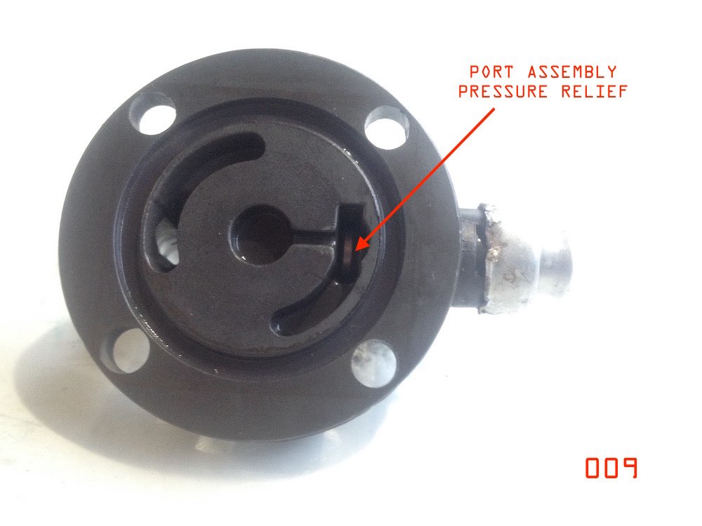 reassemble the whole thing after cleaning and fitting of new o-ring. when i refitted the pressure valve assembly cap i rotated it slightly from its original position. i could crimp it back on using undistorted metal. its very thin - like paper. crimping was done with a few taps from a small screwdriver. take care doing this as the metal is so thin it can easily tear. reassembly can be done in a vice. you have to hold it all together with one hand against the pressure of the springs. get it into the vice then carefully compress it in position. (use a socket over the cap so the broader rim is in compression, not the cap, i made this mistake on the first pump i reassembled). once restrained you can work your way around the cap and crimp it back on. if you position it in the vice to do the bottom two crimps this will be enough to hold it together to spin it in the vice and do the top crimp. all back together. 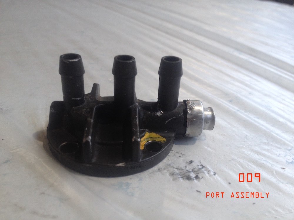 |
|
|
|
| wonkipop |
Feb 19 2021, 03:45 PM
Post
#20
|
|
914 Guru Group: Members Posts: 5,581 Joined: 6-May 20 From: north antarctica Member No.: 24,231 Region Association: NineFourteenerVille |
STEP 6 - TEST.
at the end of the day we hooked up test apparatus again. juiced up the pump. the pump transferred the contents of one kerosine bottle to another in about 30 seconds or so. i didn't have a watch on it. was just pleased it worked. initially there was a bit of discharge out of the pressure relief port but then this flow stopped. i figured that was the pressure relief valve still sticking slightly. there are two springs in there. a smaller spring inside the bigger spring. its possible the springs were catching on each other after re-assembly. if they were they sorted themselves out with a bit of test fuel pressure. once lubricated enough by kerosine everything started working fine. pump casing stayed cool so motor was not overheating. a little later we hooked up the gauge to the pump and were reading 28-32 psi pressure. figure was on spec. didn't have time to do a flow rate properly. next time. will finish reassembling the 005 pump and test them both together. no leakage was detected from any of the new o-ring seals. 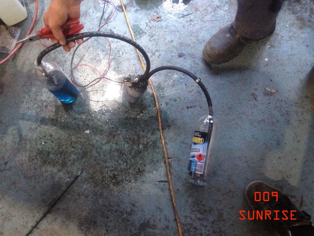 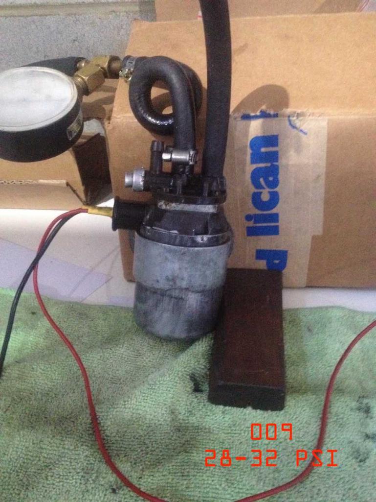 |
|
|
|
|
1 User(s) are reading this topic (1 Guests and 0 Anonymous Users)
0 Members:

|
Lo-Fi Version | Time is now: 4th July 2026 - 09:21 PM |
Invision Power Board
v9.1.4 © 2026 IPS, Inc.