|
|
|
Porsche, and the Porsche crest are registered trademarks of Dr. Ing. h.c. F. Porsche AG.
This site is not affiliated with Porsche in any way. Its only purpose is to provide an online forum for car enthusiasts. All other trademarks are property of their respective owners. |
|
|

  |

| DRPHIL914 |
 Jan 21 2021, 08:55 AM Jan 21 2021, 08:55 AM
Post
#1
|
|
Dr. Phil  Group: Members Posts: 5,947 Joined: 9-December 09 From: Kennesaw, GA Member No.: 11,106 Region Association: South East States |
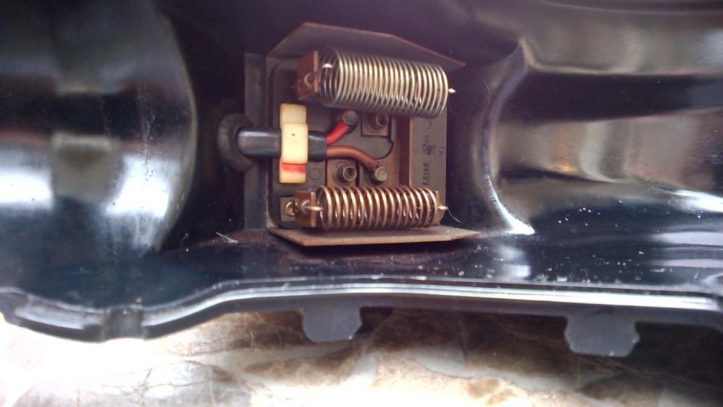
I have been dealing with this for 12 years, a non-running defrost fan. i even pulled this out 2 years ago and rebuilt it with new flapper seals and main body seal then made sure fan turned but didnt bench test the motor or resisitors, so as a result it still does not work properly. i will be documenting this because 914rubber and Mark will soon be putting together a kit for this that includes all the hardware seals and even a motor i believe, BUT i still have problems and questions!!! so i am starting this thread to get information on diagnosing the common causes of it not working and how to fix it, and then document the rebuild and replacement of the motor, fan, resistor and maybe the control unit in dash. Others have documented the reinstallation of the fan and the cables so i will not duplicate that. and we may want to link other threads hear that have done that as well.
Mark is sending me a kit soon, so while i wait for it, i will have to get some more information about the wiring and resistors function and how to test them . I had this out last week and tested 3 different control units due to thinking that my issue was a control issue, because it runs on one speed, #2, and anything else does not work and it will then throw the fuse. most assume this would be caused by bad slider unit but i tested 3 of them and 2 are like new with no wear on the sliders , still same result. so i am suspecting the resistors /plug aparatus . If anyone has done this and cares to share how to examine and test that for proper function, lets start there. Resistor function, which lead is which and examination of the control units I will take pictures of mine tonight and post those soon. once this figured out and fixed i will do a full step bystep on reassembly too. Looking for lots of help and input on this, thanks!!! Dr. Phil |
   |

 
|
| Superhawk996 |
Jan 21 2021, 09:43 AM
Post
#2
|
|
914 Guru Group: Members Posts: 7,888 Joined: 25-August 18 From: Woods of N. Idaho Member No.: 22,428 Region Association: Galt's Gulch |
Not trying to be a jerk here. But I keep seeing a pattern in the forum when people are stuggling with electrical issues.
Rule #1: Don't assume anything Rule #2: You MUST have a schematic and understand how to read and use it. Rule #3: You must have a DMM Rule #4: Learn the 1/2 split method (Google or PM me) Rule #5: You must follow a methodical approach. If you're not already familiar with DC motor theory, spend some time on Google to understand that too. Chasing other people's assumptions of what might be the cause and/or fixes that once worked for so and so will lead you on a path to nowhere. |
|
|
|
| DRPHIL914 |
Jan 21 2021, 11:01 AM
Post
#3
|
|
Dr. Phil Group: Members Posts: 5,947 Joined: 9-December 09 From: Kennesaw, GA Member No.: 11,106 Region Association: South East States |
QUOTE(Superhawk996 @ Jan 21 2021, 10:43 AM)  Not trying to be a jerk here. But I keep seeing a pattern in the forum when people are stuggling with electrical issues. Rule #1: Don't assume anything Rule #2: You MUST have a schematic and understand how to read and use it. Rule #3: You must have a DMM Rule #4: Learn the 1/2 split method (Google or PM me) Rule #5: You must follow a methodical approach. If you're not already familiar with DC motor theory, spend some time on Google to understand that too. Chasing other people's assumptions of what might be the cause and/or fixes that once worked for so and so will lead you on a path to nowhere. soooo maybe you've missed the main thrust of this , which is to document a rebuild process, but also the trouble shooting and diagnosis of the common causes of failure of this unit., mainly for those with less experience in working with electrical issues. 1- nothing here has been or is assumed 2- i have the schematics on the laminated sheets - most have never had any electronics or wiring classes, i have ha some but many years ago 4 - i always search the forum and google for same or similar topic, and have done so regarding this extensively , only one thread comes up with any explanation of the resistor connections by @beatnavy and that does not really look into testing or replacing the resistors 5- thats the plan regarding my own current situation ive verified power to the source, proper ground, and just a basic trial and error experiment found the change of controllers made no change. so i could have 3 controllers that all have exactly the same issue OR more likely the issue is at the fan and resistors. SO have you sir gone thru this process with this unit? if you have do you have some constructive advice or experience specifically regarding it? if so please post. since i am not an electrician i may also be asking how to interpret the schematic. but yes i agree your list of the above suggestions is not a bad , yes you kind of do come across as a bit of a jerk , sorry, if that is all you are contributing here. with that said i am no rookie here having essentially taken this car apart and put tit back together in the past 12 years, and how did i do that? with a lot of time and energy in research and internet searching and a lot of stupid questions getting valuable answers here on this forum. I would never have started this post if there were already a nice clear concise description on the subject (its not just the electrical issue as i stated in my first post but also to document the rebuild) |
|
|
|
| BeatNavy |
Jan 21 2021, 11:41 AM
Post
#4
|
|
Certified Professional Scapegoat Group: Members Posts: 2,963 Joined: 26-February 14 From: Easton, MD Member No.: 17,042 Region Association: MidAtlantic Region |
Phil, if it runs on one speed but not another (or the other two), it's likely a blown resistor. Too much resistance builds up through the ground circuit and it fries. I remember shortly after putting mine back in after cleaning it up -- I put it on low speed and saw a little puff of smoke came up through the vent grill. IIRC it uses three resistors in different combinations to control the effective voltage supplied to the motor. I have a fresh resistor pack that BillC sold me a few months ago. I'll see if I can find that for reference (although doing this wasn't high on my priority list, so I may have buried it with my other parts that I'll get to "one day.")
|
 |
|
| DRPHIL914 |
Jan 21 2021, 12:05 PM
Post
#5
|
|
Dr. Phil Group: Members Posts: 5,947 Joined: 9-December 09 From: Kennesaw, GA Member No.: 11,106 Region Association: South East States |
QUOTE(BeatNavy @ Jan 21 2021, 12:41 PM) Phil, if it runs on one speed but not another (or the other two), it's likely a blown resistor. Too much resistance builds up through the ground circuit and it fries. I remember shortly after putting mine back in after cleaning it up -- I put it on low speed and saw a little puff of smoke came up through the vent grill. IIRC it uses three resistors in different combinations to control the effective voltage supplied to the motor. I have a fresh resistor pack that BillC sold me a few months ago. I'll see if I can find that for reference (although doing this wasn't high on my priority list, so I may have buried it with my other parts that I'll get to "one day.") thats kind of what i figured, i found your thread from a couple years ago, you were working thru your issue and had figured out which wire was what. I have 2 other fan boxes and i hope i have one good resistor pack , because i have tried looking and have not found any out there id dont think they can be bought anymore. i might post a WTB ad on classifieds here as well. thanks for the input! Phil |
|
|
|
| mepstein |
Jan 21 2021, 12:08 PM
Post
#6
|
|
914-6 GT in waiting Group: Members Posts: 20,773 Joined: 19-September 09 From: Landenberg, PA/Wilmington, DE Member No.: 10,825 Region Association: MidAtlantic Region |
Just like starter motors and alternator, the climate control motors can be rebuilt. Usually cheaper than new and often better built. Plus you know the fit and specs are exact.
|
|
|
|
| framos914 |
Jan 21 2021, 12:18 PM
Post
#7
|
|
Member Group: Members Posts: 125 Joined: 15-May 14 From: Corona California Member No.: 17,353 Region Association: Southern California |
I went through this a few months ago. Since I had the gas tank out, I thought I would tackle the non working defrost fan. I removed the fan for bench testing.
I checked resistance between the hot pin on the unit and each of the other 3 pins. I did get 3 different resistance values (should have noted the resistance values). Next I connected 12 volts to the unit and applied ground to each of the other 3 pins. I got the 3 different speeds. I turned my attention to the control lever. Since none of the 3 speeds worked I concentrated on the part of the slider contacts that was common to all 3 wires. Must have just been corroded because after a good cleaning of all contact surfaces the fan worked normal. I removed, cleaned and lubed the windshield wiper assembly while I was in there. Of course it was a PITA reinstalling the fan. Ian has a good video on how to install fan. |
|
|
|
| Superhawk996 |
Jan 21 2021, 12:29 PM
Post
#8
|
|
914 Guru Group: Members Posts: 7,888 Joined: 25-August 18 From: Woods of N. Idaho Member No.: 22,428 Region Association: Galt's Gulch |
I'm here to help. Not trying to be a jerk. Apologize if it's coming off that way, I'm an engineer so it comes naturally. (IMG:style_emoticons/default/laugh.gif)
https://www.youtube.com/watch?v=9LaV8lSdOHQ I have a copy of Prospero's garage laminated schematic. Nice for some things like color codes but sucks for others. Not sure if this is what you have. For the ventillation fan work, it is closer to sucks. The fresh air fan has no component detail on what in there, only a block diagram. Haynes manual is better IHMO. @bbrock recently tore into his resistor pack. I can't seem to find the thread at the moment. There are two wire coil resistors. They control Low and medium. High is wired w/o a resistor to motor per Haynes (white wire) . There is also a bi-metallic thermal cut out switch per the Haynes schematic. The resistors and thermal cutout switches can be verified with DMM. Unfortunately the Haynes manual isn't clear on how the bimetallic switch is physcially built. Brent's photo's I think had detail. The Haynes manual does show that if the switch is closed, it bypasses the resitor, drives the fan at full speed, and then cools off the wire resistor coil, at which point the bimetallic switch should open again and slow the fan to proper speed. With respect to the control levers, have you verified the connections and continuity with DMM? "so i could have 3 controllers that all have exactly the same issue OR more likely the issue is at the fan and resistors" As you state, you could have 3 bad units (not likely) but a quick continuity and/or resistance test with a DMM will verify them and remove any doubt. That is sort of what I was implying by making assumptions. Don't assume that and/or jump to conclusion is at the fan and resistors. Not trying to beat you up on this. It's a very common thing to do that can lead you astray and lot's of people make these sort of inferences when trying to do electical work. Comment above from @framos914 is spot on as we was basically using a half split method either knowingly or by intuition. The reason I mention DC motor theory is because if you have a motor that isn't free to spin (bad bearings/bushing) it will draw more current than it should and could blow the fuse and/or not even rotate on the lower speed. Likewise, if you have shorted windings in the motor, it could blow fuses. We can verify each of these possibilities in a methodical way. But, let's not get ahead of it yet. |
|
|
|
| BeatNavy |
Jan 21 2021, 12:30 PM
Post
#9
|
|
Certified Professional Scapegoat Group: Members Posts: 2,963 Joined: 26-February 14 From: Easton, MD Member No.: 17,042 Region Association: MidAtlantic Region |
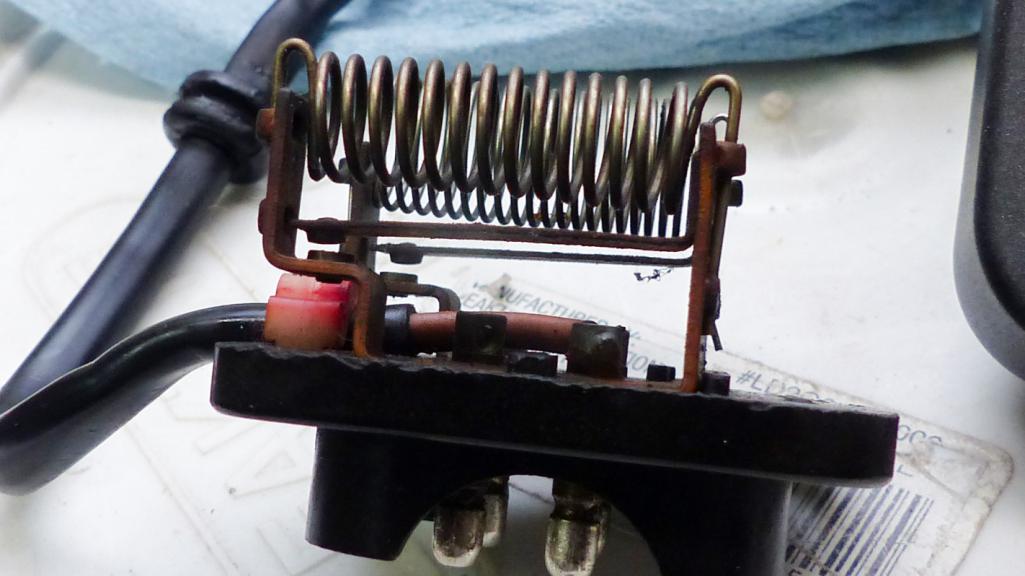
So I found the resistor pack. And I found my old photos. Looking at the resistor pack I acquired I can now see values on there that I never noticed before. There are two resistors. The one on top is 2.5 ohms and the one in bottom is .75 ohms. So there are three settings. I'm assuming high speed runs through neither resistor, medium through one (maybe the .75 ohm resistor), and low through both for 3.25 ohms of resistance. Probably 50 watt at least.
 Edit: And to Superhawk's point, when I managed to get my motor spinning, I never really fully rebuilt it, so it probably wasn't spinning as freely as is should. That means more power draw through that resistor at low speed than it was designed for, and (IMG:style_emoticons/default/blowup.gif) |
|
|
|
| Superhawk996 |
Jan 21 2021, 01:11 PM
Post
#10
|
|
914 Guru Group: Members Posts: 7,888 Joined: 25-August 18 From: Woods of N. Idaho Member No.: 22,428 Region Association: Galt's Gulch |
I'm also going to throw another one out there. You didn't mention which fuse was blowing.
Is it pulling power from the proper fuse? Should be fuse #8 - 25A fuse. |
|
|
|
| Superhawk996 |
Jan 21 2021, 01:22 PM
Post
#11
|
|
914 Guru Group: Members Posts: 7,888 Joined: 25-August 18 From: Woods of N. Idaho Member No.: 22,428 Region Association: Galt's Gulch |
page 72 post #1439
 http://www.914world.com/bbs2/index.php?sho...290&st=1420 Here is the detail on the bi-metallic switch BELOW the resistor. @bbrock problem was only two speeds. Fully acknowlege this is different than your problem but it does detail how the switches are physcially built if you wish to document this thoroughly. |
|
|
|
| BeatNavy |
Jan 21 2021, 01:50 PM
Post
#12
|
|
Certified Professional Scapegoat Group: Members Posts: 2,963 Joined: 26-February 14 From: Easton, MD Member No.: 17,042 Region Association: MidAtlantic Region |
Ahhh...ok, that filled in at least some of the missing pieces for me. I think I have a better idea how this thing works.
Amazing how complicated it is and how much engineering went in to this little bugger. |
|
|
|
| Superhawk996 |
Jan 21 2021, 02:06 PM
Post
#13
|
|
914 Guru Group: Members Posts: 7,888 Joined: 25-August 18 From: Woods of N. Idaho Member No.: 22,428 Region Association: Galt's Gulch |
Here's a few links about the 1/2 split method. This is method of troubleshooting that was taught to me by USAF as the quickest way to troubleshoot electrical equipment. It works. More than happy to elaborate if I can assist. Unfortunately words aren't the best way to describe the process but at the same time I haven't found a great video yet.
I've posted these intermittently in other threads where people are troubleshooting electical systems and some have PM'd me that they found them to be helpful. https://www.ecmweb.com/maintenance-repair-o...f-halfsplitting https://rule11.tech/troubleshooting-half-split/ https://artoftroubleshooting.com/2013/04/25...ear-up-to-here/ |
|
|
|
| Superhawk996 |
Jan 21 2021, 02:07 PM
Post
#14
|
|
914 Guru Group: Members Posts: 7,888 Joined: 25-August 18 From: Woods of N. Idaho Member No.: 22,428 Region Association: Galt's Gulch |
QUOTE(BeatNavy @ Jan 21 2021, 02:50 PM) Amazing how complicated it is and how much engineering went in to this little bugger. Yup, typical German part! |
|
|
|
| 914_teener |
Jan 21 2021, 02:21 PM
Post
#15
|
|
914 Guru Group: Members Posts: 5,270 Joined: 31-August 08 From: So. Cal Member No.: 9,489 Region Association: Southern California |
Glad you guys are getting along.
I did this years ago....twice. Fixed the fan and then the wiper motor gave up the ghost. Sage advice: Don't do one without checking the other. The only way to replace the wiper motor is by taking back out the fresh air box and then fan...and then wiper assembly. Turns out when the OP turned on the fan after it filled up with leaves it burned out the resister and overloaded the wire harness burning it and then shorting to the wiper part of the harness....... Taking this out twice and tracing down the short and in that process I believe new expletives were invented. So.....test both while your there. |
|
|
|
| DRPHIL914 |
Jan 21 2021, 04:34 PM
Post
#16
|
|
Dr. Phil Group: Members Posts: 5,947 Joined: 9-December 09 From: Kennesaw, GA Member No.: 11,106 Region Association: South East States |
QUOTE(Superhawk996 @ Jan 21 2021, 01:29 PM) I'm here to help. Not trying to be a jerk. Apologize if it's coming off that way, I'm an engineer so it comes naturally. (IMG:style_emoticons/default/laugh.gif) https://www.youtube.com/watch?v=9LaV8lSdOHQ I have a copy of Prospero's garage laminated schematic. Nice for some things like color codes but sucks for others. Not sure if this is what you have. For the ventillation fan work, it is closer to sucks. The fresh air fan has no component detail on what in there, only a block diagram. Haynes manual is better IHMO. @bbrock recently tore into his resistor pack. I can't seem to find the thread at the moment. There are two wire coil resistors. They control Low and medium. High is wired w/o a resistor to motor per Haynes (white wire) . There is also a bi-metallic thermal cut out switch per the Haynes schematic. The resistors and thermal cutout switches can be verified with DMM. Unfortunately the Haynes manual isn't clear on how the bimetallic switch is physcially built. Brent's photo's I think had detail. The Haynes manual does show that if the switch is closed, it bypasses the resitor, drives the fan at full speed, and then cools off the wire resistor coil, at which point the bimetallic switch should open again and slow the fan to proper speed. With respect to the control levers, have you verified the connections and continuity with DMM? "so i could have 3 controllers that all have exactly the same issue OR more likely the issue is at the fan and resistors" As you state, you could have 3 bad units (not likely) but a quick continuity and/or resistance test with a DMM will verify them and remove any doubt. That is sort of what I was implying by making assumptions. Don't assume that and/or jump to conclusion is at the fan and resistors. Not trying to beat you up on this. It's a very common thing to do that can lead you astray and lot's of people make these sort of inferences when trying to do electical work. Comment above from @framos914 is spot on as we was basically using a half split method either knowingly or by intuition. The reason I mention DC motor theory is because if you have a motor that isn't free to spin (bad bearings/bushing) it will draw more current than it should and could blow the fuse and/or not even rotate on the lower speed. Likewise, if you have shorted windings in the motor, it could blow fuses. We can verify each of these possibilities in a methodical way. But, let's not get ahead of it yet. QUOTE(Superhawk996 @ Jan 21 2021, 02:11 PM) I'm also going to throw another one out there. You didn't mention which fuse was blowing. Is it pulling power from the proper fuse? Should be fuse #8 - 25A fuse. QUOTE(Superhawk996 @ Jan 21 2021, 02:22 PM) page 72 post #1439 http://www.914world.com/bbs2/index.php?sho...290&st=1420 Here is the detail on the bi-metallic switch BELOW the resistor. @bbrock problem was only two speeds. Fully acknowlege this is different than your problem but it does detail how the switches are physcially built if you wish to document this thoroughly. (IMG:style_emoticons/default/aktion035.gif) hey its all good, sometimes things come across different in print, but really no offense taken, i can see that engineering mind go to work! my son and my nephew are both engineers, my electrons choose the path of least resistance (IMG:style_emoticons/default/av-943.gif) and went with the spinal biomechanical engineering( chiropractor) but really got into the functional biomechanics, always loved learning how everyting works , still learning and digging in on this stuff, but i digress--- - thanks for pointing out the continuity on the controller i will recheck that and compare the other units , i did that a few years ago so will recheck and document it. - i have a free turning fan, that seems good on this unit , not my spare unit. - mark and Matt are thinking similar in rebuilding the motor, new ones Bosch are $80 or so, not expensive, but not cheap either. -i need to check but pretty sure its fuse #8 being blown if its not that means someone has been messing around. I went thru the whole harness and fuse box when i installed the new box with blade fuses a few years ago. but again i need to not assume but re-verify. then need to measure the resistance of these 3 circuits on each unit i have. I wonder if the spring in essence is your resistor but is broken and we know the needed value, should be able to rebuild that i would think right? first things first. BTW @Superhawk996 - have read all your build thread since it started, you also have mad fab skills, wish i had the room for doing that kind of work, i had to outsource mine but that ended up being worth at the time, you know time vs money and i dont have a lot of either but still working so thats the way it went. lots of great infor hear already, will get at measuring and checking on these items and get back here soon. Phil |
|
|
|
| Superhawk996 |
Jan 21 2021, 05:01 PM
Post
#17
|
|
914 Guru Group: Members Posts: 7,888 Joined: 25-August 18 From: Woods of N. Idaho Member No.: 22,428 Region Association: Galt's Gulch |
QUOTE(DRPHIL914 @ Jan 21 2021, 05:34 PM) I wonder if the spring in essence is your resistor but is broken and we know the needed value, should be able to rebuild that i would think right? @DRPHIL914 Thank you for the kind words regarding the rebuild of my (IMG:style_emoticons/default/stromberg.gif)! Just for clarity, it isn't a spring per se. It is basically a wire wound resistor without a housing just suspended in air. The resistive coil is exposed to air flow and is air cooled (like the engine). Pretty neat huh? If the coils were touching one another, resistance would decrease. If it breaks or goes Poof and opens up, now you have infinite resistance. Either of these scenarios can be checked with a DMM. In @BeatNavy 's case, if he had a stalled motor (or very slow spinning motor), the low speed resistive element probably got too hot both from too much current draw (from the stalled motor) and lack of cooling from no airflow and then the smoke got out. (IMG:style_emoticons/default/hissyfit.gif) Not so simple to repair but not impossible in concept. The resistive wire is a special alloy designed both for stable resistance per unit of length as well as good thermal properties (doesn't melt easily, stable resistance at various temperatures, etc.). Here is the Wiki on what it could be. https://en.wikipedia.org/wiki/Resistance_wire Nichrome and Magnanin are the most common. Much easier to find a donor and replace if it turns out to be a resistor. If I had to McGyver something, I'd start looking at toasters for their resistive elements but that would take some real trial and error to understand if it could even be done. (IMG:style_emoticons/default/huh.gif) (IMG:style_emoticons/default/sheeplove.gif) More seriously speaking, I'd start looking to other more readily avilable domestic blower motors to see if I could find a similar wire resistive element and would cobble that. Alternatively, you could replace the resistor with say 12 gauge copper wire (zero ohms resistance) and you would esentially have two HIGH speeds. Or I guess, you could just bend the bi-metallic switch contact to be closed all the time. Same result - bypasses the resistor. That was what caused @bbrock 's problem. With a little math we could roll (i.e. wind) our own. (IMG:style_emoticons/default/smoke.gif) https://www.amazon.com/Nichrome-80-Gauge-Re...F9N7AHK43ZF4CP8 Many thanks to Brent for photographing and documenting that bugger! |
|
|
|
| bbrock |
Jan 21 2021, 08:31 PM
Post
#18
|
|
914 Guru Group: Members Posts: 5,269 Joined: 17-February 17 From: Montana Member No.: 20,845 Region Association: Rocky Mountains |
@Superhawk996 I can't believe you were able to dig that out of my thread. I had forgotten all about it. And yes, my problem was that my blower switch positions went low, high, high. So the blower worked in all positions, but medium speed was missing as it was going straight to high because of that little breaker gizmo.
As for repairing a blown resistor - how important do you suppose it is to use an open coil resistor. Would something like this work as a replacement? (IMG:https://media.digikey.com/Photos/TE%20Connectivity/HS,-CGS-51.jpg) https://www.digikey.com/en/products/detail/...A502R5J/2366322 It's funny. I have a roll of nichrome wire left over from a failed attempt to build a DIY plexiglass bender many years ago. I remember when I was trouble shooting my blower that I might finally get to use that wire to wind a new resistor. Alas, it was not to be... |
|
|
|
| DRPHIL914 |
Jan 21 2021, 08:33 PM
Post
#19
|
|
Dr. Phil Group: Members Posts: 5,947 Joined: 9-December 09 From: Kennesaw, GA Member No.: 11,106 Region Association: South East States |
QUOTE(Superhawk996 @ Jan 21 2021, 06:01 PM) QUOTE(DRPHIL914 @ Jan 21 2021, 05:34 PM) I wonder if the spring in essence is your resistor but is broken and we know the needed value, should be able to rebuild that i would think right? @DRPHIL914 Thank you for the kind words regarding the rebuild of my (IMG:style_emoticons/default/stromberg.gif)! Just for clarity, it isn't a spring per se. It is basically a wire wound resistor without a housing just suspended in air. The resistive coil is exposed to air flow and is air cooled (like the engine). Pretty neat huh? If the coils were touching one another, resistance would decrease. If it breaks or goes Poof and opens up, now you have infinite resistance. Either of these scenarios can be checked with a DMM. In @BeatNavy 's case, if he had a stalled motor (or very slow spinning motor), the low speed resistive element probably got too hot both from too much current draw (from the stalled motor) and lack of cooling from no airflow and then the smoke got out. (IMG:style_emoticons/default/hissyfit.gif) Not so simple to repair but not impossible in concept. The resistive wire is a special alloy designed both for stable resistance per unit of length as well as good thermal properties (doesn't melt easily, stable resistance at various temperatures, etc.). Here is the Wiki on what it could be. https://en.wikipedia.org/wiki/Resistance_wire Nichrome and Magnanin are the most common. Much easier to find a donor and replace if it turns out to be a resistor. If I had to McGyver something, I'd start looking at toasters for their resistive elements but that would take some real trial and error to understand if it could even be done. (IMG:style_emoticons/default/huh.gif) (IMG:style_emoticons/default/sheeplove.gif) More seriously speaking, I'd start looking to other more readily avilable domestic blower motors to see if I could find a similar wire resistive element and would cobble that. Alternatively, you could replace the resistor with say 12 gauge copper wire (zero ohms resistance) and you would esentially have two HIGH speeds. Or I guess, you could just bend the bi-metallic switch contact to be closed all the time. Same result - bypasses the resistor. That was what caused @bbrock 's problem. With a little math we could roll (i.e. wind) our own. (IMG:style_emoticons/default/smoke.gif) https://www.amazon.com/Nichrome-80-Gauge-Re...F9N7AHK43ZF4CP8 Many thanks to Brent for photographing and documenting that bugger! thanks for explanation, it’s fascinating, it is “cool” , and actually amazing how they worked all that out. all fast would be better than none at all , i need to test mine this weekend so i know what i am looking at. |
|
|
|
| Superhawk996 |
Jan 22 2021, 06:56 AM
Post
#20
|
|
914 Guru Group: Members Posts: 7,888 Joined: 25-August 18 From: Woods of N. Idaho Member No.: 22,428 Region Association: Galt's Gulch |
QUOTE(bbrock @ Jan 21 2021, 09:31 PM) As for repairing a blown resistor - how important do you suppose it is to use an open coil resistor. Would something like this work as a replacement? https://www.digikey.com/en/products/detail/...A502R5J/2366322 It would definately work in the sense of functionality. I think the reason for the open coil resistors is available package space and better cooling. Looking at the size of the linked resistor, 2"L x 1"W and about the same 1" tall, I don't think it would fit. Could it have leads soldered to the resistor and then soldered to the OEM resistor holder and then mount the thing somewhere? Probably. I would be concerned about potential for the resistor to get hot enough to melt or deform plastic at 50W if JB welded to the housing or something like that. Drill holes for wires to exit the fan housing and mount that style resistor to the body as heat sink? (IMG:style_emoticons/default/screwy.gif) Sure, depends on how bad you really need a low or medium speed. (IMG:style_emoticons/default/laugh.gif) The key thing I don't know is how much current is the fan pulling at start up (peak in-rush) and what is is steady state operating current. Once we know that, we could properly size the resistors. 50W might be overkill? (IMG:style_emoticons/default/confused24.gif) Maybe this weekend I'll go over to storage and retrieve my fresh air box. I know mine worked on at least one speed before I tore the car down. Might be a good time to check out my own motor and resistor pack too. I'm hoping to drive this (IMG:style_emoticons/default/stromberg.gif) by Fall so it wouldn't hurt to know my fan is up to snuff. (IMG:style_emoticons/default/rolleyes.gif) Could measure my fan for operating current. But then I'm also supposed to be measureing my 017 CHT sensor vs NOS 012 over on the other thread. So much fun stuff to do so little time. |
|
|
|
|
2 User(s) are reading this topic (1 Guests and 0 Anonymous Users)
1 Members: tlehman914

|
Lo-Fi Version | Time is now: 15th June 2026 - 02:37 PM |
Invision Power Board
v9.1.4 © 2026 IPS, Inc.